Week 3: 3D Scanning and Printing
Characterizing my printer
It just so happens that my 3D printer arrived this week and so I am super excited to actually run all of these characterization tests on my own printer, a Bambu Labs
P1S. To do the characterization, I am going to use a few of the files Neil provided on our
class website for the week.
I downloaded the STL files from the class website and threw them into Bambu Studio.
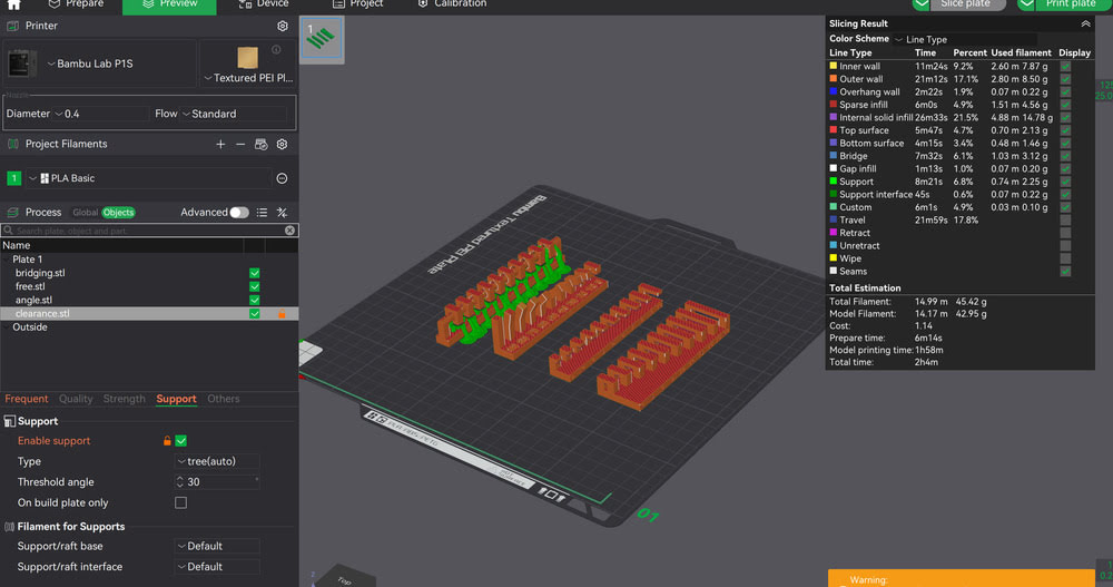
Bridging
Flat Overhangs
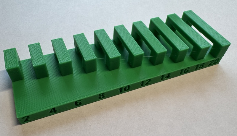
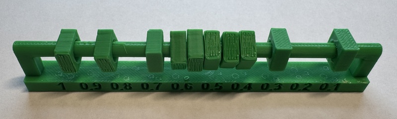
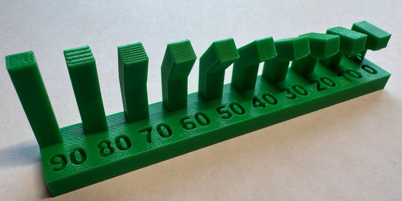
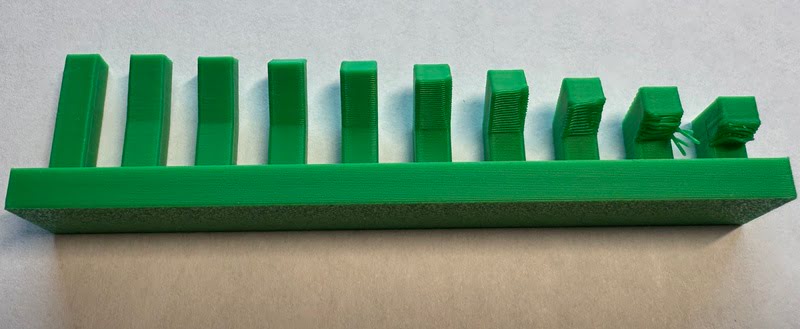
Tolerances
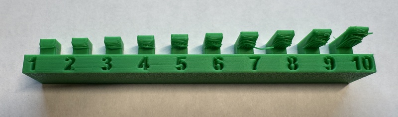
Angled Overhangs
Project Plan
I have a good amount of experience with 3D printing and so I want to try and focus on finding the tolerances of the machine. With that being said,
I want to try and design a print in place planetary gear box. I think this would be super useful in terms of a modular robotic system while also presenting
a good challenge.
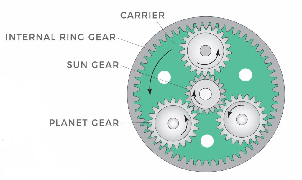
For context, this is a planetary gear box:
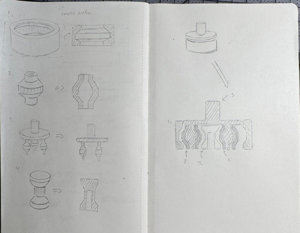
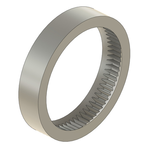
Below is the initial sketch/idea for each component I'll need to design for the system to work. It is separated into the ring, planets, sun gears and planet carrier. The main concept is to use overhangs
as a means to retain the parts inside the frame.
The Design
I have messed around a little bit with generating gears in Fusion using the built in spur gear add in. I wasn't quite sure on how to actually make a planetary gear box though, specifically, I wasn't sure how to find the number of teeth I would need for each gear. After some research, I found this great YouTube video about modeling a planetary gear box by RELUvance. In the video, he showed how to use some simple equations to determine the size of the gears needed for the design. \[N_s = \frac{N_r}{\frac{1}{G_r}-1} \qquad N_p = \frac{N_r - N_s}{2}\] \(N_i\) represents the number of teeth on the planetary, sun, and ring gears respectively. Gr represents the gear ratio that you want. You also choose Nr as a starting point.
Once you have found the number of teeth needed for each gear, you should use the formula below to test if they will all mesh properly together. They will mesh if the result of the formula is a whole number. \[\frac{N_r + N_s}{P}\] \(P\) represents the number of planets you want to use. Arbitrarily, I decided I wanted to use 72 teeth and make a gear ratio of 1:5. Using the equations above, I determined that \( N_p = 27\) and \(N_s = 18\). Before I leapt into Fusion and even though I was planning on using the spur gear add in to generate the gears, I wanted to read a little bit more about the design and specifications of gears and I found this document helpful.
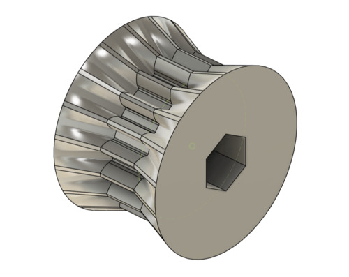
To make the gears themselves, I used the spur gear generator add-in in Fusion.

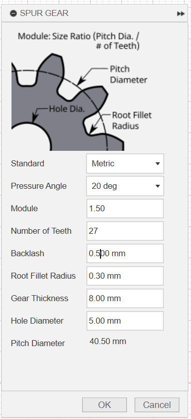

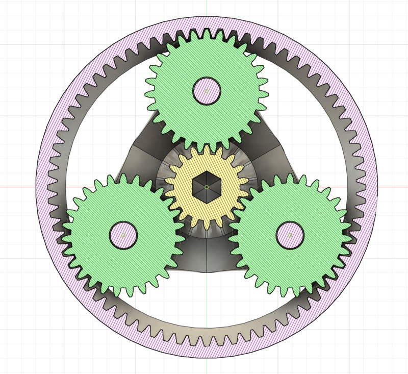
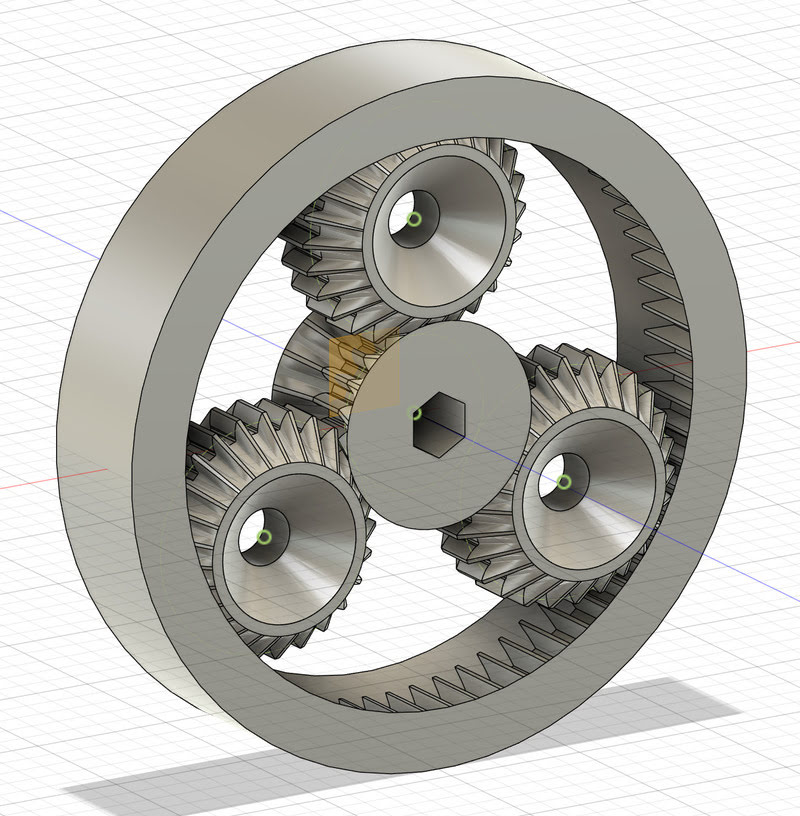
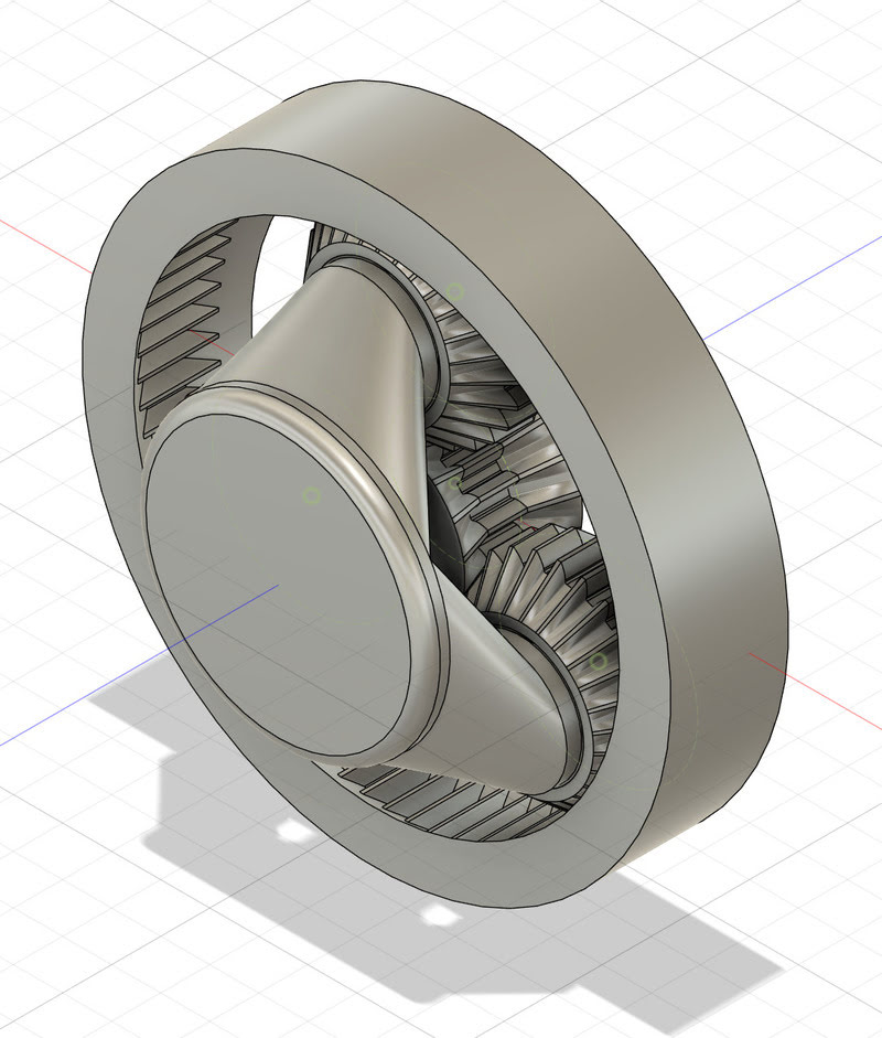
After generating the gears, I moved them into the orientation using the pitch diameter to ensure they were at the correct distance from one another. I forgot to take a picture after this step and so this is a section
view of the final design that shows the layout of the gears.
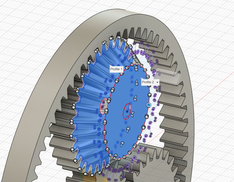
After the gears were in place, I moved on to designing the system that would hold them in place. As I mentioned above, I wanted to use angled overhangs as a means to restrain the parts. To do this, I used a construction plane
offset from the face of the gears and drew multiple circles to serve as the surfaces I would loft to. I learned that Fusion is particular when using the loft function. You either have to loft from a sketch to a sketch or a
face to a face. You cannot loft from a face to a sketch, it will raise an error and not perform the operation.
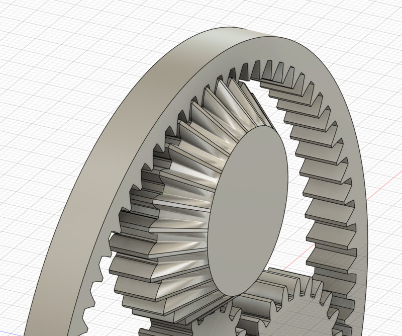

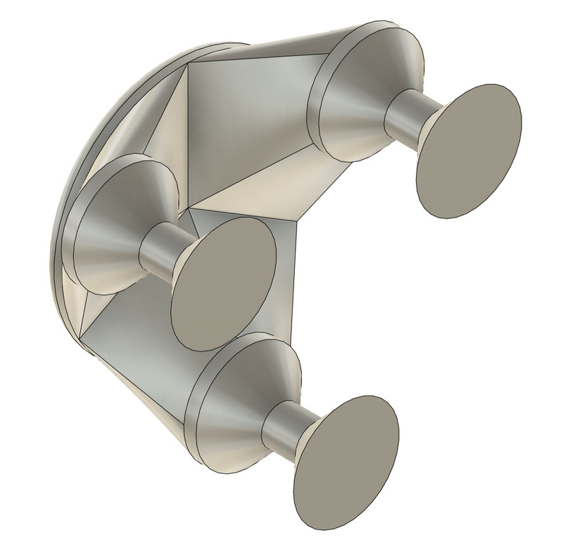
With that, the final step was to add the carrier and design it to fit in the holes in the planets while still being free to rotate. I decided to use another offset plane and loft the pins
that I had designed to a circle sketch on the new offset plane. Importantly, I adjusted the offset distance until the angles created by the loft would be able to print without supports,
adjusting the distance of the offset plane from the gears until.
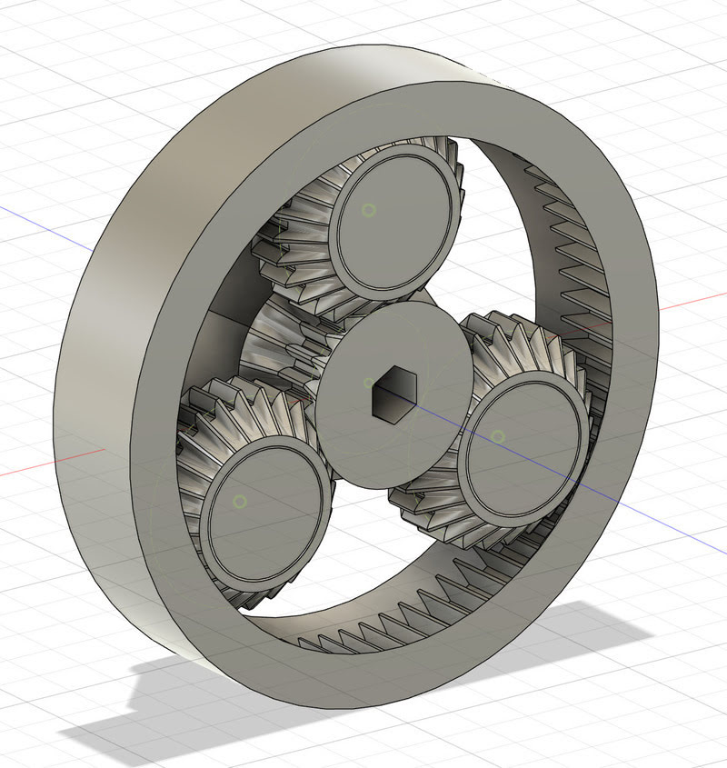
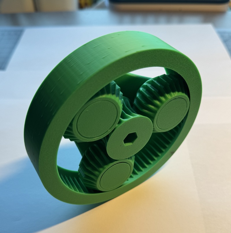
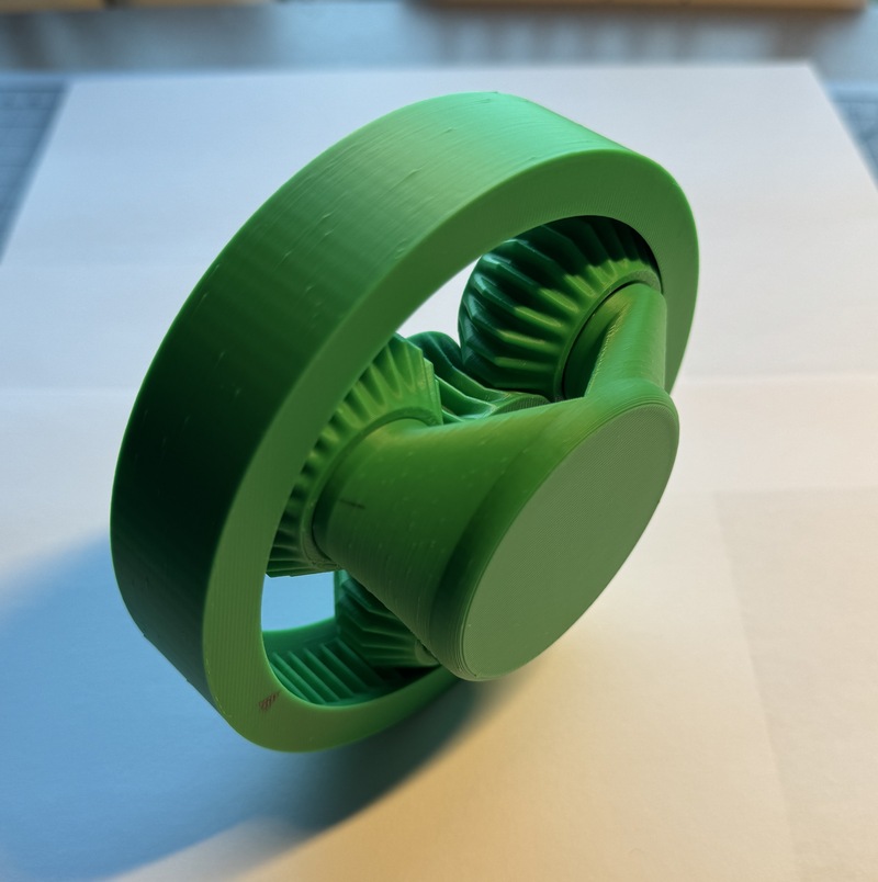
The Final Model
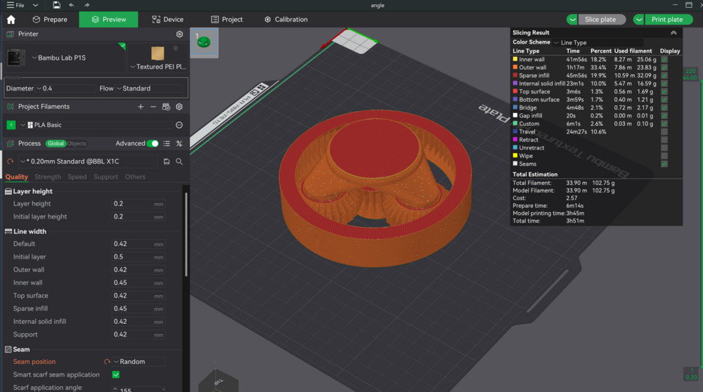
3D Printing
With the design completed, it was time to move on to printing! While in the slicer, I kept most of the initial settings the same, however, I made the seam position random. The seam position
determines where the printer starts each layer. While it is nice to have it all start in the same place on each layer for a nice, consistent look, I figured that it would potentially come
through in the final motion of the gears as a bump every time and wanted to remove it.

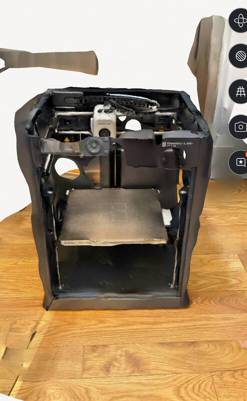
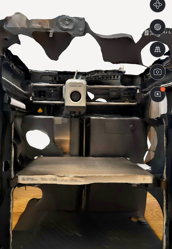
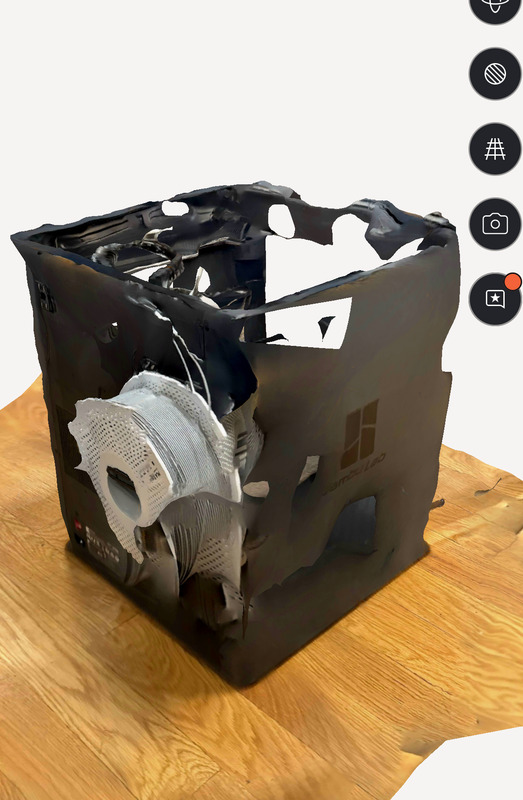
3D Scanning
I thought it was fitting to try and scan my 3D printer and see how it could handle a complex object. I tried using an app called Polycam with its photogrammetry option. It was super simple to get started,
all I had to do was press "start scan" and then move my phone around the printer and it began automatically taking a bunch of photos. It then uploaded them all and then spent a few minutes doing all the
computation and returned the scan. I was able to navigate through the scan on my phone, using two fingers to move around, zoom in, or pan.
Thoughts and Reflection
I think this week went pretty well! I was super excited to be able to use my own printer and do all of the characterization prints on it to get a better understanding of the machine's capabilities.
I might do a few more in the future and add them to this page where I test clearance but done in the xy plane and maybe longer bridging as it didn't seem to have a problem.
As for the design, I am super happy with how the gear box turned out. In particular, I think it's great that I was able to stick almost entirely to the design outlined in the original sketch. I mentioned
it above, but, I think I was a little too cautious with my tolerances and could have made them slightly tighter achieving a better final fit. That being said, everything moves very freely with no resistance
which is also important to a gear box. It would simply take further exploration to determine what the best fit would be.
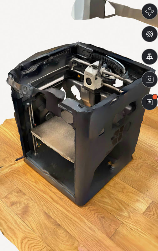
In regards to the scanning, I was surprised by the ease of use of the program that I used, Polycam, but was less impressed with the accuracy of the scan itself. I think a lot of it was in fact user error
and with more practice I could get better scans. I also think it would be better for smaller objects where all the photos you take can be more localized as opposed to spreading them out across such a
large space with so much detail.