Week 4: Electronics Design
Research
I have little to no experience in this department and so I think a lot of my time this week will be spent becoming familiar with the uses of the componenets themselves, the communication systems, and how they all fit together. I'm going to use ChatGPT 5 as a means to gain some baseline understanding (the converstaions will be linked at the bottom of the page). To get a more indepth understanding if needed, I will then likely continue to more detailed and specialized resources.
Communication Systems
After talking to ChatGPT and based on what was mentioned on the class website I learned that there are four main communication systems that might be used: I2C (Inter-Integrated Circuit), SPI (Serial Peripheral Interface), ADC (Analog-to-Digital Converter), and UART (Universal Asynchronous Receiver/Transmitter). Below is a summary of the information I learned in my converstaion with ChatGPT
I2C (Inter-Integrated Circuit)
Communication is send through a 2-wire bus using the SDA (serial data) and SCL (Serial Clock) pins on the microcontrollers.
It works in a main/secondary relationship; the master typically being the microcontroller and the secondaries are the sensors/displays.
The data is sent in packets controlled by the clock pulses.
Pros
- Super efficient pin wise, only needing two
- Supports multiple devices very easily
- Widely accepted for sensors
- Not very fast
- Bus is shared and so you can run into jams when using too many devices
- Good for short distances ~ 1 m, doesn't work much longer thatn that
SPI (Serial Peripheral Interface)
Communication is sent through MOSI (Main out Secondary In), MISO (Main In Secondary Out),
SCLK (Clock), CS/SS (Chip Select/Secondary Select - one per device). The master provides the clock and contorls
which secondary is active. The data is also shfited in and out on each clock pulse.
Pros
- Much faster thatn I2C
- Can communicate with multiple secondary simultaneously
- Requires at least 4 pins +1 for each additional device
- Not great for long distances
ADC (Analog-to-Digital Converter)
Converts a continuous analog voltage into a digital number. The resolution depends on how many steps
the ADC divides the voltage into.
Pros
- Lets digital systems process real world data
- Built into most microcontrollers
- Works seamlessly with sensors
- Resolution and speed are finite, loss of precision
- Can be noisy
UART (Universal Asynchronous Reciever/Transmitter)
Communication is sent in serial, each bit of information is sent one at a time along
a single wire. Uses the TX (transmit) and RX (recieve) pins on microcontrollers to
communicate. They do not share a clock line and so they must set a baud rate (bits per second).
Pros
- It only uses two wires and so it is quite simple
- Better for long distances ~15 m while using lower baud rates
- Widely supports
- Only enables communication from one device to another
- Limited number of UART communication pins on microcontrollers
Getting Situated
I started using by using the Falstad AVR8JS simulator, allowing me to use code as well as see the analog side of the circuit. I quickly left it behind as it is mostly an analog simulator as opposed to a digital simulator which I would need for any of the projects that I wanted to work on. I ended up using Wokwi for the week.
Project Plan 1...
This week I want to try and design a device for sailing. I am on MIT's varsity sailing team and I practice Tuesday through Friday every week. I think it would be super valuable if during practice I was able to see my current speed and heel (angle of the boat to the horizon) on a screen that mounts to the mast of my boat.
To get started, I turned to ChatGPT to determine what components I would need. I thought that I would want an esp32c3 to enable
multiple devices to report back to one main device potentially on a coaches boat so they can see the differences in the speed of
the boats. I then was debating whether or not I wanted to include a solar panel so that the device could recharge while its on
the water but I determined that it would be better to keep the first design simpler and so I want it to just be battery powered...
After further thought, I am going to abandon this idea as I have something that I think will be more useful/applicable. I want to make
a breakout board that is purpose built for testing servo motors and stepper motors with room for input devices and output devices.
Project Plan 2
As I said above, I want to design a development board focued on the use of stepper motors and or servo motors. I want to also make it easy to add additional input devices to control the motors such as limit switches. I want to be able to support at least three stepper motors and at least three servo motors. I want it to have a few built in potentiometers or buttons to control the motors. I am now planning on using the Pico W as I will need many more pinouts than are available on the XIAO RP2040.
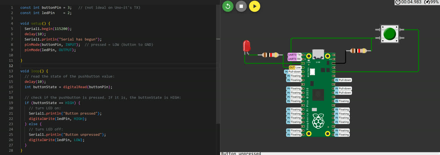
Execution
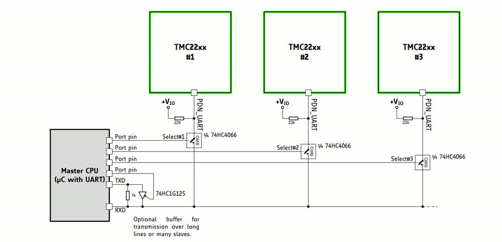
I spent a good amount of time reading through the TMC2226 Data Sheet and thought I had a rough understanding for how it should be wired within the PCB. I was unsure as to how to control the microstepping pins or if I needed to use the STEP and DIR pins if I was using the UART connector, I planned to meet with Anthony to seek guidance and advice. In the meantime, I spent some time trying to figure out Wokwi to little avail. I've found that Wokwi's servers can get somewhat busy and your compilations may time out and the simulation won't run. I couln't even get a simple button and led to work.
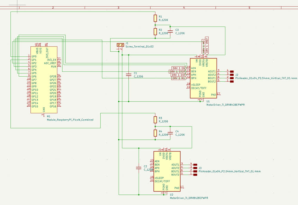
In preparation for my meeting with Anthony, I tried to draw the schematic for what I believed the connections needed to be. Note that this image was taken slightly later
and so there is an additional component that I will talk about later, the focus here is on the TMC2226 and the rats nest of cables.
First, a huge thank you to Anthony for taking the time to sit down and help me figure all of this out, I wouldn't have been able to get anything done
if it wasn't for him.
The first problem that we tackled was dealing with the TMC2226 component and how to communicate with it. The solution was to simply switch the component.
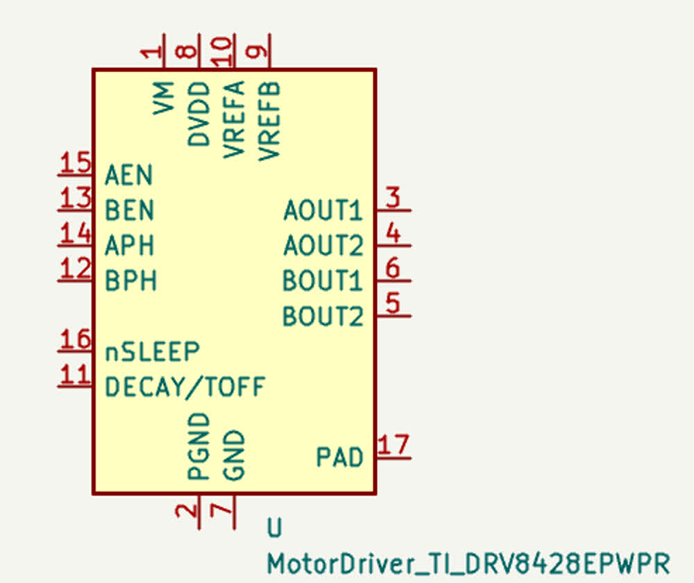
The TMC2226 was far more powerful than what I needed for this situation and would have been overkill, not to mention it has almost 30 pins. Instead, he recommended
using the DRV8428, a smaller and simpler stepper driver that would be easier to work with.
Simultaneously, we dealt with the mess of wires that I had in my schematic, making it difficult to read and understand. Soltuion: simply use labels... I know this was
mentioned in the EDA video but I forgot about them. They made the schematic SIGNIFICANTLY easier to parse and work with.
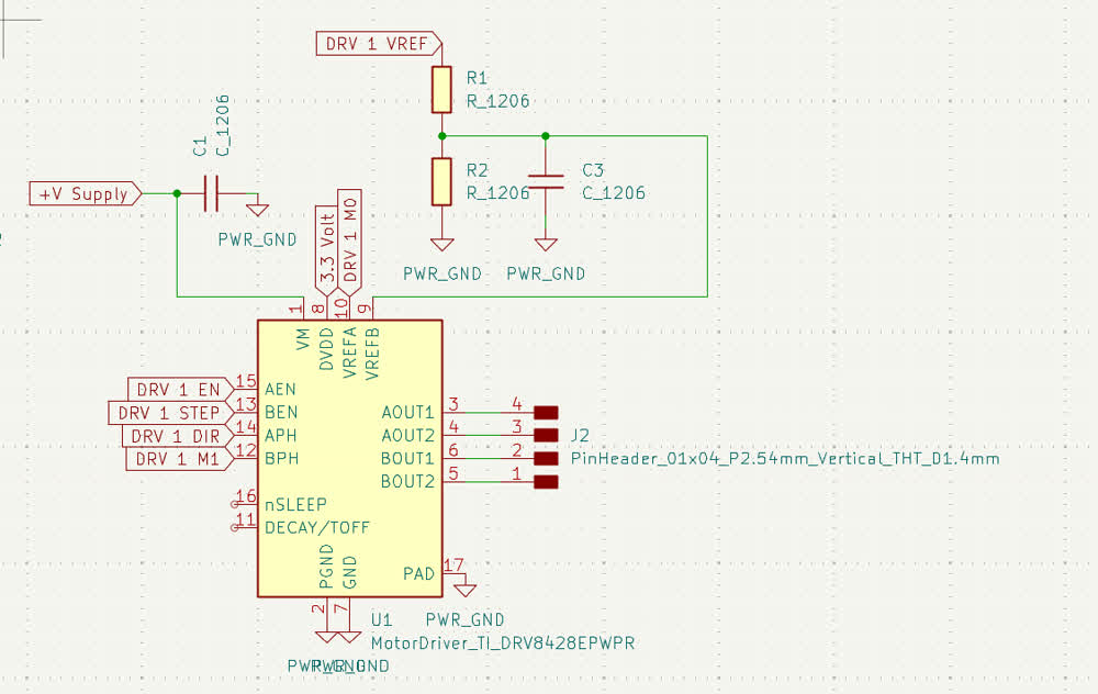
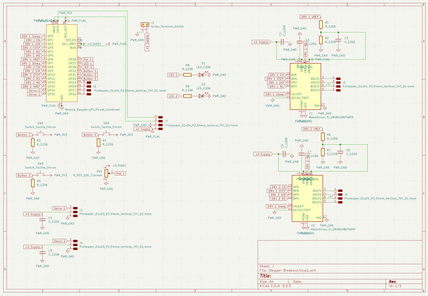
Taking what I learned from my converstaion with Anthony, I went ahead and finished the schematic for the rest of the cicuit! I added 3 push buttons, a potentiometer,
two LEDs, two pinouts for servo motors, and another stepper drvier. That sounds like a lot, but after having wrestled with the stepper driver alone for probably and hour
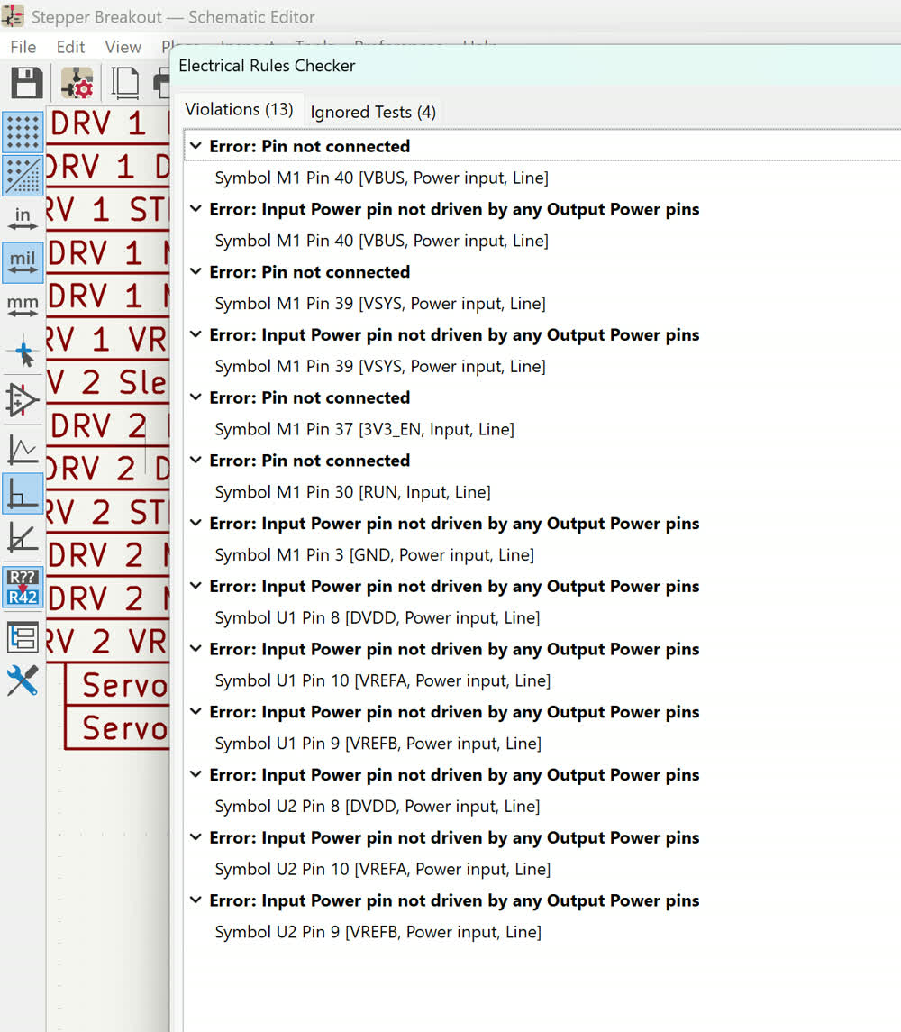
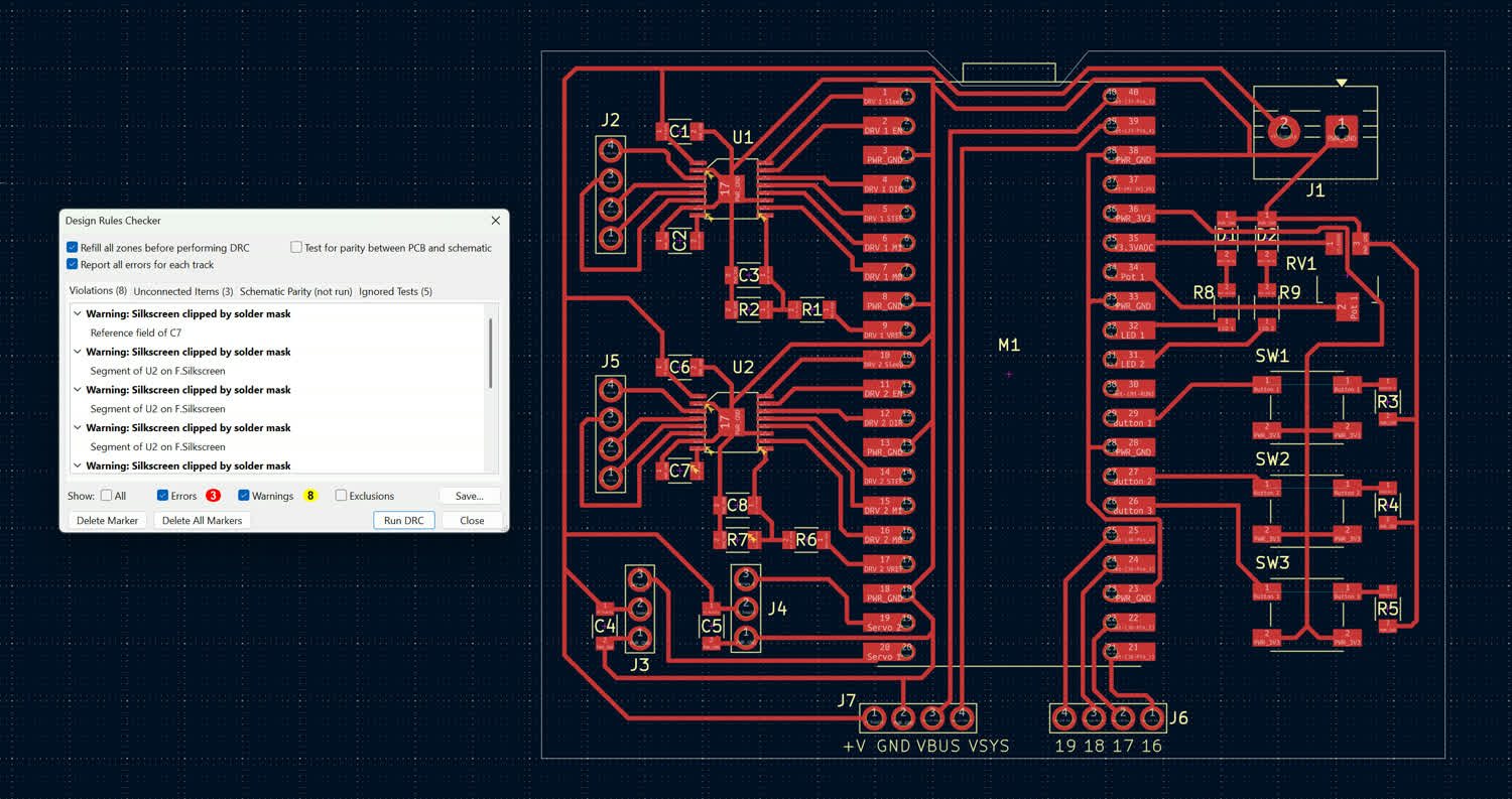
and a half, the rest of the components felt trivial. I then went on to use the electrical rules checker (ERC) and resolve any errors that it threw at me (there were many).
Almost. if not all, of these errors were solved by using power flags to signal whether or not something was a power source as Kicad believed that nothing was actually
getting power.
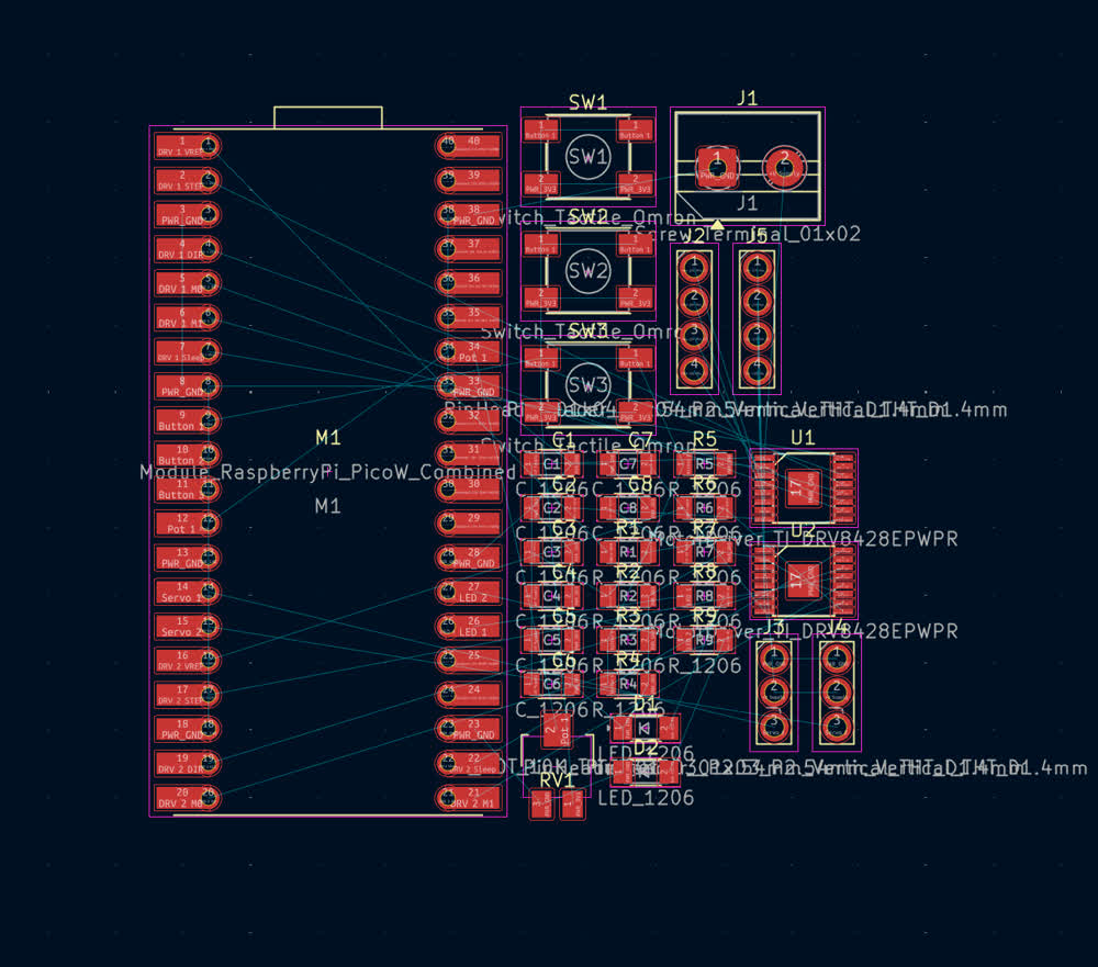
Once the schematic was finished, I had to open up everything into the PCB editor. When I did that, what I initially got looked like this:
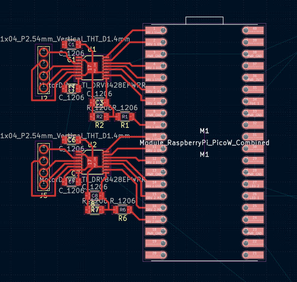
The first problem that I encountered was that while using the settings recommended in the EDA video, .4 mm clearance and the .4 mm min. track width, I was unable to actually
connect to the DRV8428 drivers, they were too small. In order to move forward, I abandoned the constraints and figured I could tackle them later, getting a recommendation from
the staff. This enabled me to wire both drivers to the Pico W. Again, having the schematic open and relabeling pins made this SIGNIFICANTLY easier.
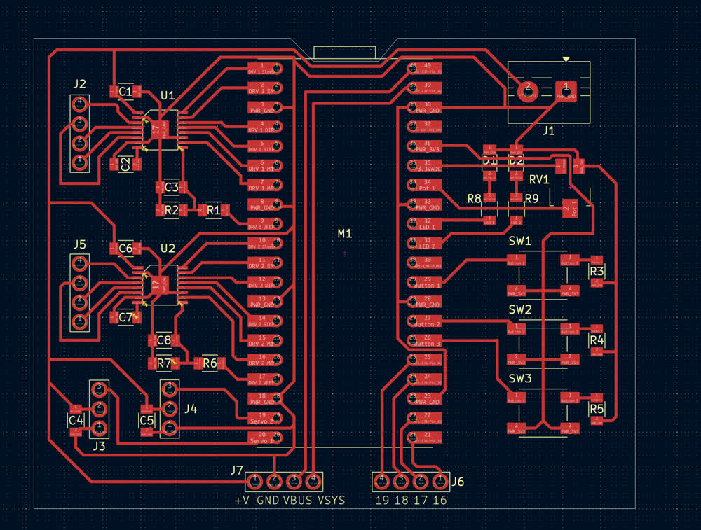
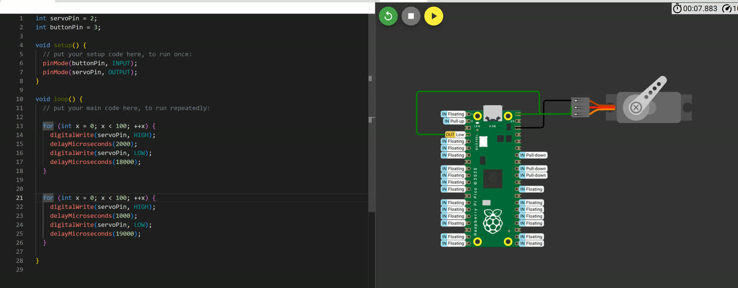
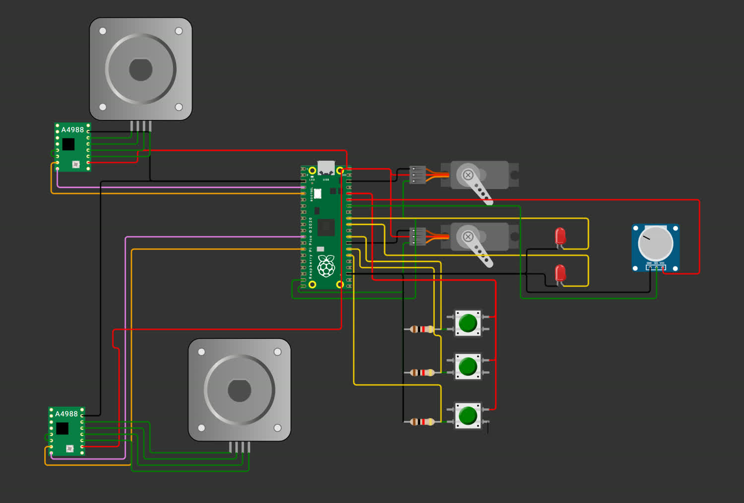
After completing the PCB, I went back to Wokwi to model the entire circuit as seen below:
Thoughts and Reflection
All in all, I am pretty happy with how this week turned out. I was stuck for a long time, trying to figure out what exactly I wanted to build and what might be useful towards my final project. The sailing device, while cool, I think would have been a little complicated and would have strayed from any project I had in mind completely. I am actually super excited about the stepper/servo focused development board, I've spent a good amount of time working with steppers and servos in the past and to have everything already set up without tons of wires all over the place would be huge! I also think it is totally on track with the rest of my project, designing some form of modular robotic system.
Time management was still a big problem this week, even though I thought I started early. Just because I started work for the class on Saturday doesn't mean that I am making progress towards the deliverable right away. I think next week I want to start the deliverable itself earlier, and I can do the research as I go. It is not beneficial to cram the design of a schematic and PCB into a day and a half long stretch.
I was disappointed that I wasn't able to use AVR8JS to simulate my project, I was looking forward to it. I messed around with Falstad a little bit in highschool and was super excited to see how my digital circuits would work with it but it turned out they were a little to digitial for the analog simulator. It didn't have some of the components that I would need to actually model the system, I would like to return to it at somepoint. I was getting pretty frustrated with Wokwi in the end, whether it was because it kept timing out, raising errors, or simply not running, the whole process was unenjoyable.
Actually designing the schematic and the PCB was difficult but also enjoyable. It has been something that I've wanted to learn for a while and so it was great to finally dig in and work through a problem. It was also great as it forced me to read through data sheets carefully to make sure that I was actually wiring everything up correctly. I'm quite proud of how it turned out in the end.
Data Sheets