Week 6: Computer-Controlled Machining
Project Plan
I was sitting in my room and couldn't seem to find a project for the week that could be used in relation to my final project. My thoughts started to wander and I was looking around my room. I saw my feet resting on our coffee table and then considered the coffee table itself. I soon convinced myself that I could design and make a better one. The project for the week: a new coffee table for my bedroom.
The Training
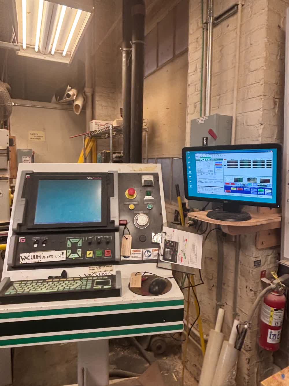
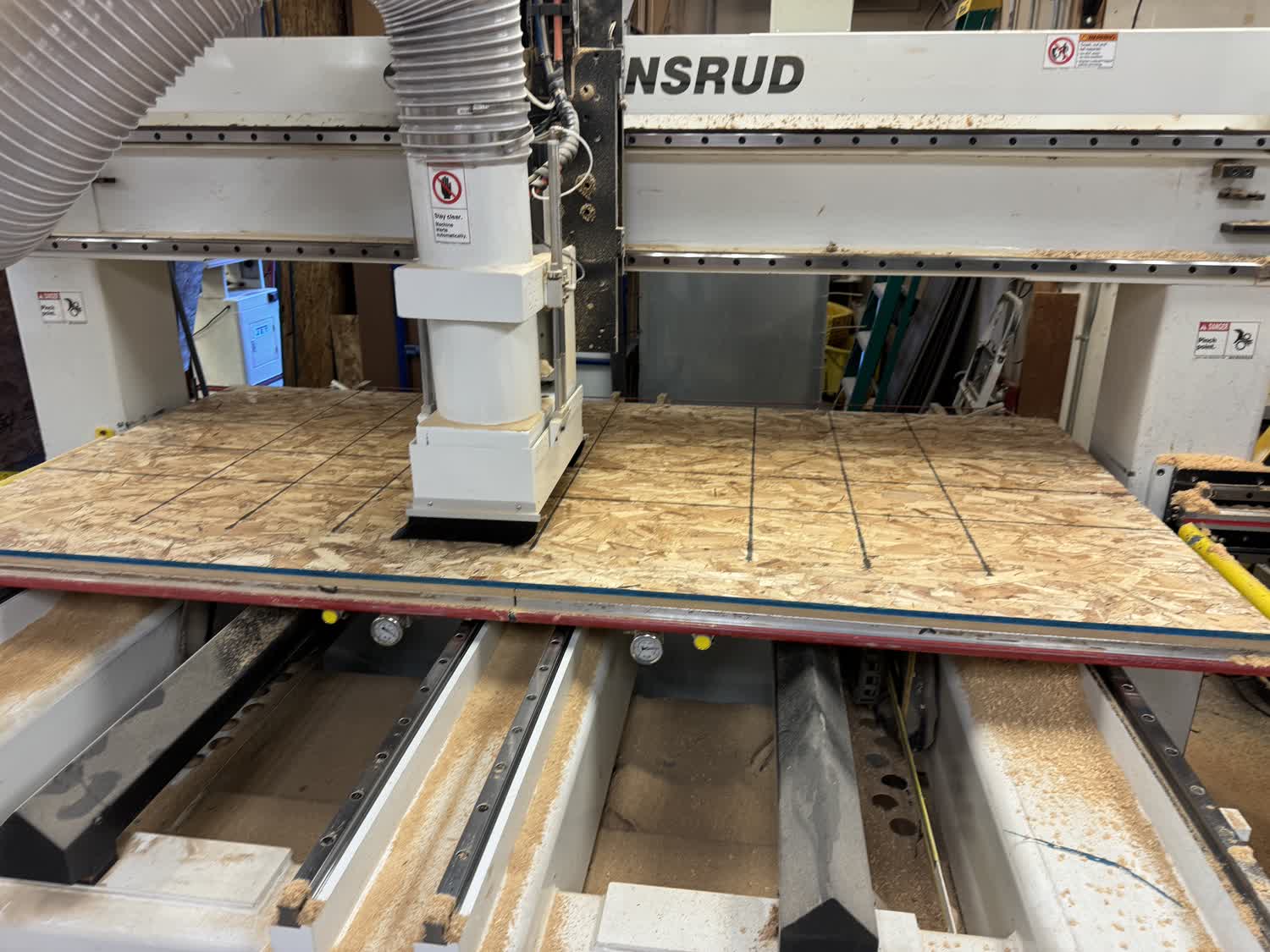
I went to the training for the Onsrud 3-axis router in the Architecture department's wood shop in building N51, hosted by Chris Dewart. During the training,
we discussed shop policies and safety procedures. We then began working with Mastercam and the Onsrud. Chris didn't elaborate much on how to work within Mastercam.
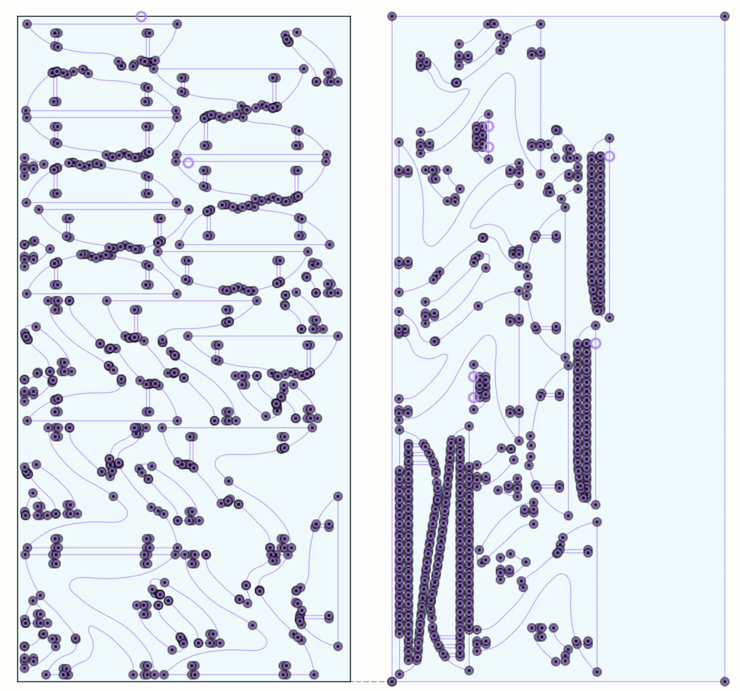
He told us that once we sent him the DXF files of our designs, he would handle the CAM setup and then we could cut out our parts. During the training, we cut out the
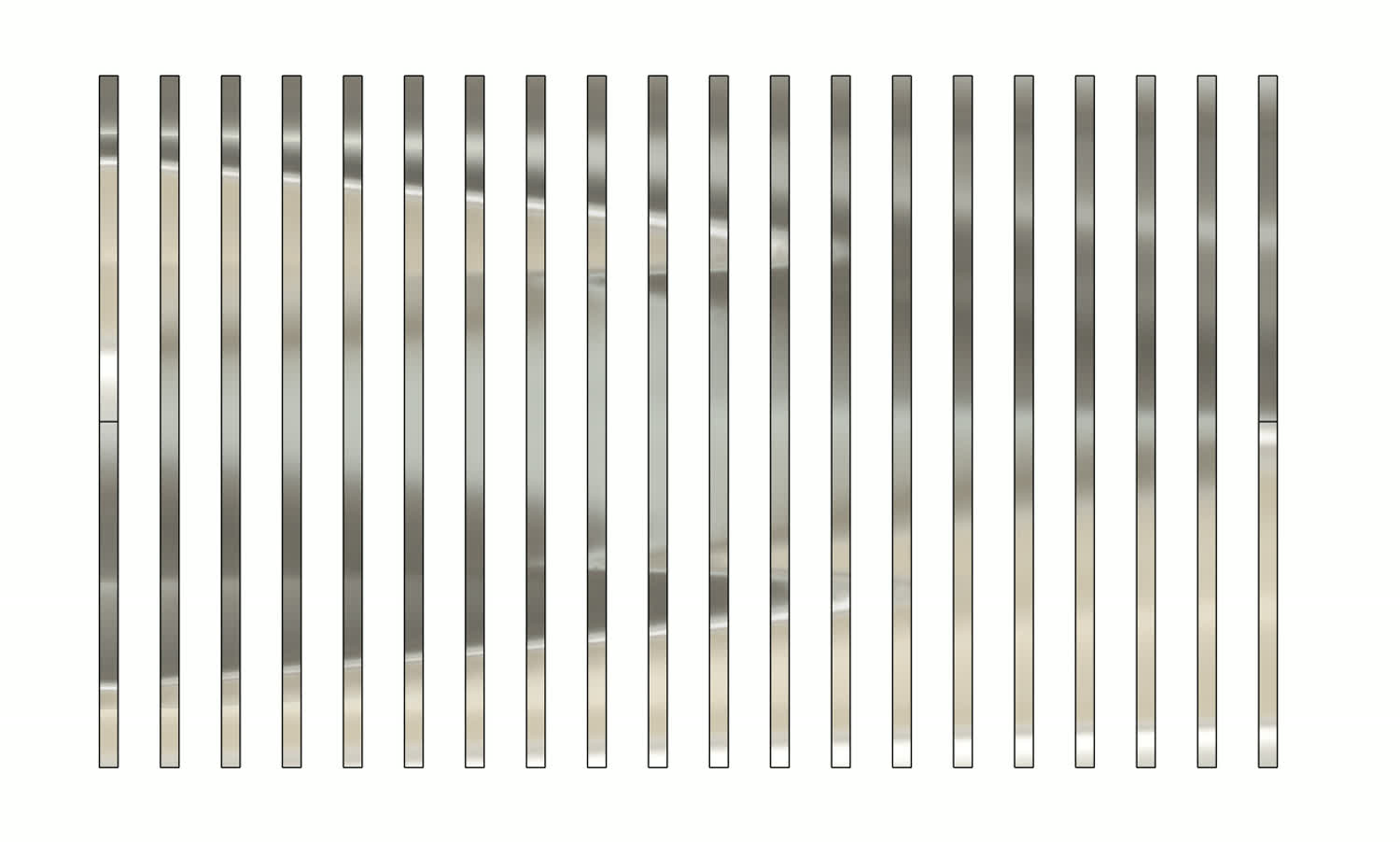
test parts to see the fit of the plywood that we would be using for our project. The Onsrud has a built-in tool changer, and so Chris added the tool changes to the CAM
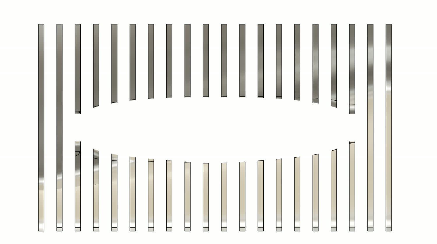
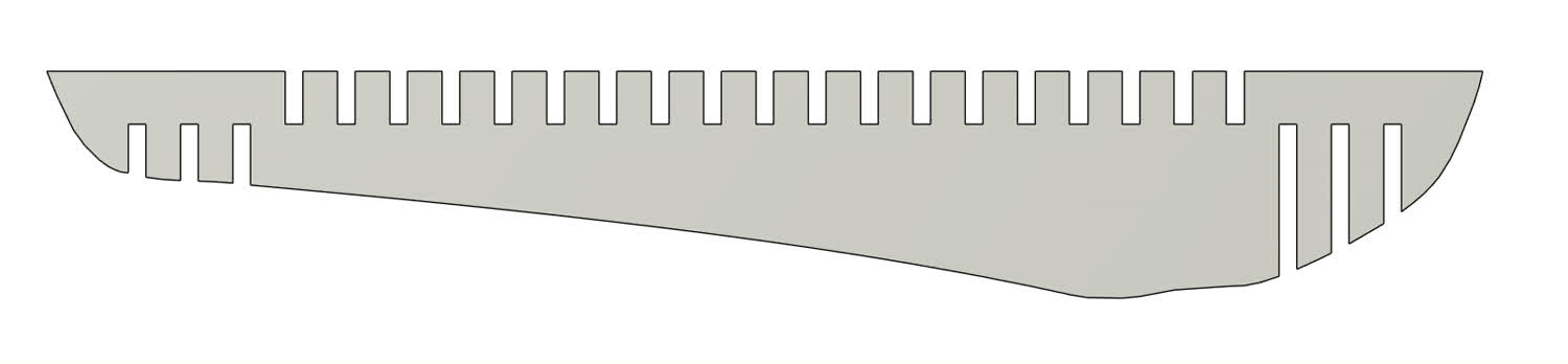
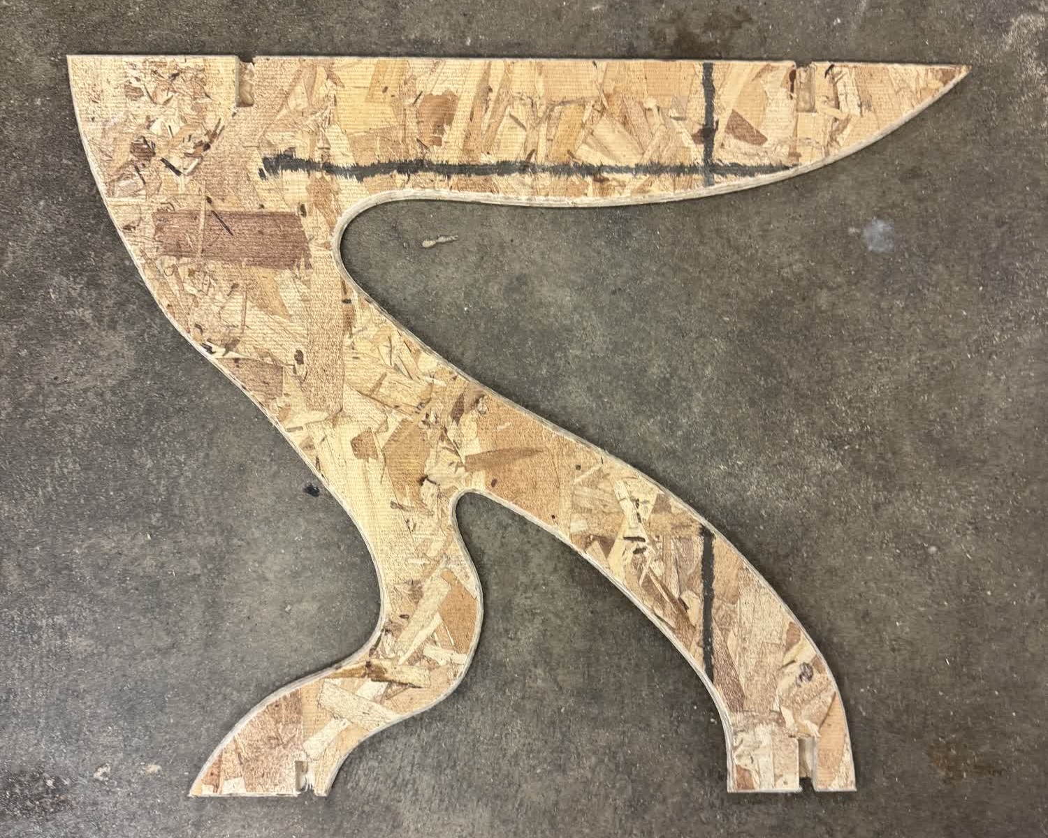
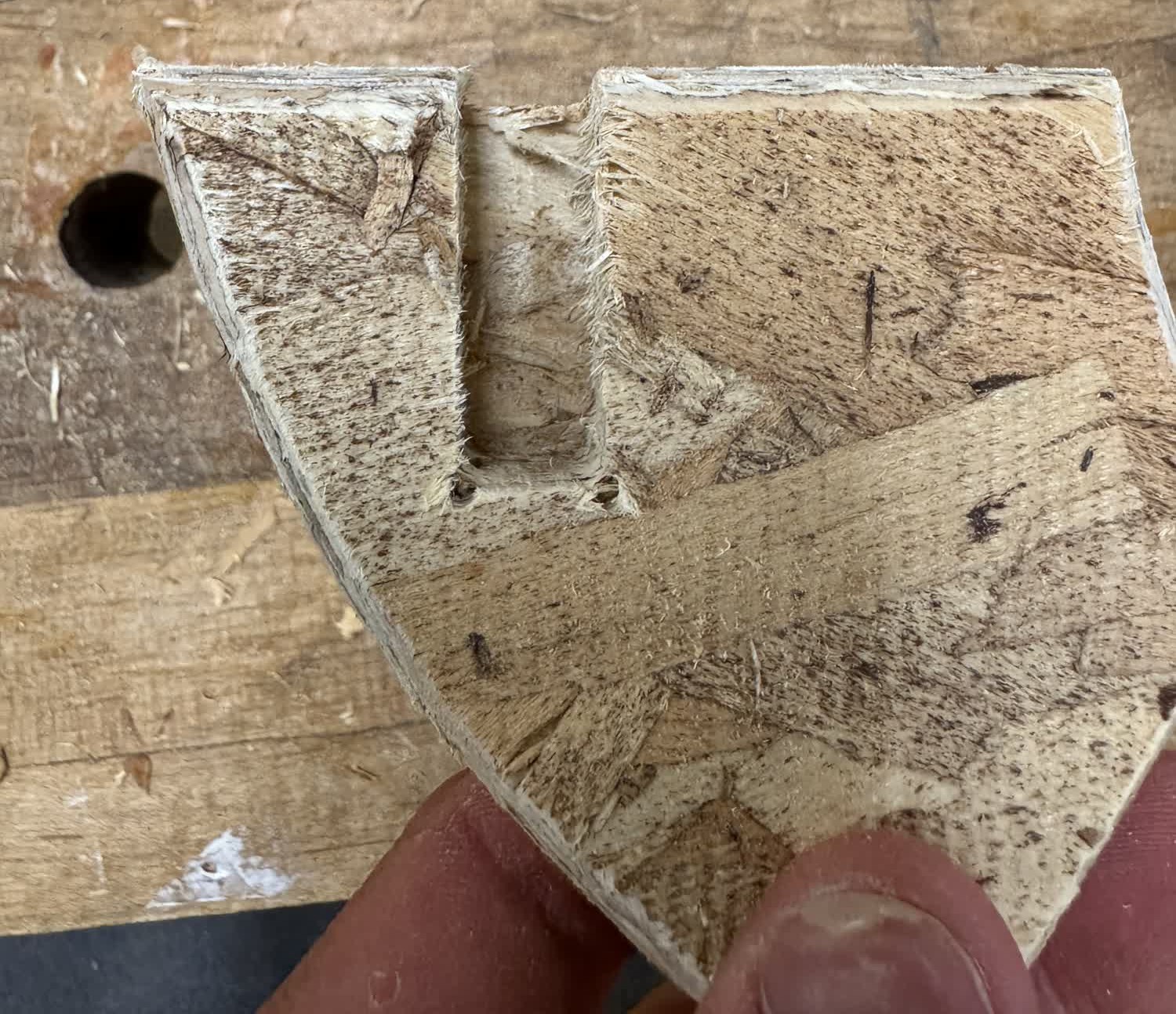
program before he sent them to the machine. The standard order would be to drill out the corners of any dogbones with a 1/8-inch drill bit. Then, use a 1/4-inch downcut end mill
to cut out all of the bodies, leaving an onion skin to hold the parts in place. Finally, we'd use a 1/8-inch downcut end mill to clean up the fillets left
by the larger end mill in the corners of the dogbones, where the relief holes were drilled.
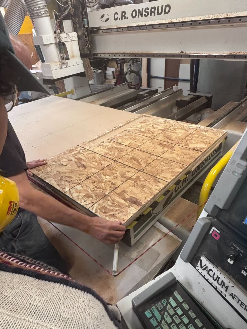
During the training, Chris talked about the importance of constantly measuring the stock, as it can change based on the weather. I.e., if it rains, the stock will absorb
water and be wider than it otherwise would be. When we tested fits with the components we had just cut, we determined that the best fit was the 0.42" gap. We measured
the stock to be 0.433".
Exploration
I wasn't quite sure what I wanted the new coffee table to look like. In the past, I have been interested in tensegrity tables, even making a very simple one out of
popsicle sticks in high school, and so I figured I'd start there. I looked online at a bunch of different examples, and they were certainly interesting. I found an
interesting model of a 3D-printable dual tensegrity table
online that caught my attention. I printed it and then assembled it.
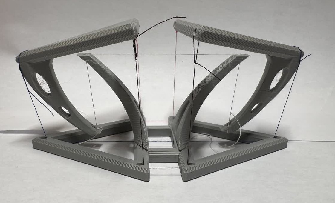
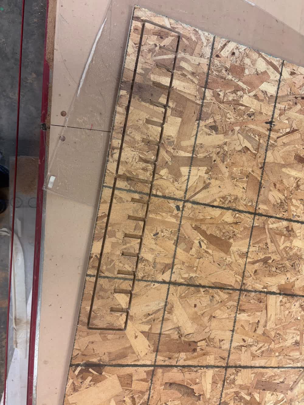
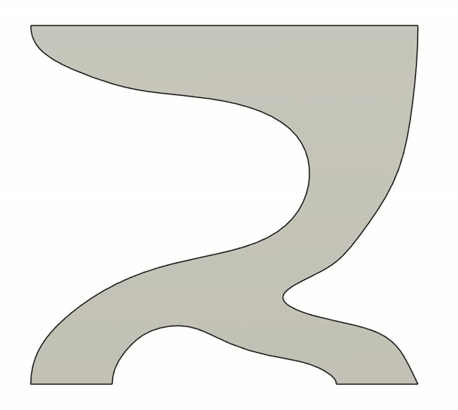
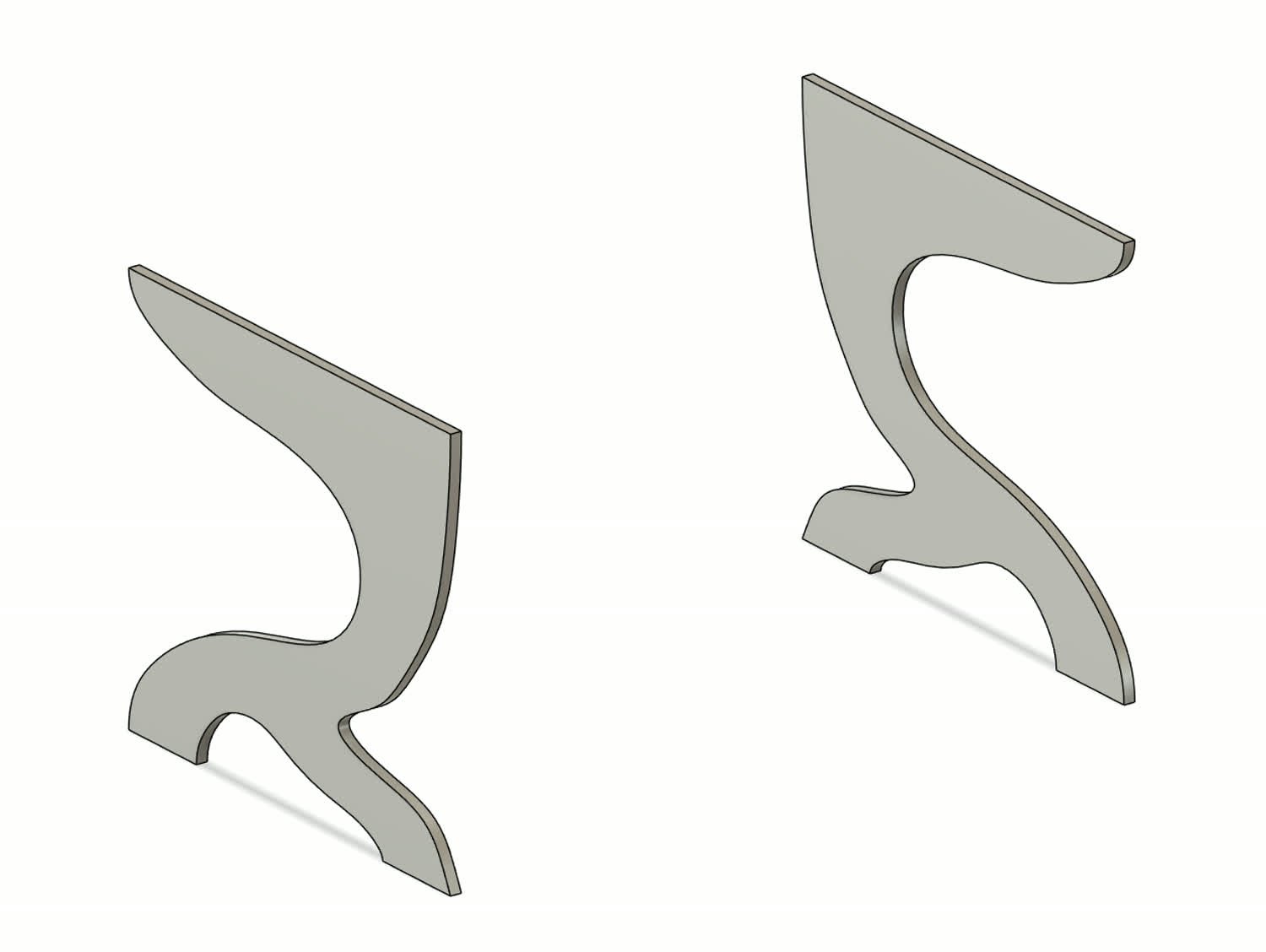
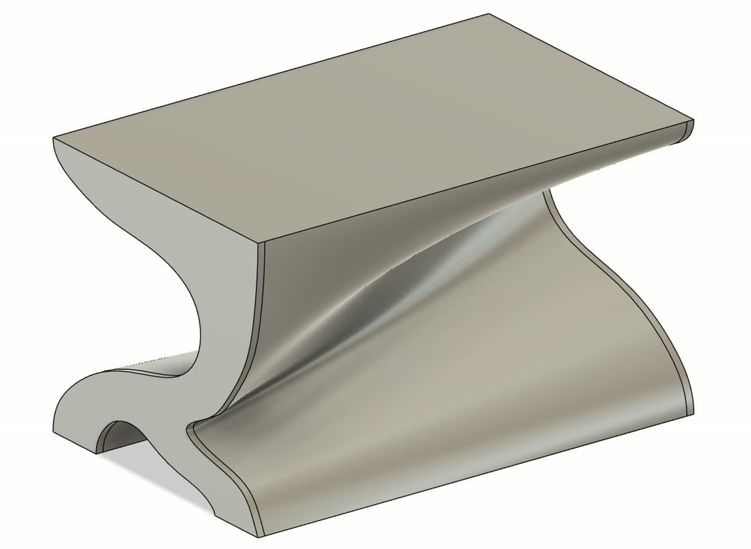
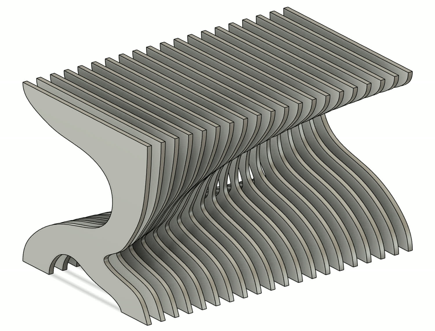
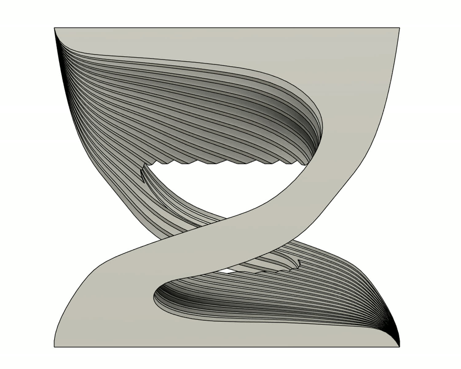
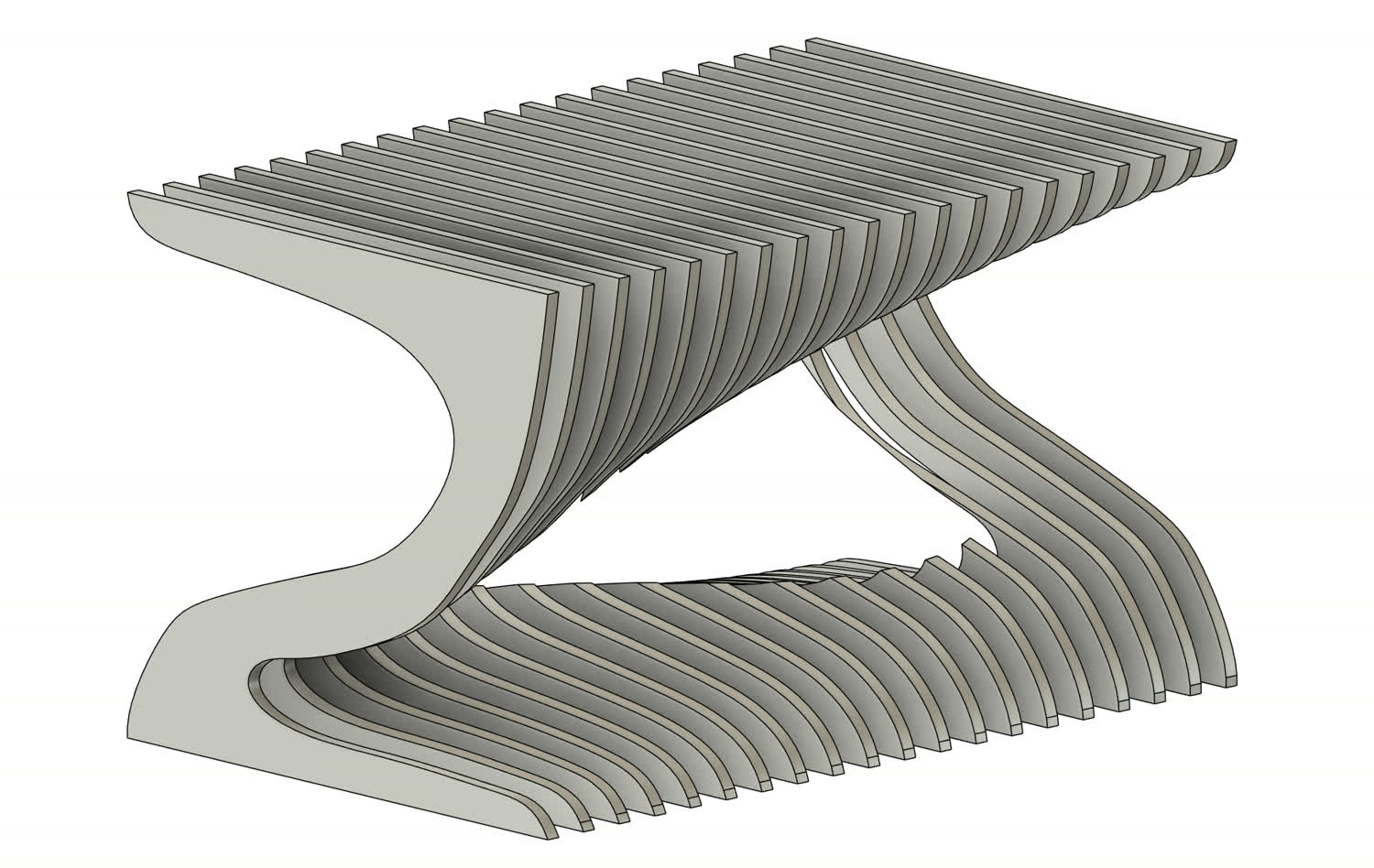
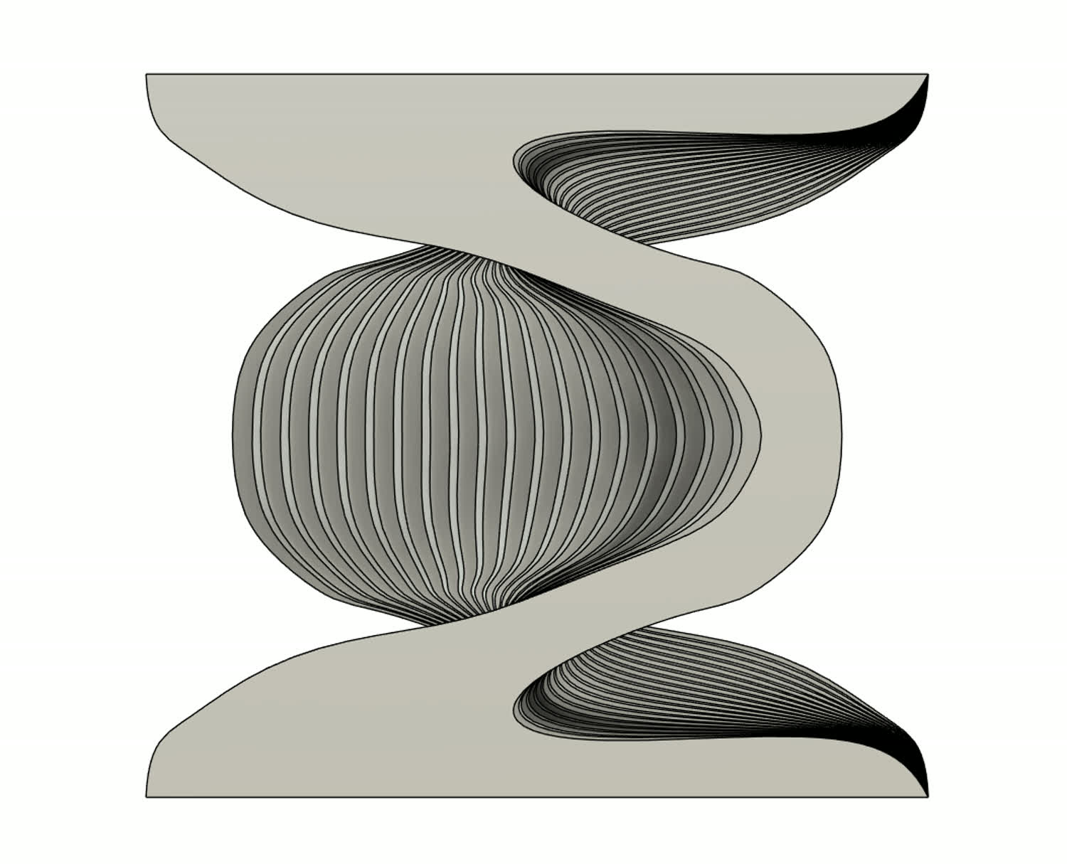
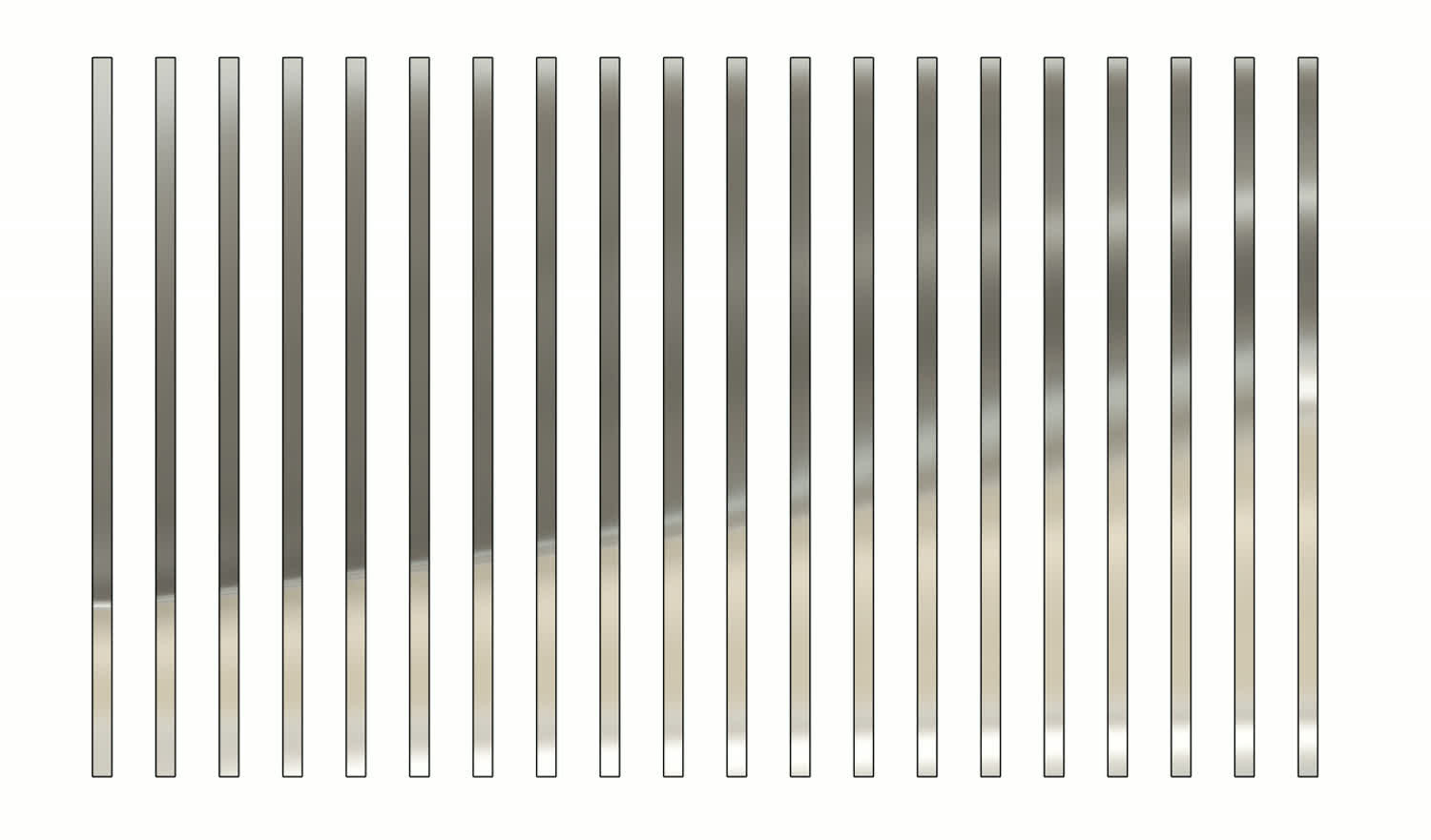
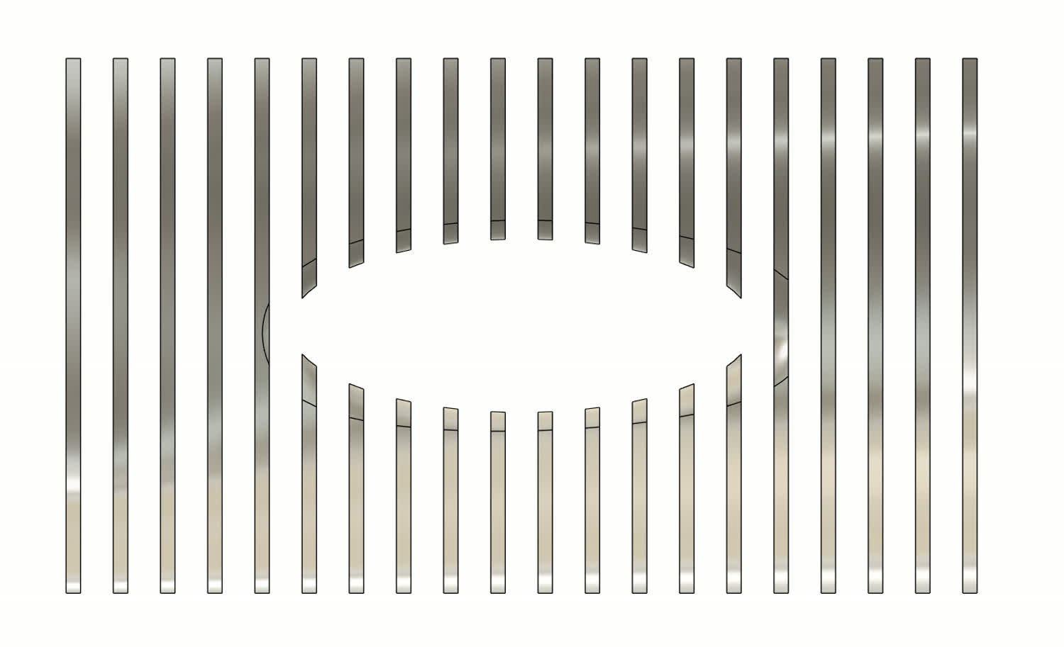
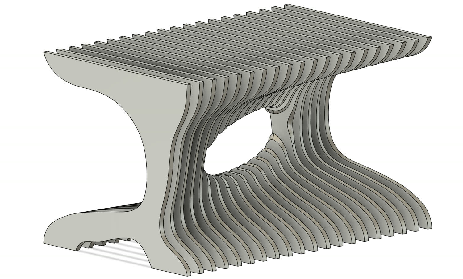
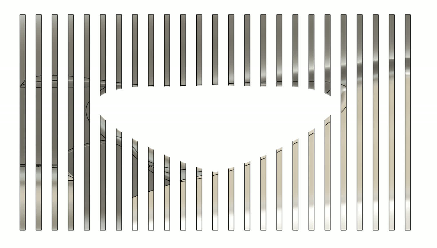
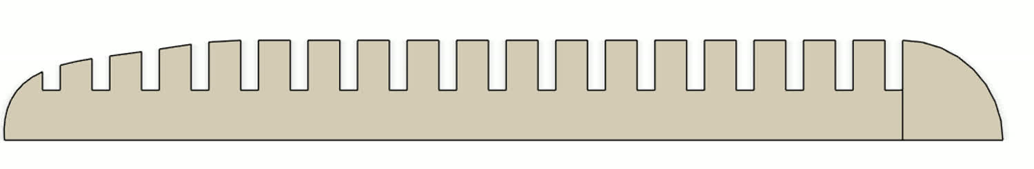
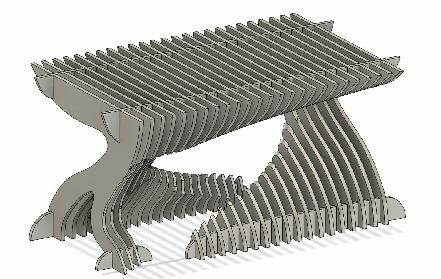
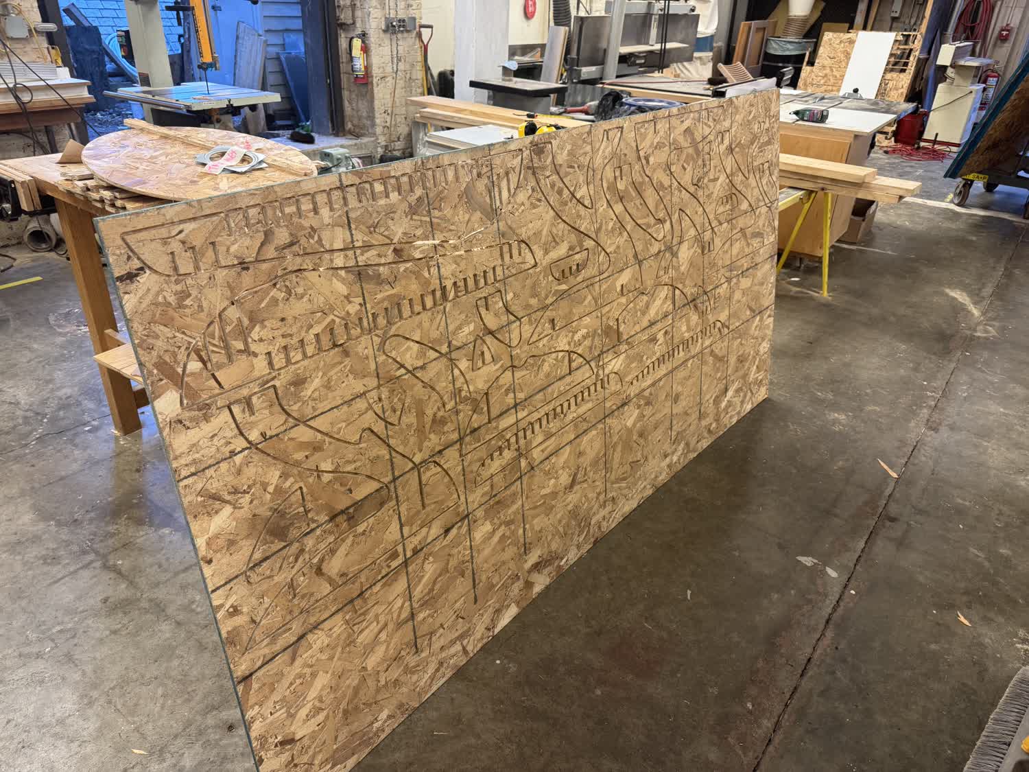
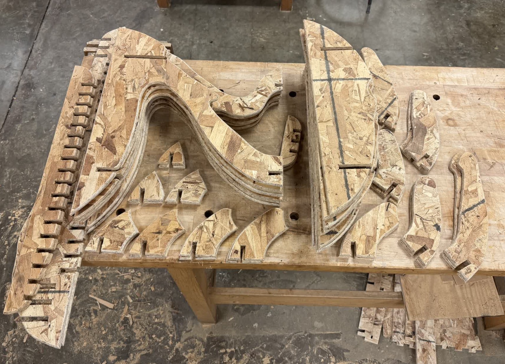
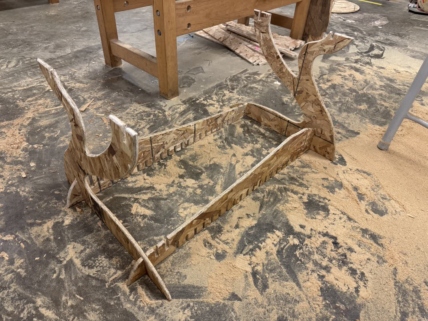
At some point, I remembered seeing what I now know are called contour slats. This idea quickly
caught my attention, and I began modeling different ideas using Fusion 360. Below, I will walk through the general process that I used for each of the designs and then show
a bunch of concepts that I developed in the process.
The General Process
Different Designs
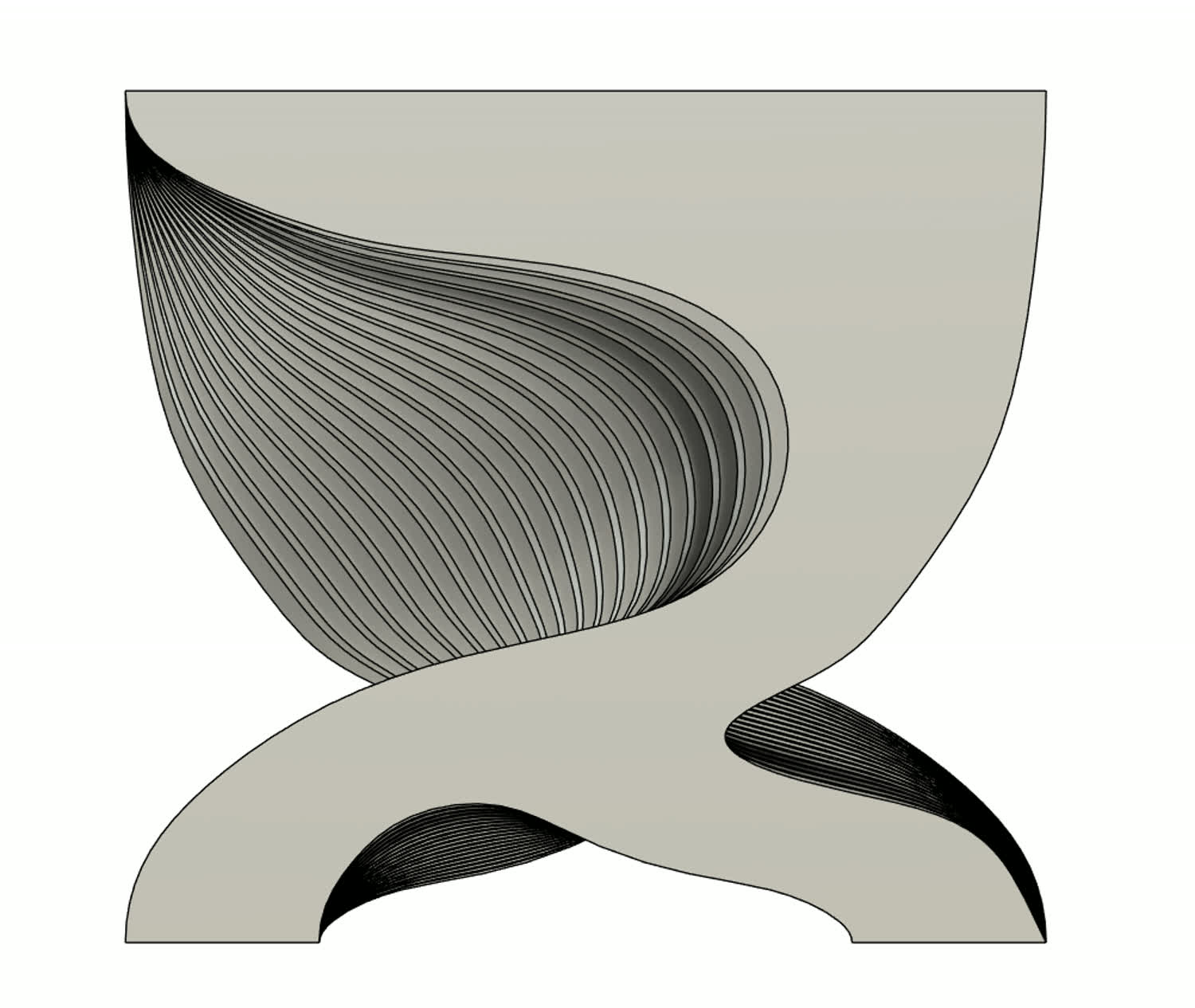
Design 1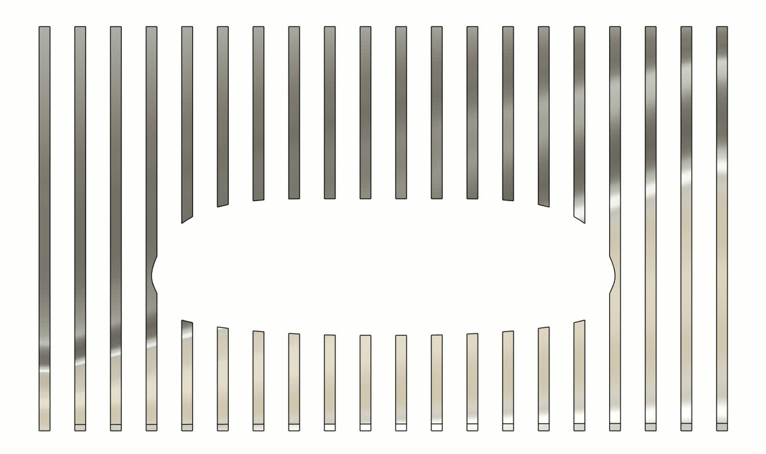

Execution
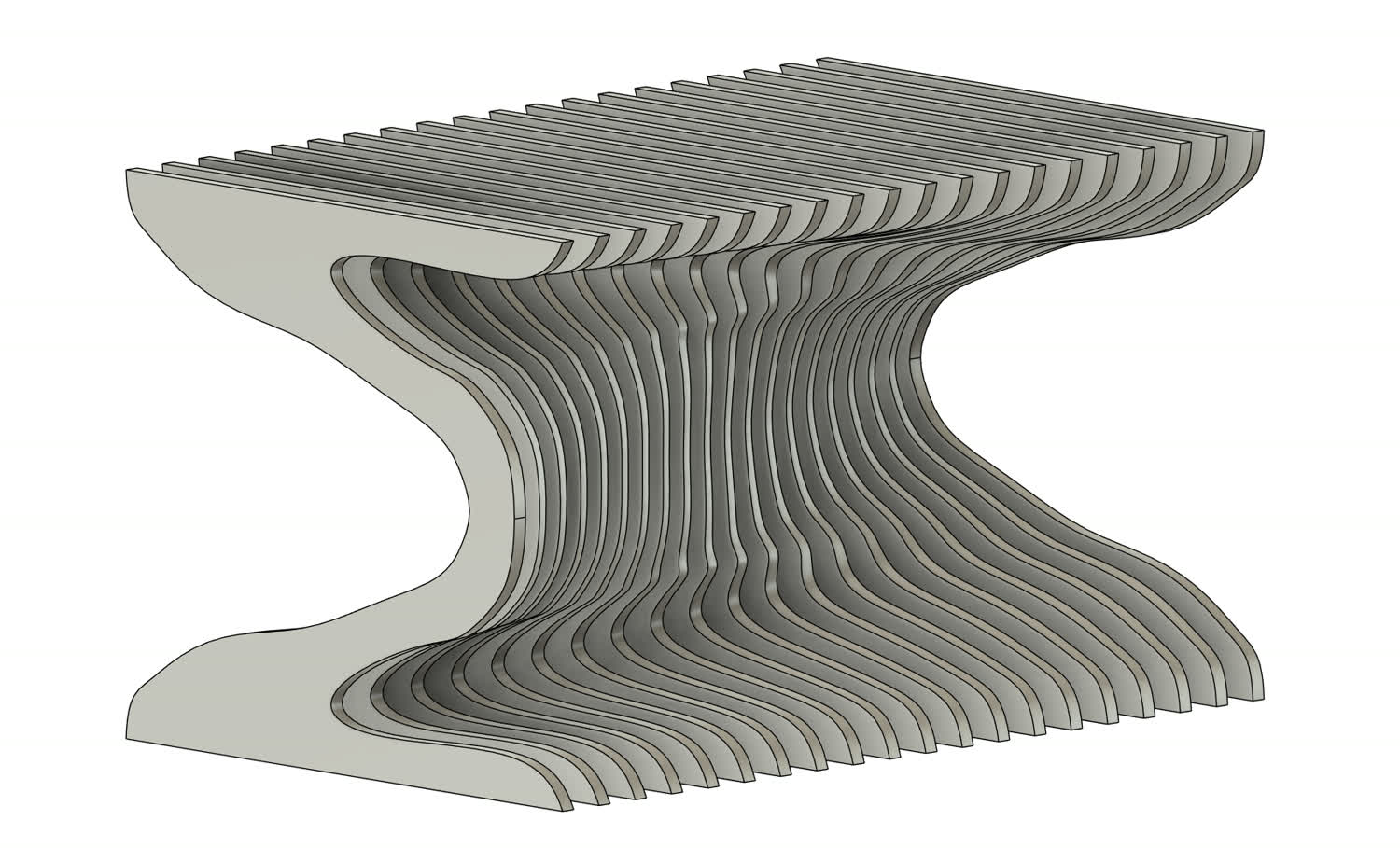
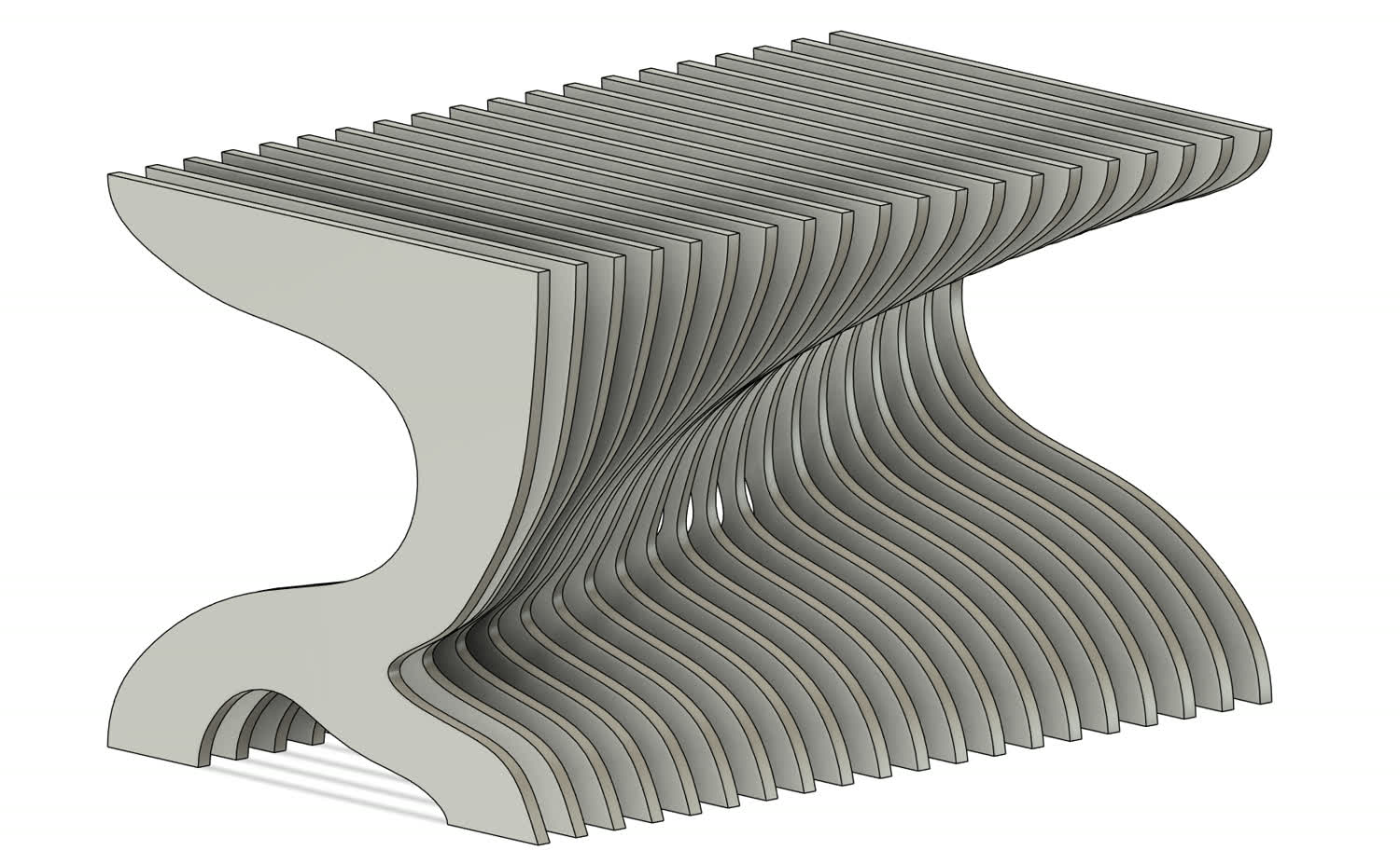
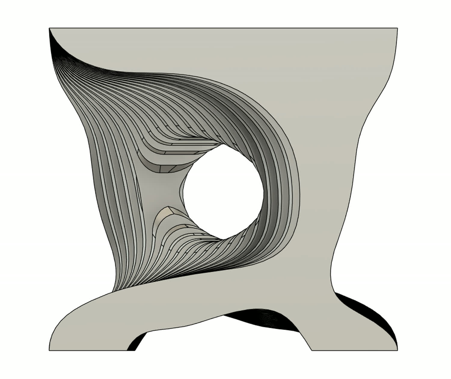
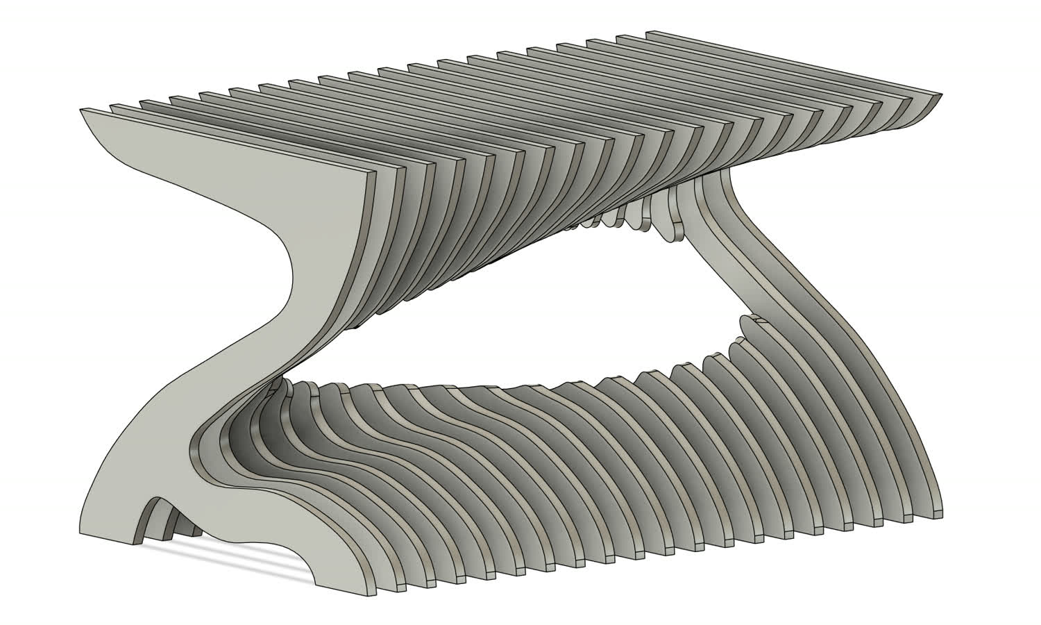
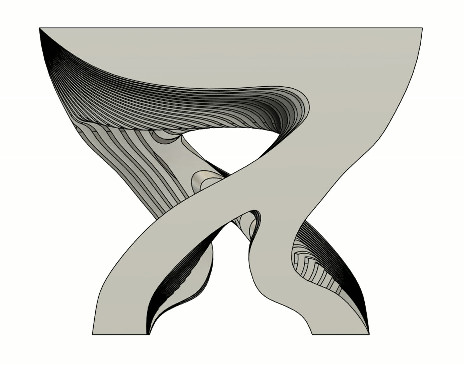
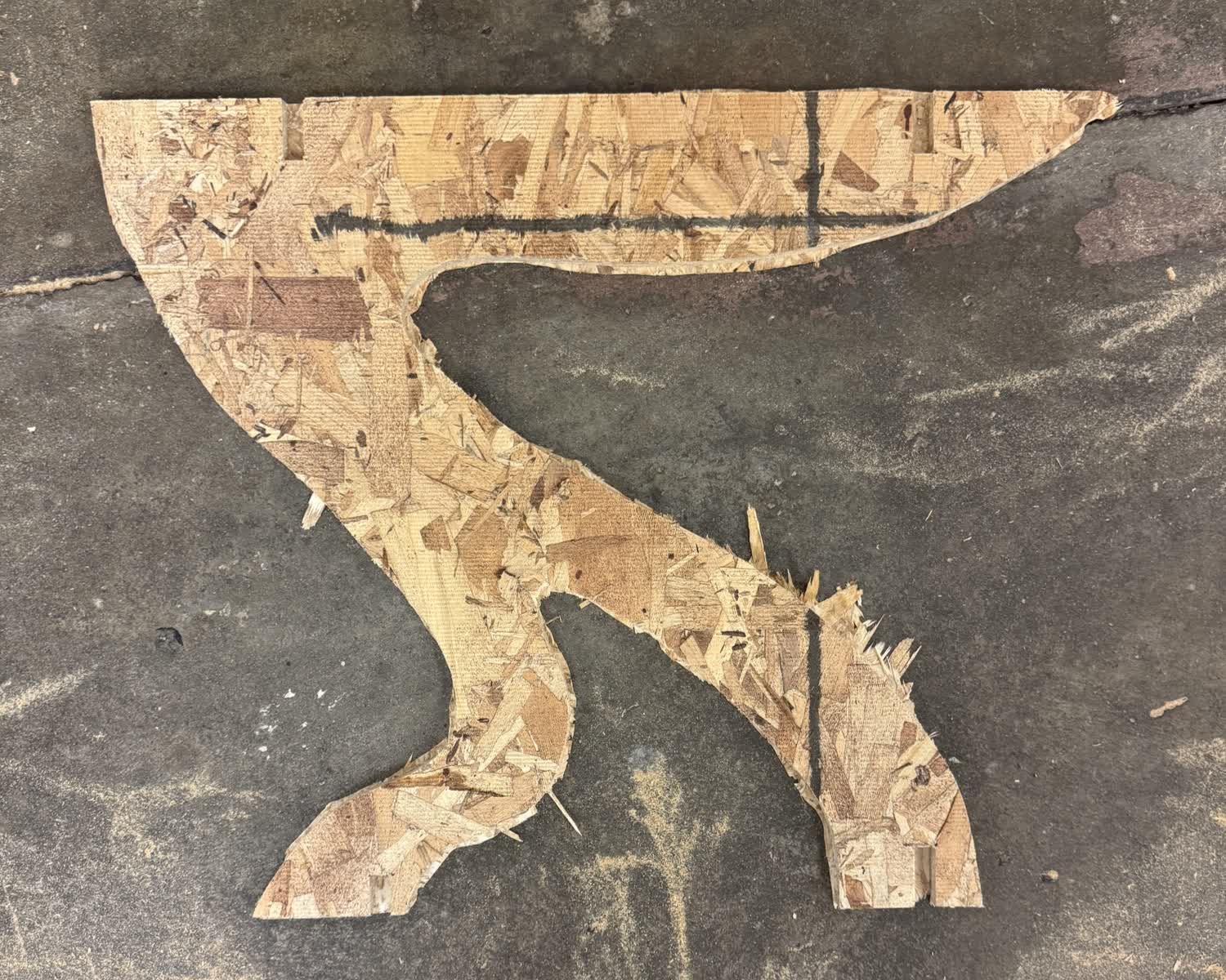
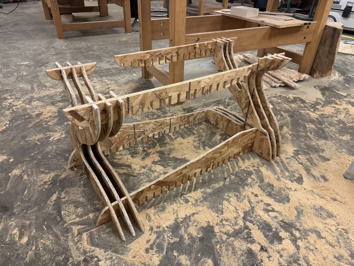
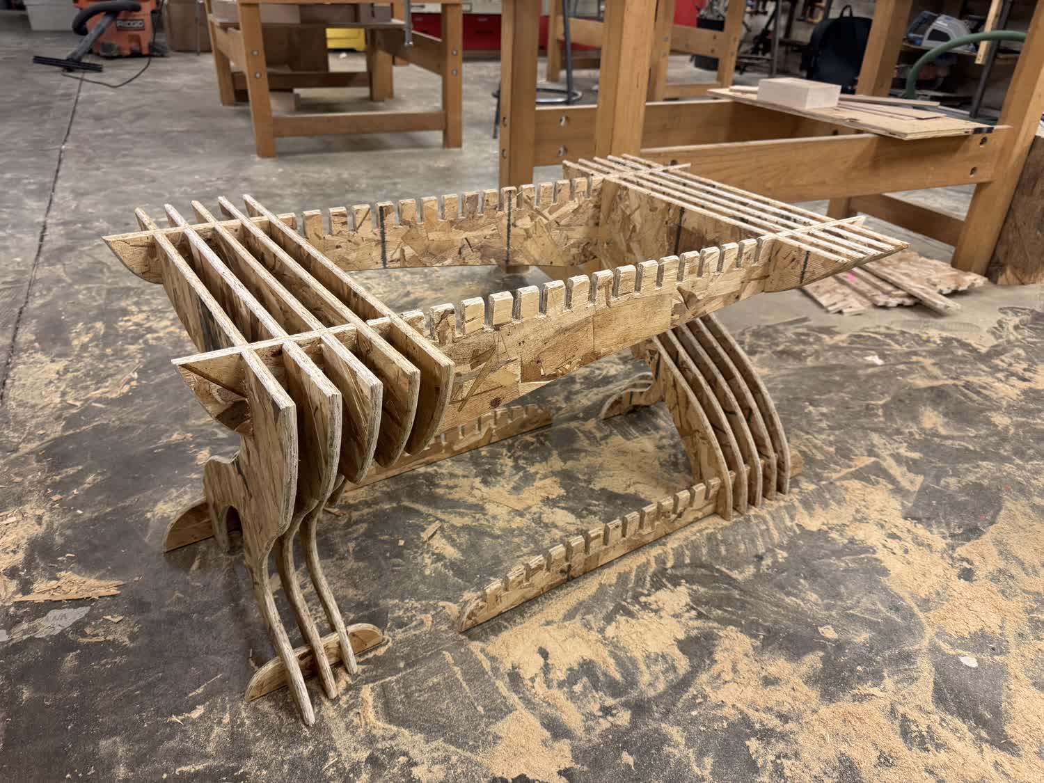
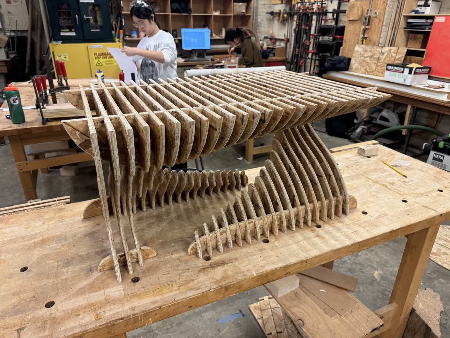
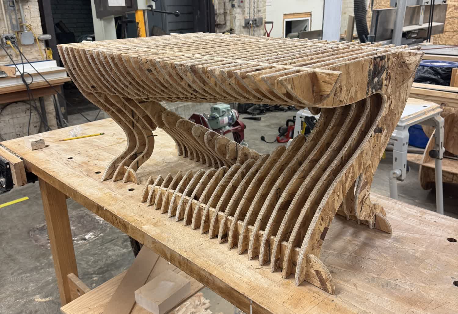
The final design that I ended up choosing was interesting, as I tried lofting through the middle of the sketch as opposed to simply cutting ovals through them, as you can see in designs 4 and 5.
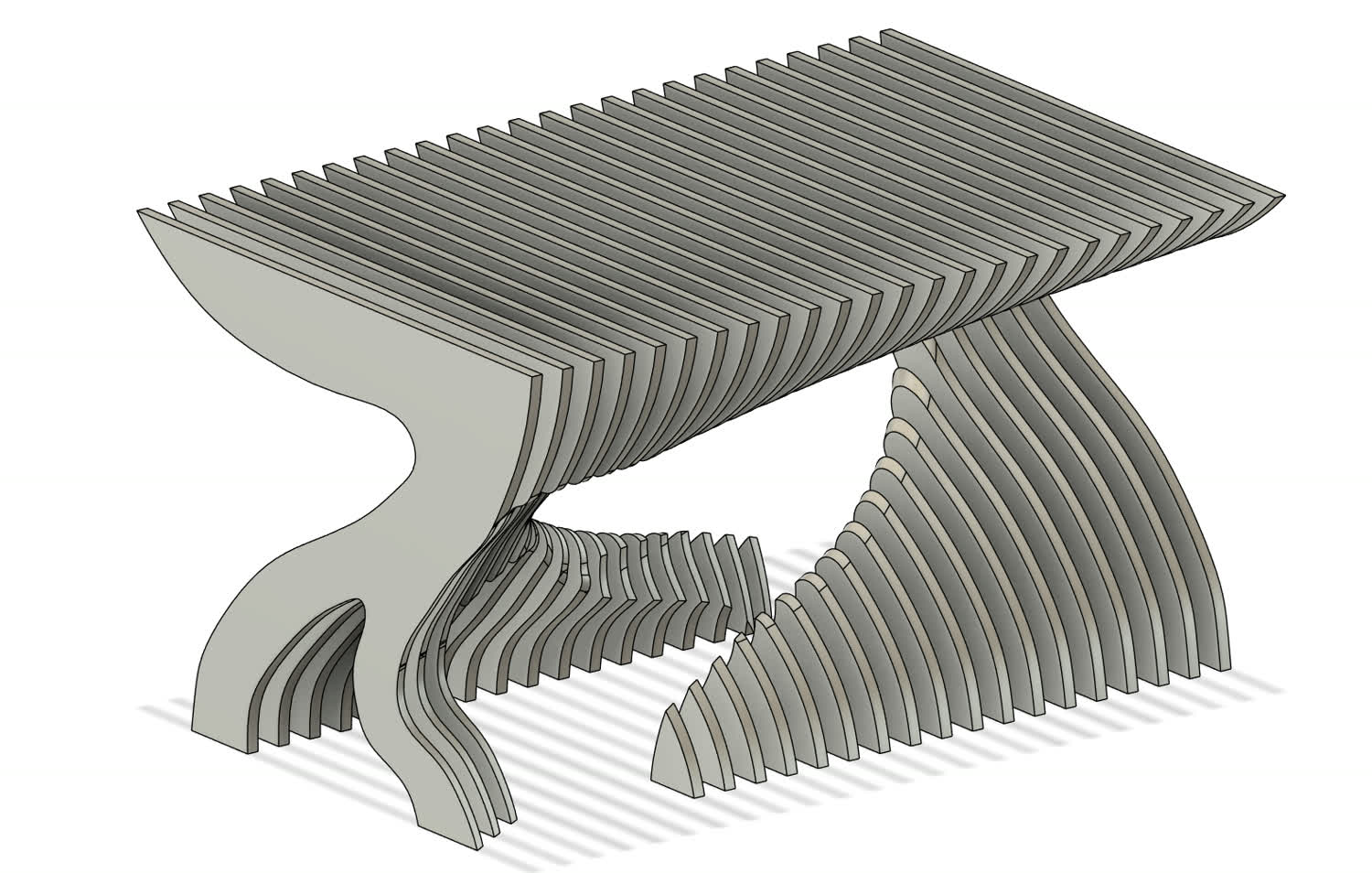
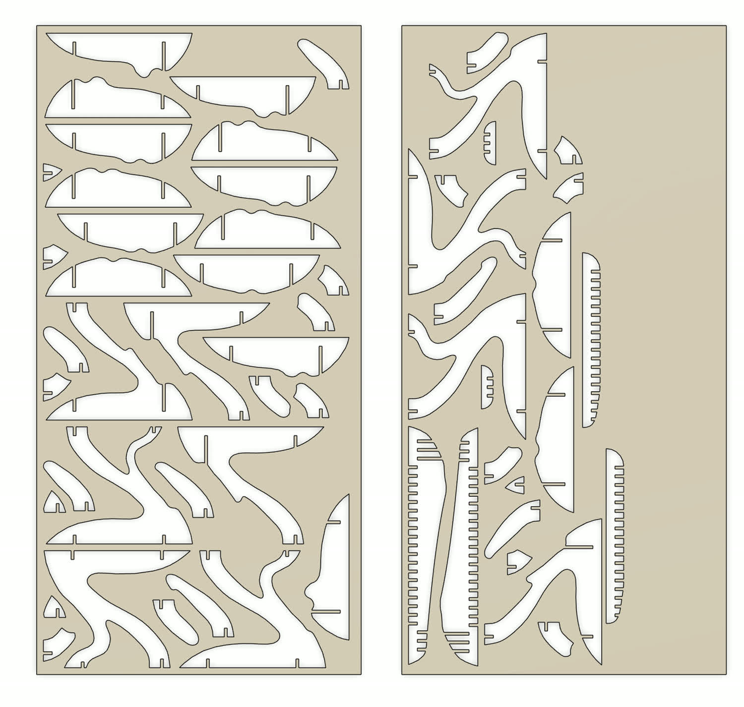

Once the files were prepared for the Onsrud, the cutting process was actually quite simple. Due to the quality of the machine, there was little concern for failure, and so I simply waited for the cuts to be done.
Post Processing
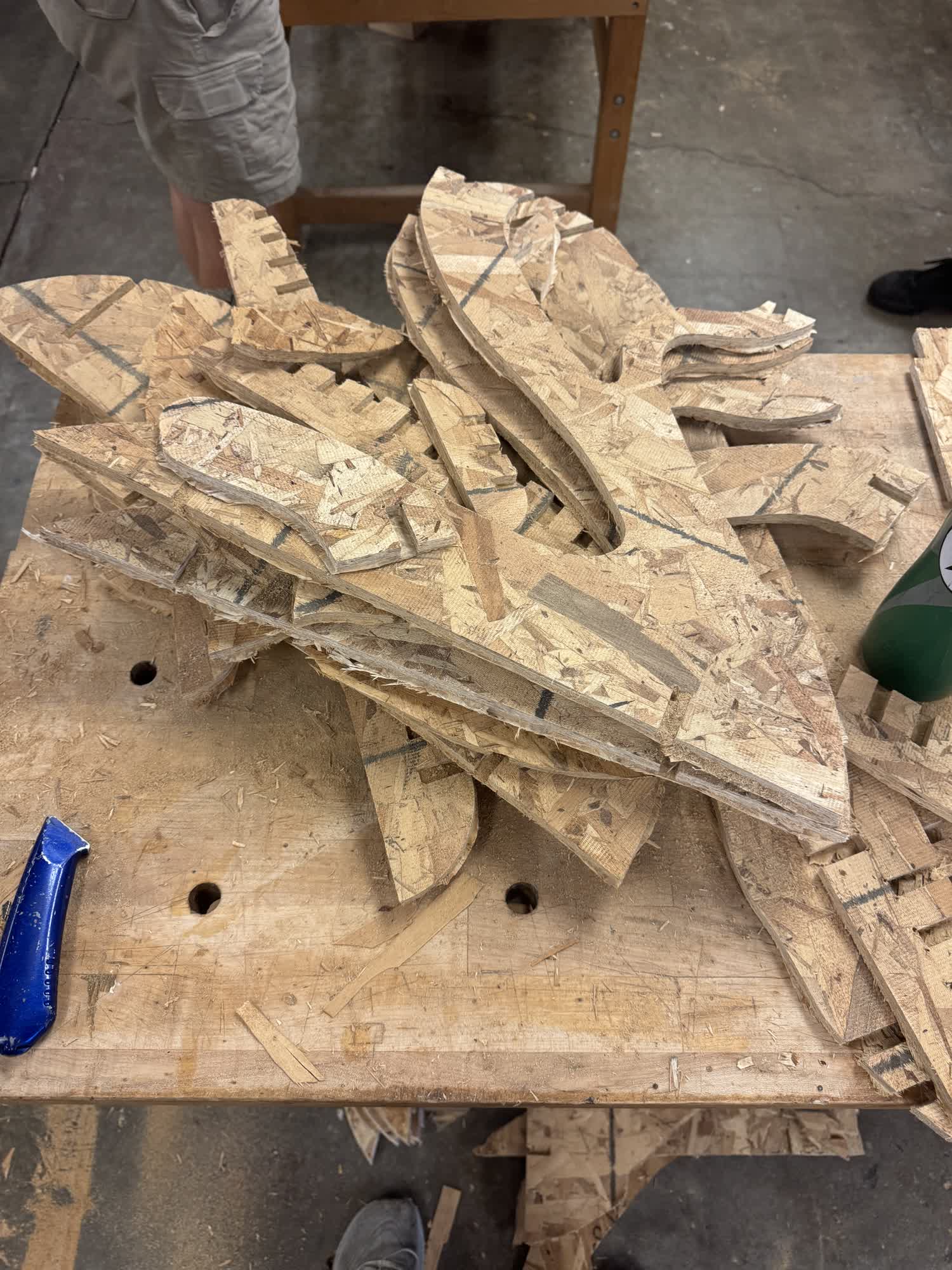
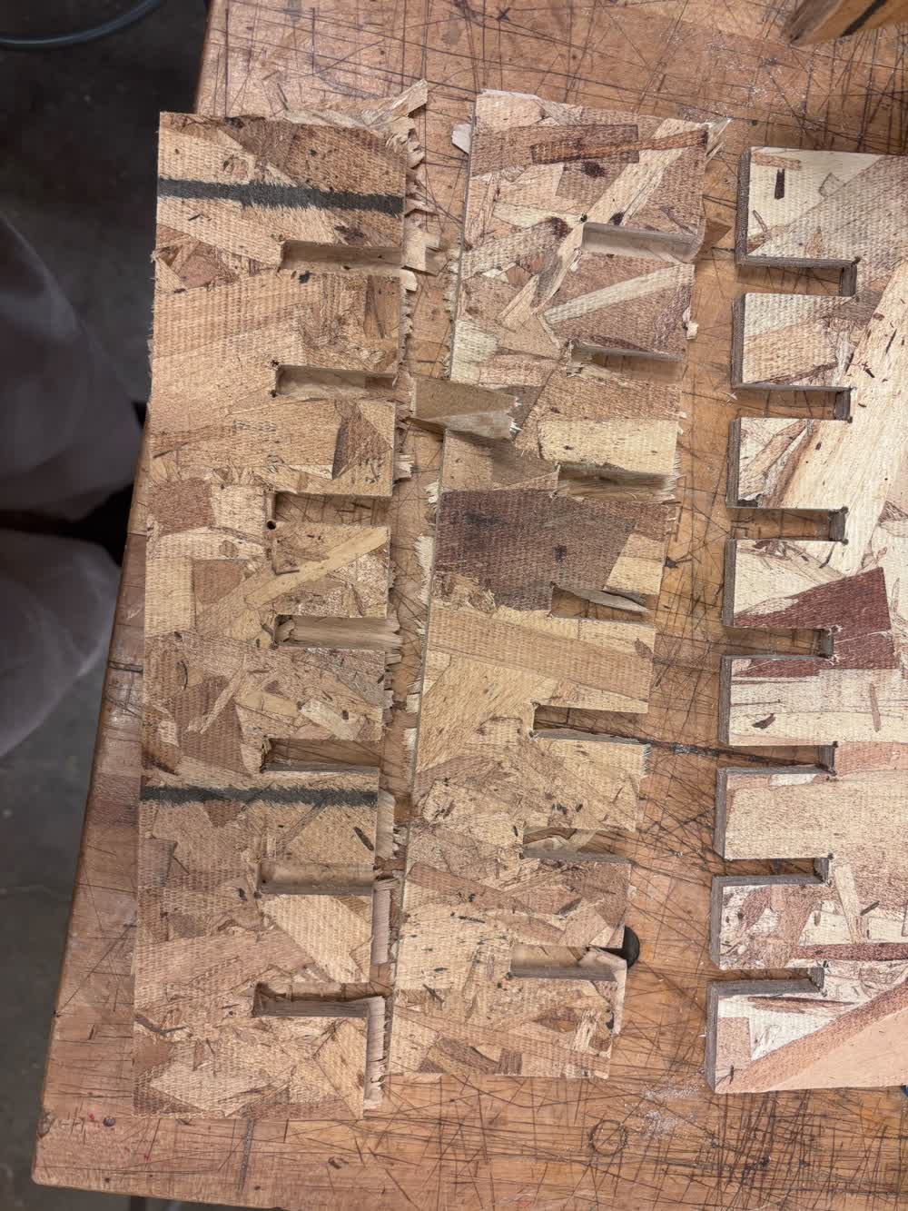
The other form of post-processing that I had to do was to remove the onion skin from the dogbones in each component. To do so, I simply used a box cutter and cut the material out.
Thoughts and Reflection
This week was a lot. I started modeling different tables on Thursday, and yet somehow I found myself in the wood shop from 12–7:30 on Tuesday, cramming to try and get it all in.
I was gone over the weekend, which is why I had to cram, but nonetheless, it was stressful.
I'm super happy with the result and how the project turned out in the end. I swung through a range of emotions throughout the process. Originally, once I modeled the slats, I was
super excited with the design. Once I added the supports to actually attach them all, I thought they ruined the design and I was quite disappointed. I told myself that it didn't matter
at that point and I just needed to move on and get the project done. Then I went to cut it all out and assemble it, and I swung all the way back and was super happy with the design.
I found myself really enjoying using the router table; I found it quite satisfying to take such a rough part and drastically improve its appearance and feel.
As for the design itself, I am glad that I decided to go with the contour slats. For one, I think it turned out quite nice—I really like the organic shapes that came out of the
modeling process. Importantly, the table is stable, and I think it can withstand living in a fraternity house, unlike a tensegrity table. I was even able to sit on it (it looks an awful lot
like a bench).
It would be cool, once I have more time, to go back through the process, refine the design, and make it out of nicer wood to serve as a proper coffee table.