This week is all about output devices, which include LEDs, displays, motors, speakers, and solenoids. Although many of these are interesting to me, the one that will be most useful for what I'm thinking of making for my final project is the motor. I have a little experience with controlling stepper motors using a board Jake designed and adapting code from Quentin, but I haven't designed a PCB for them myself, so I wanted to give that a shot. I started by looking through a simple tutorial on how to drive a stepper motor and learned how to make a dual H-bridge circuit in KiCAD. To make sure I kept my focus on getting the motor motion to actually work, I opted to use one of the drivers we had in stock instead of my own H-bridge. We have these available: DRV8428PWPR and this DRV8847PWPR. I'm opting to use the DRV8428PWPR because it appears to be more precise and allow for finer microstepping.
I am checking the inventory to see which components are available to put them into my circuit design in KiCAD. I am also referring to Neil's resources on the DRV8428 and a few HTMAA former assignments like this one. When I checked for the driver, I saw just how thin the pins are and realized it would be beyond the Carvera's capabilities to make a circuit that precise. I don't think I'll have a chance to coordinate with a TA to teach me the laser method of PCB production, so I'm going to need to pivot to something else.
Although it's not strictly necessary, it would be nice if my ruling engine could have a display that would act as a selector screen for diffraction grating line spacing, length, and count. I'll try moving forward with this idea for now. As it turns out, the components I would need to make this happen are missing in the inventory. Given that I've already wasted so much time trying to make these two directions work, I'm going to go with something simple that is sure to have parts available. That is using LEDs to do charlieplexing, which was a concept that intrigued me from the lecture. I'll look into this next.
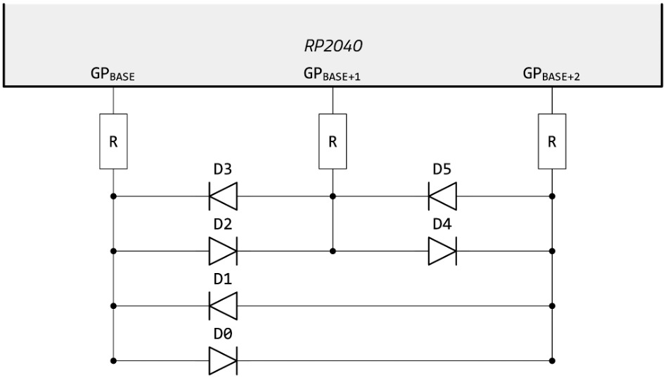
I am looking through some charlieplexing resources like this gitlab page, this test Arduino code, and this Instructables. Next I'll design a simple circuit to do this. The number of pins should equal the number of resistors, and the resistor values should be half the resistance required to classically drive a single LED. In my case for the white LEDs in stock, I set this to 50 Ohms.
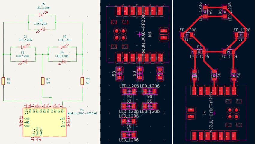
This TinkerCAD page for two pins and three pins are a good starting point to reference. I most heavily relied on the schematics on this github page to understand how everything would need to be laid out. I placed all my components (three 50 Ohm resistors in a 1206 package, six white LEDs in a 1206 package, and one Seeed Xiao RP2040) and connected everything together. I made sure to use digital pins (D0, D3, and D6). I updated the Seeed Xiao RP2040 footprint to not have holes and made both traces and required spacing between traces 0.6mm, an increase from my previous boards. Here is the helpful image from the github page followed by my schematic and layout. I wanted mine to look somewhat interesting so I arranged it into a smiley face once I got the basic layout figured out.
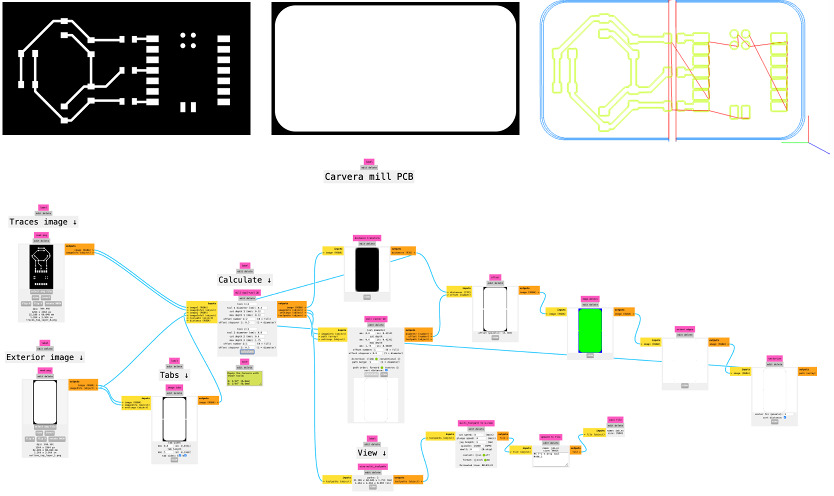
I ran a design rule check to make sure everything looked good and then exported the gerber files for F.Cu and Edge Cuts. I think because my outline was particuarly curved, I had an issue getting gerber2img to work for the Edge Cuts. I asked for help, and Ceci directed me to gerber2png which worked perfectly. Here are the trace and edge cut images as well as the associated mods process and outputs.
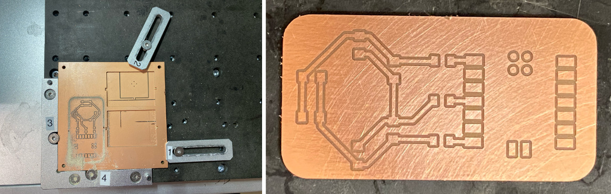
Then I set up the job on the Carvera and secured my stock. The first time around, the traces were not completely cut away in all parts, and it seemed that one side of the board was cut much more harshly than the other. I assume this is because the piece of stock was large and bowed. Here is that board after sanding.
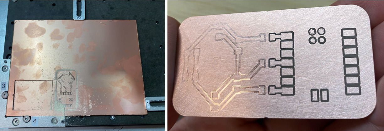 I ended up switching to a much smaller stock and remilling to get it right. This turned out much better. I sanded it to achieve a smoother finish and was happy with the result.
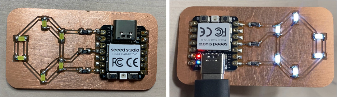
Next I assembled the board, making sure that the LEDs were facing the correct directions, and tested it. I asked ChatGPT to come up with some simple code for me including code for flashing the Seeed Xiao RP2040, letting it know what pins were used, the resistor values, and what I wanted to have happen. Here is my ChatGPT prompt where I pseudocoded this out, which generated perfectly usable code in Arduino to test and demonstrate that the charlieplexing was successful! Here is the assembled board followed by a video of it in action. I'm glad I ended up making it look like a smiley face, because it feels like it has a purpose.
All in all, I think this week went okay. I learned something new, but I had really wanted to get through the motor control hurdle that I'll need to overcome for the final project. This week it just wasn't possible for me to do that because of time and not knowing how to use the laser PCB fab process, but I know I'll need to do this to move forward with other things soon. I'll check with some of the TAs during office hours to see if they can help. In terms of the charlieplexing though, I like how it turned out: a simple board that taught me something.
I ended up doing the group assignment with Dimitar, and we looked at a stepper motor (gearboxed NEMA8) and a DC motor. I added a write-up of this to our group site for the week.