For my final project, I would like to make a ruling engine. This is a precision machine that rules (or engraves) fine lines into a surface and is often used to create diffraction gratings. I am starting by reading through some papers and looking at similar projects others have worked on.
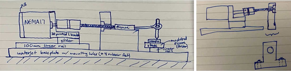
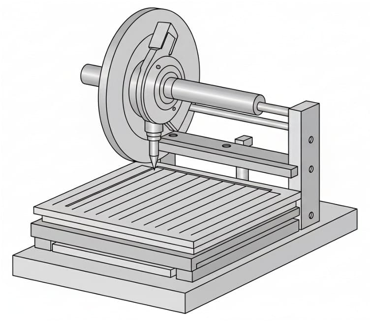
I met with Quentin to talk through my plans for the project, and it appears that it the ruling machine would have the best chance at working if I were to decouple the diamond scribe's motion from the sample's. I can use a diamond scribe on a wheel plus a way of moving the sample perpendicularly to the grating lines, perhaps using a single-axis flexure (maybe with a piezo stage). Zach's machine building class project is a good source for inspiration here. What is important here is to have a closed feedback loop for positioning so that there is high repeatability, even if small adjustments need to be made after the initial motion, and using a flexible mechanism will allow for much greater precision than a leadscrew. I aim to make very small but functional grating. In case you're curious, I will add my messier pre-Quentin-meeting documentation in Ruling Machine Planning. Here is some concept art I made using whisk.fx.
Achieving precision motion is one of the most interesting parts of the ruling engine to me. Therefore, I will aim to complete a precision xy motion stage first, and if I can do this quickly, will then try to figure out how to add the ruling capability as a stretch goal. Achieving the precision needed to make a diffraction grating with lines consistently spaced just a few micron apart is very challenging, and I've done a lot of brainstorming on that problem.

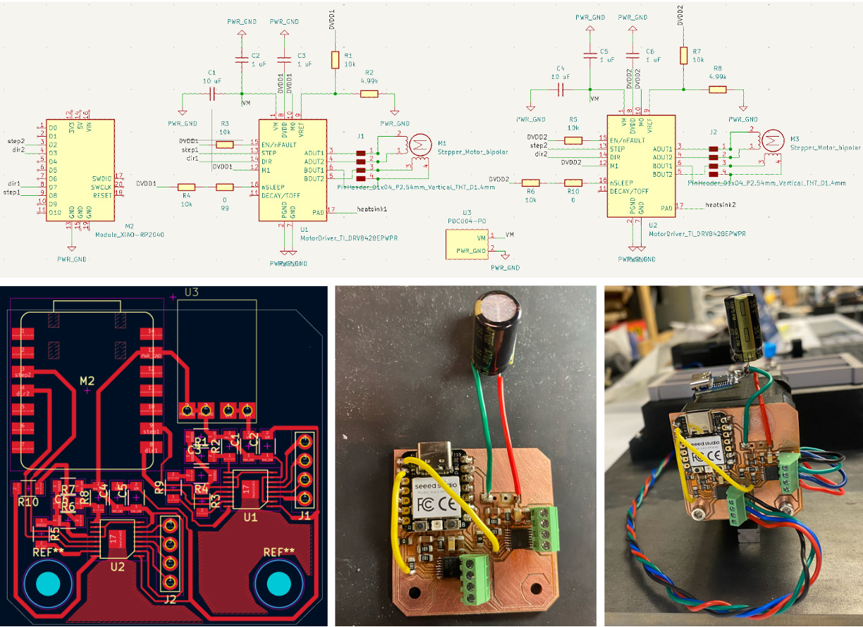
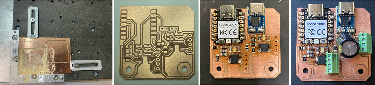
I have begun ordering parts for this and planning it out more concretely, keeping a BOM internally to keep track (this will be posted once its complete). Today (11/26) I am working on designing the motor control board. I am referencing Anderson Zelarayan's Output Devices Week to get an idea of how to use the DRV8428PWPR motor driver to drive a NEMA17 stepper motor, which alerted me to an example in the datasheet that enables 1/8 microstepping. I'll start by trying to replicate this. It seems to be possible using the Carvera but I may need to use the laser.
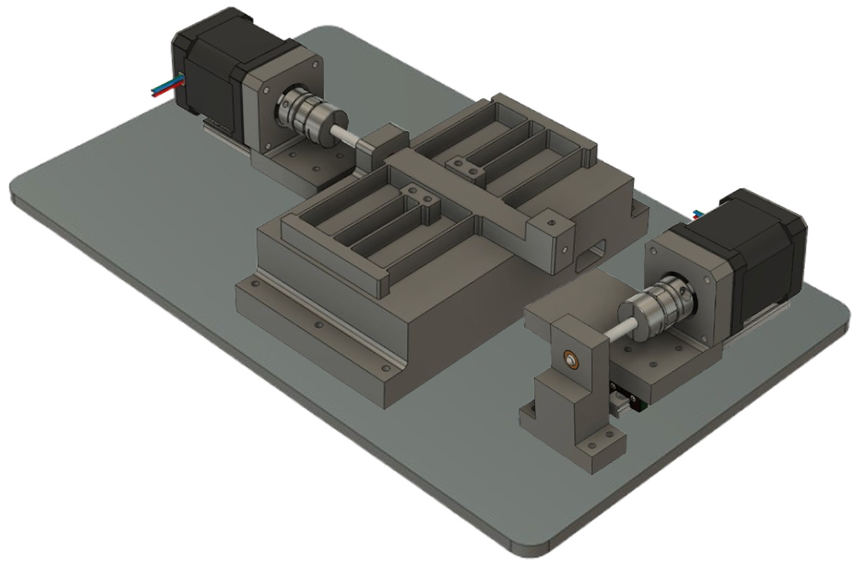
The ruling engine I made uses two stepper motors and two precision screws to move a diamond scribe along the surface of a blank (with a calculated 158.75 nm microstep size). In short, it scribes thinly-spaced lines into flat materials. If these lines can be spaced close enough together, this ruling engine can be used to make diffraction gratings, which it was able to do with as small as 5um spacing thus far.
Ruling engines have been around for a long time. A good history of them as they relate to MIT is presented in A Brief History of Gratings and the Making of the MIT Nanoruler. Ruling engines have been used for over a century to cut ultra-precise line gratings for spectroscopy and optical metrology. More recently, similar results are often achieved with CNC motion plus feedback control, or replaced entirely by lithography-style grating fabrication.
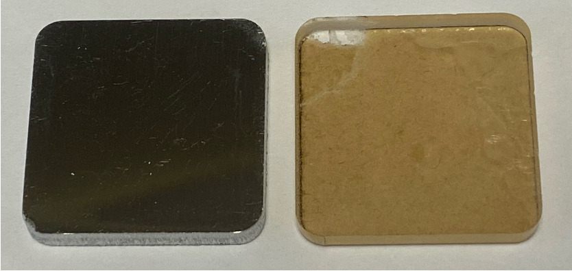
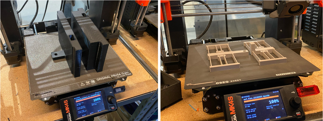
Many of the materials and components used to make the ruling engine were in the class inventory or the Mars Lab. I therefore used part prices from the inventory for my BOM and found similar items to approximate the cost of other items with less obvious origins (indicated by an asterisk). Anything with "Arrived" next to it was ordered by me. Everything else was already available or had been previously ordered (in the case of the hex screws and bushings). I have an Excel spreadsheet where I include materials, components, origin, and cost. In short, PETG was used for 3D prints, polished aluminum and acrylic for blanks, acrylic for practice baseplate, steel for actual baseplate, precision screws (2) and bushings (2), PCB with components and wiring, screws, washers, and nuts. The couplers and spider were the most expensive, and I have previously made 3D printed alternatives I'd like to adapt to bring down the cost in future. Here is the reproduced table.
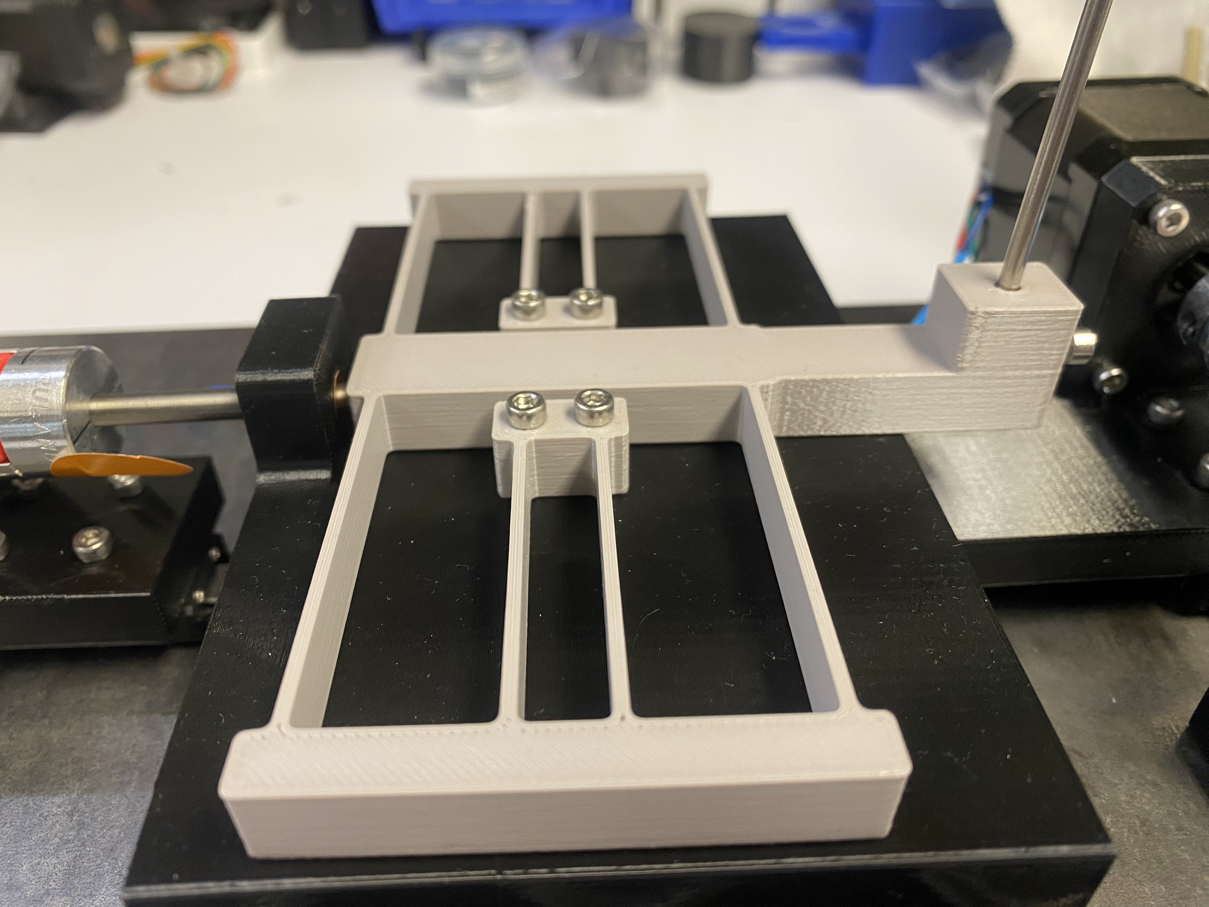
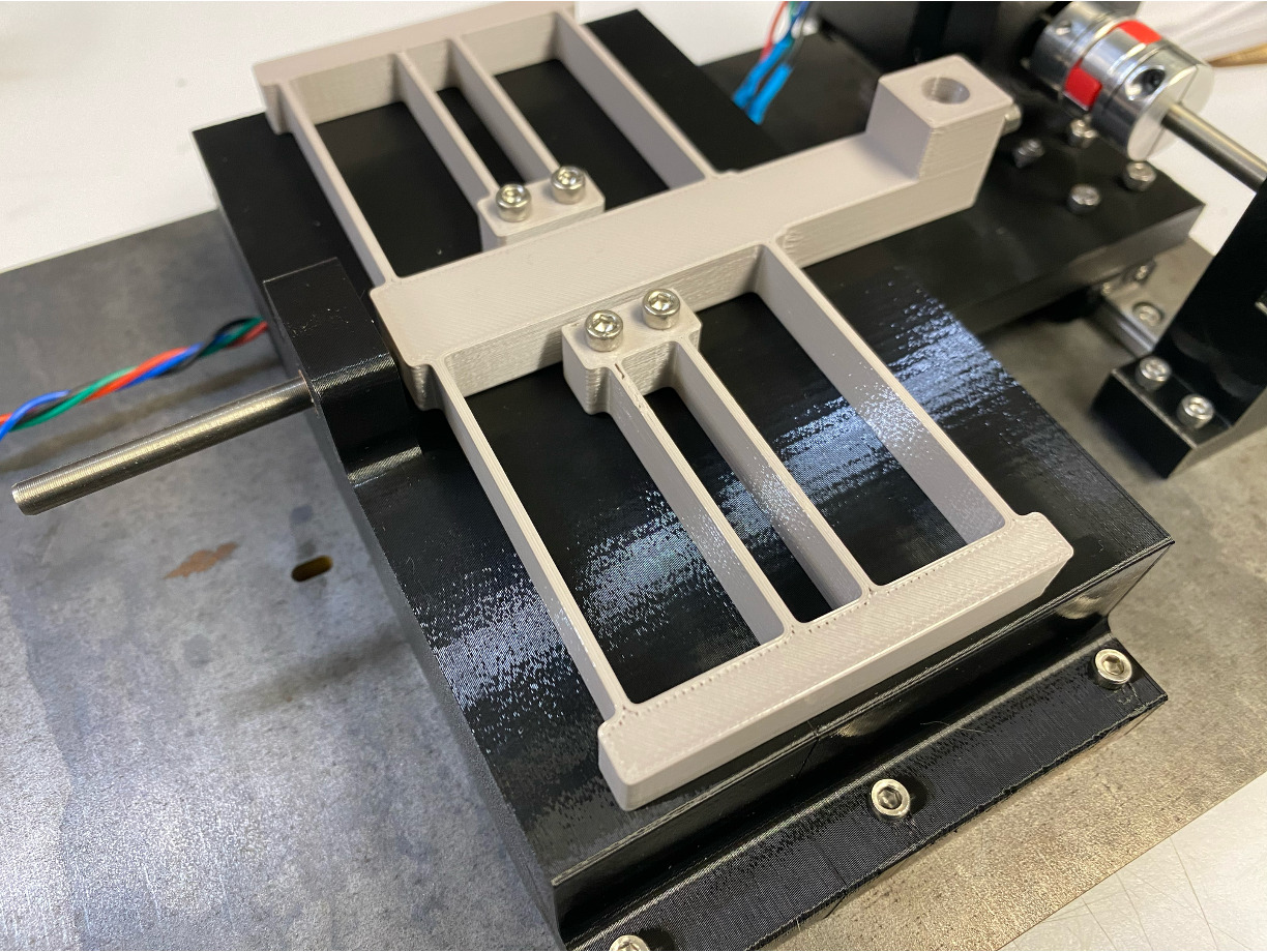
There was a lot of testing, iteration, and retesting throughout the course of the project. In the end, what worked was the motors could repeatedly drive the shaft-coupled precision hex screws through the two respective bushings. For the line-spacing (x) axis of motion, the bushing successfully pushed the linear flexure (which was inherently springloaded) in the desired increments. The y axis successfully translated the platform that supported the sample blank along the y axis, scribing it. The scribe holder portion of the flexure held it in place well, and the steel baseplate with rubber feet sufficiently stabilized the system to enable the production of diffraction gratings.
Here is a zoomed-in view of it ruling acrylic.
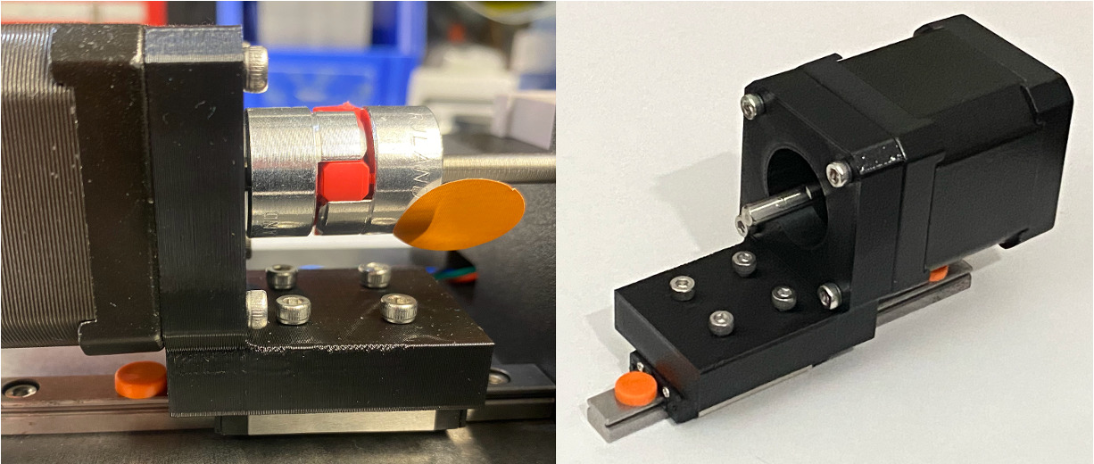
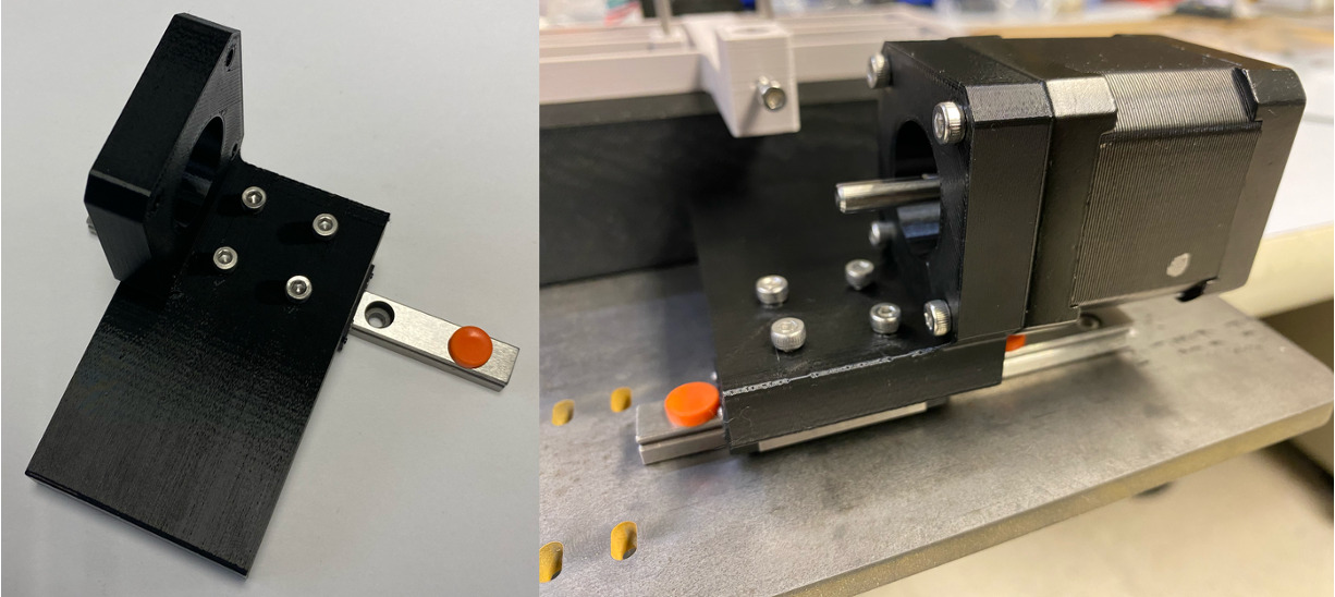
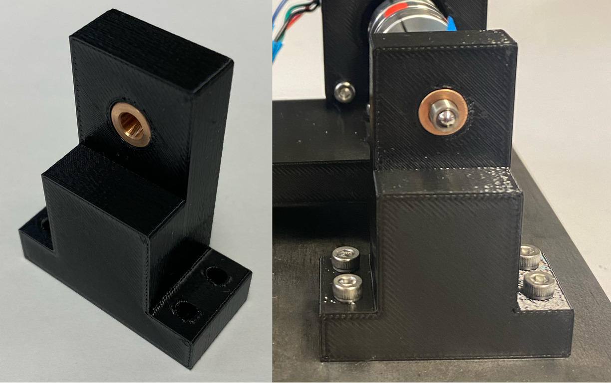
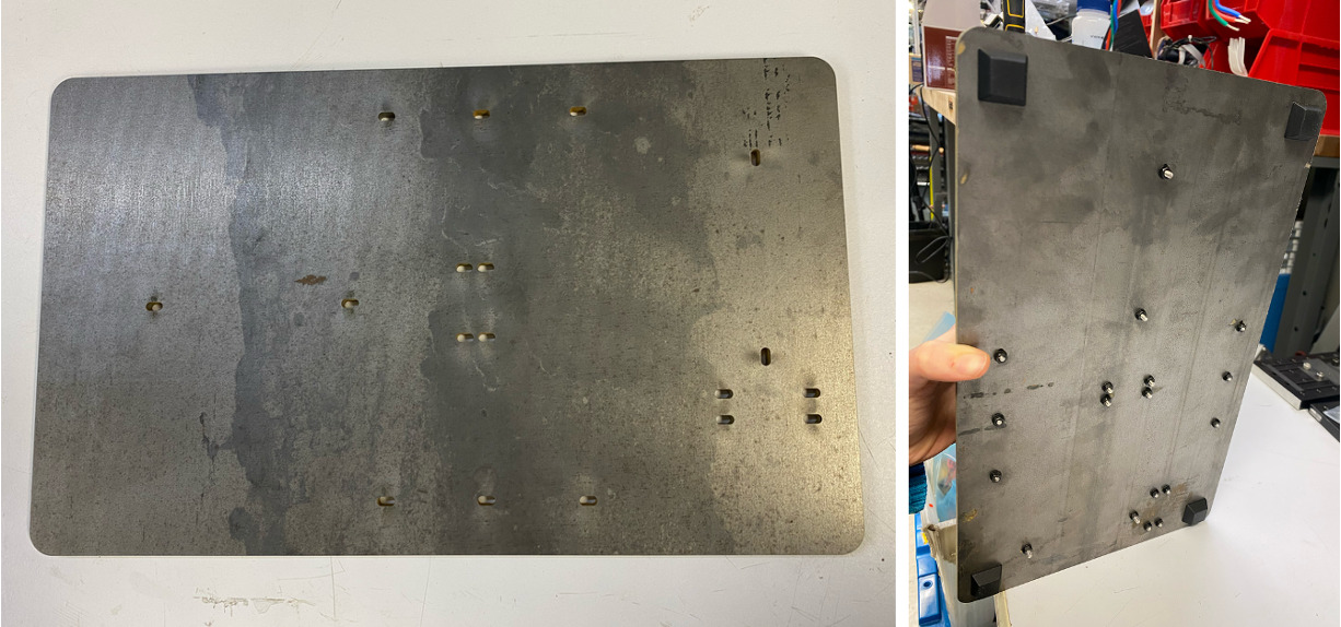
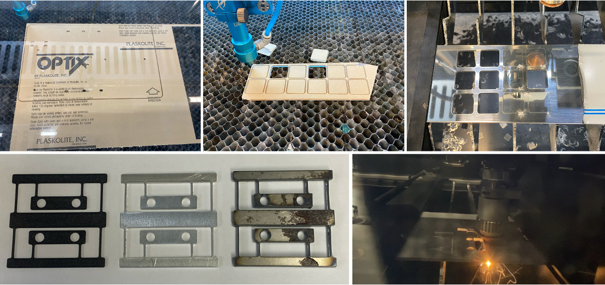
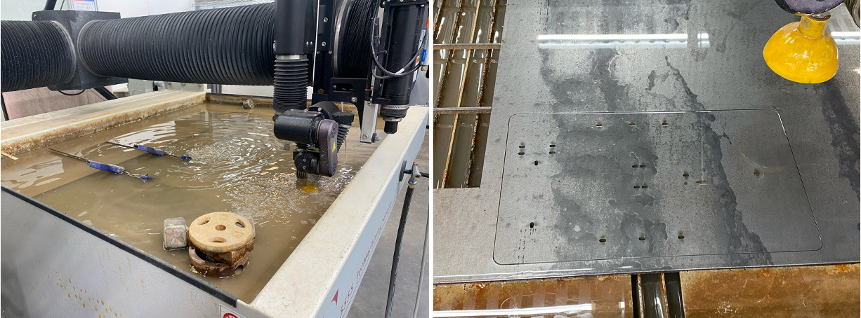
Now for what didn't work, there was plenty. On the electronics side, I spent a long time routing and adjusting settings on the Carvera to get the DRV8428PWPR motor driver footprint and associated traces to be properly cut out. I ended up telling mods the tool was 0.34mm in diameter rather than 0.4mm so it would allow me to override its built-in operating constraints. After struggling with electronics assembly (which required steady hands and lots of solder paste), testing the motor revealed to me that I had missed something crucial (on page 25 of the driver datasheet), that the ENABLE pin needs to be driven externally to drive it HIGH. I fixed this using jumper wires for each of the two drivers and also reconnected the decoy that had broken off due to torque, gluing down the wires to prevent future problems. I iterated on flexure designs as well, initially laser cutting aluminum and steel with the MetalFab. As it turns out, aluminum plastically deforms quite easily at small thicknesses, and steel was too stiff to give me the larger travel distance I wanted. Slag also caused some of the polished aluminum blanks to not be cleanly separated from the larger piece. The ones that did separate needed to be filed to be flat when mounted with double sided tape. Other than that, some inconsistencies between online CAD file dimensions for the off-the-shelf components I was working with came up, such as the 100mm linear rail file being longer than 100mm. This led my test baseplate laser cut out of acrylic to have incorrectly placed slots, which I fixed in version 2 which I water jet out of steel. In addition, I found out after partially assembling one of the axes that the screws that go through the linear slides need to be added before mounting the motor, so I needed to disassembly and reassemble that. Initially I was going to use a diamond-tipped scribe that comes in a pen form factor, but after mounting it in the flexure, I learned that the pen casing did not constrain the motion of the diamond-tipped refill inside it, making it wobble. Therefore I switched to clamping the refill directly which constrained the motion just fine. Beyond this, I designed the motor-to-linear-slide mounts to be exactly the height that would cause the screws to bottom out. I later learned from Jake that this was preventing the cap head screws from clamping down on the 3D printed part, leading to wobbling, so I added in some washers to fix this. Many thanks to Jake for helping out throughout the project with answering questions and helping think through early designs. The final issue which remains to be addressed is that the platform that supports the sample wobbles sways up and down in response to the motor revolutions. I realized that I didn't brace the platform with diagonal supports between it and the portion of the 3D print connected to the motor. This will be revised in future iterations of this project. I will also try to scribe lines that are even closer together to try to yield a more apparent rainbow effect in the gratings. I am also going to consider using a different end effector to attempt to improve the cleanness of the cuts. The SEM images look rather messy. Cleaning off the debris is another next step (perhaps with IPA for the aluminum).
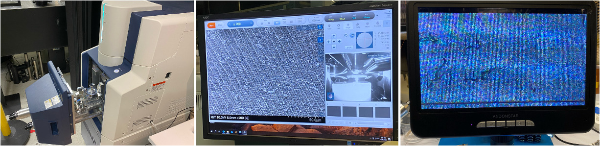
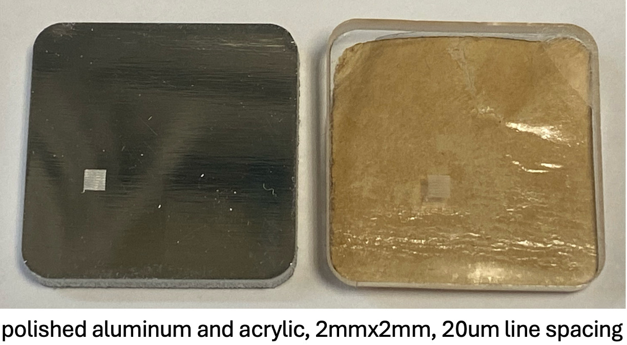
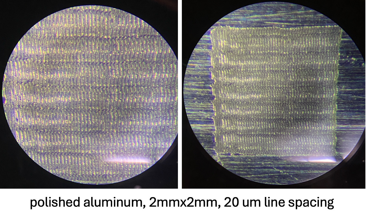
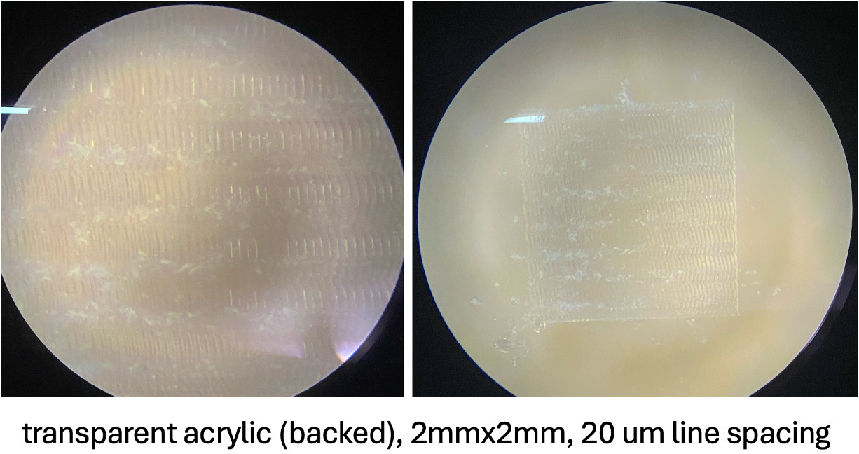
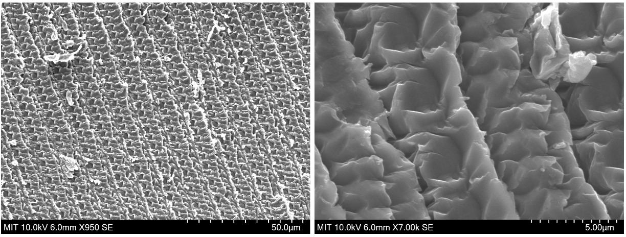
I ruled samples of polished aluminum and acrylic with 20um line spacing and with 5um line spacing. Following this, I looked at the ruled samples under a microscope and then used our FlexSEM 1000 to take some SEM images of a 5um-line-spacing polished aluminum sample. The SEM image confirmed that the line spacing is ~5um (see the scale bar), showed that indeed each motor revolution corresponded to an undulation in the line (which can also be seen in the colorful microscope images), and revealed unexpected surface features (stippling) that are likely caused by the motion's stepwise nature (discrete microstepping with the NEMA17 paired with audible motor vibrations). I also was able to see rainbow patterns when shining a light on the surface at certain angles, confirming that the line spacing is sufficiently small to transform my samples into visible-light diffraction gratings. Smaller line spacing will happen soon!
This is the 20um-line-spacing polished aluminum.
This is the 20um-line-spacing acrylic.
These are SEM images of the 5um-line-spacing polished aluminum.
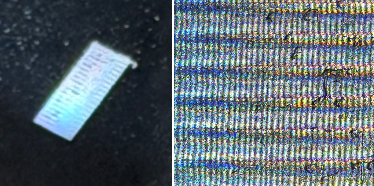
This is the 5um-line-spacing polished aluminum captured using a zoomed-in camera image (left) showing the diffraction grating with its characteristic rainbow coloration, and a microscope image (right) with bluer colors on the left and redder ones on the right, with some debris on the surface and discrete vertical grated lines.
Using my ruling engine, I can make diffraction gratings with a line spacing of 5um (or below — more testing to come). This can be used for reflective surfaces and transparent ones to make bothreflective and transmission gratings. I plan to push the limits of the system and go for 1um line spacing next, since the motion system is capable of ~150nm per microstep. The line spacing limitation will likely be the sharpness (diameter) of the diamond-tipped scribe I'm using. Diffraction gratings like these can be used in spectrometers and other optical instruments to direct the wavelength components of light into unique output angles, thereby separating the light to enable various forms of metrology. All in all, I am very happy with how this turned out and am excited for what lies ahead! Thank you to everyone who supported me throughout the process.