Mechanical &
Machine Design
Collaborative machine building project with the entire EECS class to design, build, and automate a complete mechanical system with mechanism, actuation, automation, function, and user interface.
- Group Assignment 1: Design a machine that includes mechanism + actuation + automation + function + user interface. Build the mechanical parts and operate it manually.
- Group Assignment 2: Actuate and automate your machine. Prepare a demonstration of your machines for the next class.
- Individual: Document your individual contribution to the group project.
01 · Project Overview
This assignment was a collaborative effort involving the entire EECS class, where we worked together to design and build a complete automated machine. The project focused on integrating mechanical design principles with actuation systems, automation, and user interfaces to create a functional machine capable of performing specific tasks.
Machine Concept: BrainrotBot
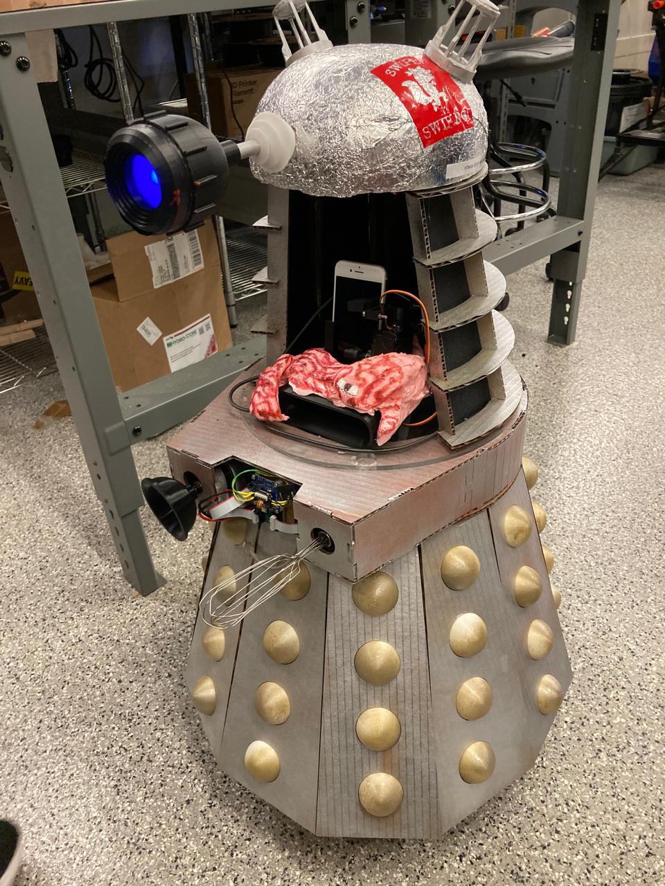
The class developed a mobile robot system called BrainrotBot (also referred to as Brainrot9000) — an autonomous machine that navigates and interacts with smartphones. The machine combines multiple subsystems including person tracking, phone interaction mechanisms, and automated control systems.
- Mechanism: Phone holder with integrated tapping and swiping mechanisms
- Actuation: Servo motors and linear actuators for precise control
- Automation: Edge AI face detection and person following system
- Function: Automated smartphone interaction (tapping, swiping, scrolling)
- User Interface: Camera livestream and control dashboard
02 · Subsystem Architecture
The machine was designed as a modular system with distinct subsystems, enabling parallel development and clear integration points. Each subsystem had defined interfaces and responsibilities.
Subsystem Breakdown
| Subsystem | Components | Function |
|---|---|---|
| Subsystem A | Scroller arm, phone holder, sound funnel | Platform for phone mounting with scrolling arm and 3D-printed sound amplification |
| Subsystem B | Camera, sensors, drive control | Camera/sensor system outputting desired position changes for navigation |
| Subsystem C | Movement/Roomba base, drive train | Drive actuation with wheels and motor control for mobility |
| Subsystem D | Door mechanism, outer body | Dalek facade with opening door mechanism for access |
| Subsystem E | Internal column, Roomba base | Structural platform supporting all components |
| Subsystem F | Audio PCB, amplifier | Audio system with PCB and 3D-printable impedance matching amplifier horn |
03 · Key Mechanical Components
Phone Holder & Amplifier
A spring-loaded phone holder with integrated passive amplifier was designed for secure phone mounting and enhanced audio output. The design incorporates a horn-shaped amplifier for better sound projection from the phone speaker.
- Spring-loaded mechanism: Ensures secure phone mounting with easy insertion and removal
- Passive amplifier: Horn-shaped design amplifies sound without electronics
- 3D-printed components: Custom-designed holder and amplifier horn
Tapping & Swiping Mechanisms
The machine includes servo-driven linear actuators for precise tapping and swiping gestures on the phone screen. Two MG90S micro servos control synchronized motion patterns.
- Linear actuator system: Converts rotary servo motion to linear motion for precise control
- Synchronized operation: Dual servos work in coordination for tapping and swiping
- Motion patterns: 4-step synchronized sequences (0° → 90° → 180° → 90° → 0°)
Stylus Mechanism
Multiple iterations of stylus mechanisms were developed, progressing from manual designs to a linear actuator-driven system for precise touch screen interaction.
- Stylus v1.1: Basic touch screen interaction with manual positioning
- Stylus v1.2: Refined version with improved contact mechanism
- Stylus v2: Enhanced precision and repeatability
- Stylus v3: Linear actuator for precise vertical control and consistent touch pressure
04 · Actuation & Control Systems
Servo Motor Control
The actuation system uses two MG90S micro servos connected to an ESP32-S3 microcontroller for synchronized tapping and swiping motions. The control firmware implements precise motion patterns with timing control.
| Component | Connection | ESP32-S3 Pin |
|---|---|---|
| Servo 1 (Tapper) | PWM Control | GPIO1 |
| Servo 2 (Swiper) | PWM Control | GPIO2 |
| Servo 1 & 2 Power | VCC (5V) | 5V Output |
| Servo 1 & 2 Ground | GND | GND |
Motion Control Patterns
The servo control system implements several motion patterns:
Dual Servo Sweep
// Opposite-direction sweep pattern
servo1: 0° → 180° (incrementing)
servo2: 180° → 0° (decrementing)
Delay: 10ms between steps
4-Step Synchronized Pattern
// Coordinated motion sequence
Step 1: Both servos to 90° (center)
Step 2: Both servos to 180° (full extension)
Step 3: Both servos to 90° (return to center)
Step 4: Both servos to 0° (full retraction)
Repeat continuously
05 · Automation & Edge AI
Camera System & Livestreaming
The machine includes an ESP32-S3 camera module with Wi-Fi livestreaming capabilities. The camera system streams JPEG frames over Wi-Fi using MJPEG (Motion JPEG) protocol, enabling remote monitoring and control.
- Camera module: ESP32-S3 with built-in camera interface
- Streaming protocol: MJPEG over HTTP multipart response
- Frame rate: Optimized for real-time viewing
- Network access: Accessible via Wi-Fi for remote monitoring
Edge AI Face Detection
The automation system uses Edge AI for real-time person tracking and following. A FOMO (Faster Objects, More Objects) model from Edge Impulse provides on-device face detection without cloud processing.
- Model type: FOMO-based face detection (Edge Impulse)
- Deployment: TensorFlow Lite compiled as Arduino library
- Processing: On-device inference on ESP32-S3
- Output: Bounding box coordinates converted to distance measurements
- Control: Byte packets sent to motor microcontroller for following behavior
- Camera frames processed through on-device inference pipeline
- Bounding box coordinates for detected faces
- Coordinate-to-distance conversion for motor control
- Real-time person tracking and machine interaction
Person Follower System
The person follower automation enables the machine to track and follow a person's face in real-time, with stop behavior when the person remains stationary. This creates an interactive following system for the mobile robot.
06 · Design & Fabrication
3D Printing
Multiple components were 3D-printed for the machine, including:
- Phone holder with integrated amplifier
- Tapper and swiper enclosures with servo mounts
- Linear actuator components (gears, racks, cases)
- Stylus mechanisms
- Protective casings and motion guides
PCB Milling
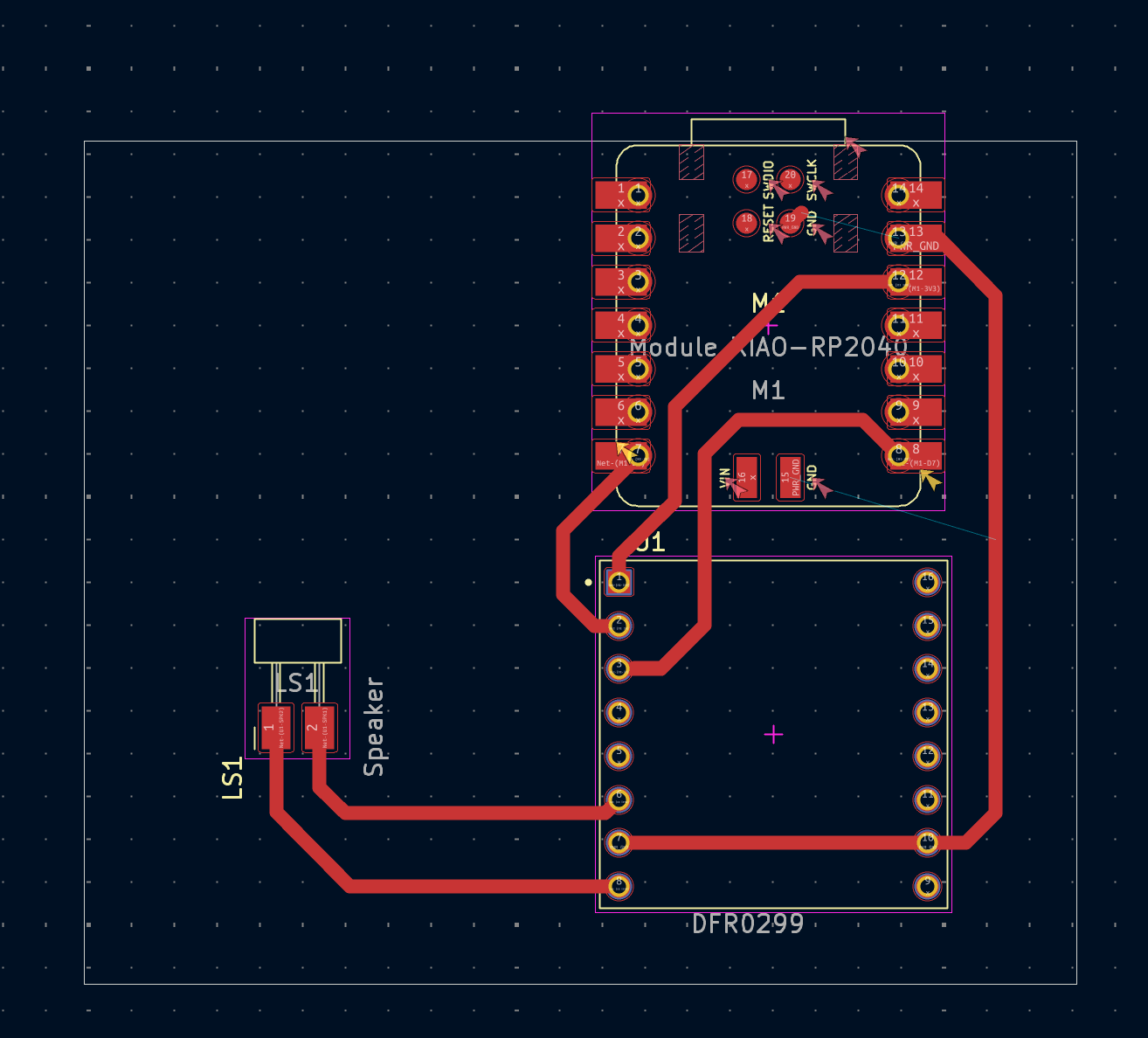
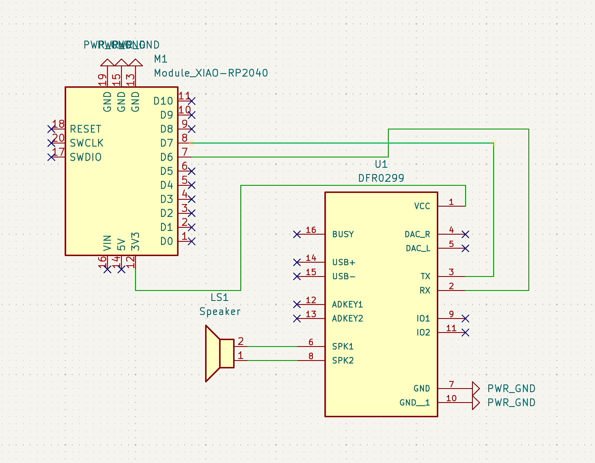
A custom PCB was milled for the speaker/amplifier subsystem using the Othermill machine. The PCB interfaces the audio output with the phone holder amplifier system.
- Design: Circuit schematic and layout for audio routing
- Fabrication: Milled using 1/64" end mill for traces, 1/32" for drilling
- Components: Audio connectors, signal routing, interface connections
Vinyl Cutting
Custom vinyl stickers were designed and applied to the machine for visual identity and subsystem labeling. Designs included "Swiper No Swiping" and "Brainrot9000" logos, processed through VDraw.ai for optimal vinyl cutting.
07 · Integration & Assembly
Subsystem Integration
The complete machine assembly involved integrating all subsystems into a cohesive system:
- Head subsystem: Camera, display, and control electronics
- Phone interaction: Tapper, swiper, and phone holder mechanisms
- Base chassis: Drive system and structural platform
- Body shell: Outer enclosure with door mechanism
- Control systems: ESP32-S3 microcontrollers for coordination
Full System Operation
The complete BrainrotBot system demonstrates:
- Real-time person tracking and following
- Automated phone interaction (tapping, swiping)
- Wi-Fi livestreaming for remote monitoring
- Synchronized motion control across subsystems
- Edge AI inference for autonomous behavior
08 · Key Learnings
- Understanding mechanism design, force transmission, and motion constraints
- Importance of precise CAD modeling and fabrication for functional systems
- Iterative testing and refinement for optimal mechanical performance
- Modular design approach enabling parallel development and integration
- Coordinating multiple mechanical and electronic subsystems
- Establishing clear interfaces between subsystems
- Timing and synchronization of automated actions
- Power distribution and cable management
09 · Conclusion
The Mechanical & Machine Design assignment provided valuable experience in collaborative machine building, integrating mechanical design principles with actuation systems, automation, and user interfaces. The BrainrotBot project demonstrated how modular subsystem design enables complex machines to be built through coordinated team effort.
Key achievements include successful integration of Edge AI for autonomous behavior, precise servo control for phone interaction, and real-time camera streaming for remote monitoring. The project highlighted the importance of clear subsystem interfaces, iterative testing, and coordinated assembly in building functional automated machines.