Week 4
3D Scanning & Printing
09/24/2025 – 10/01/2025
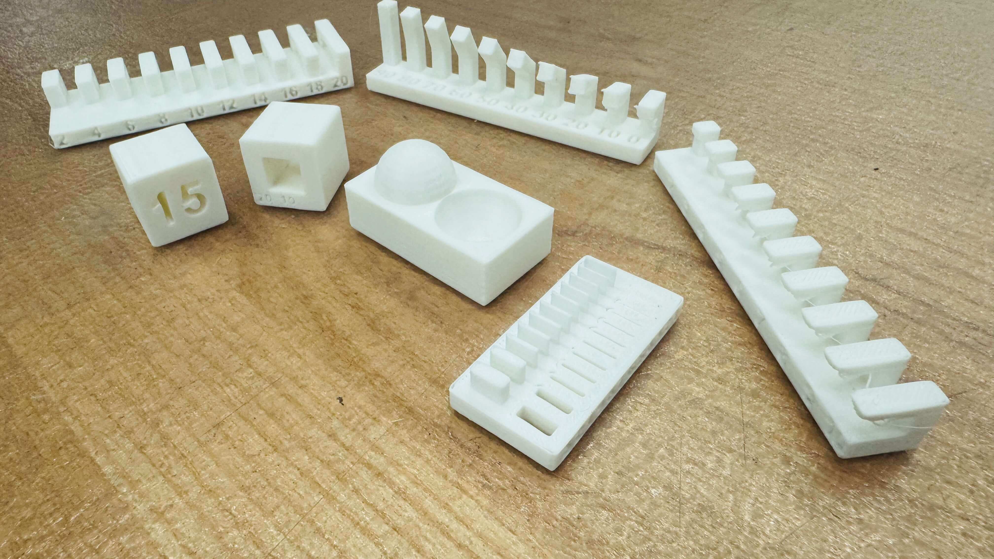
Group Assignment: Test the design rules for your 3D printer(s)
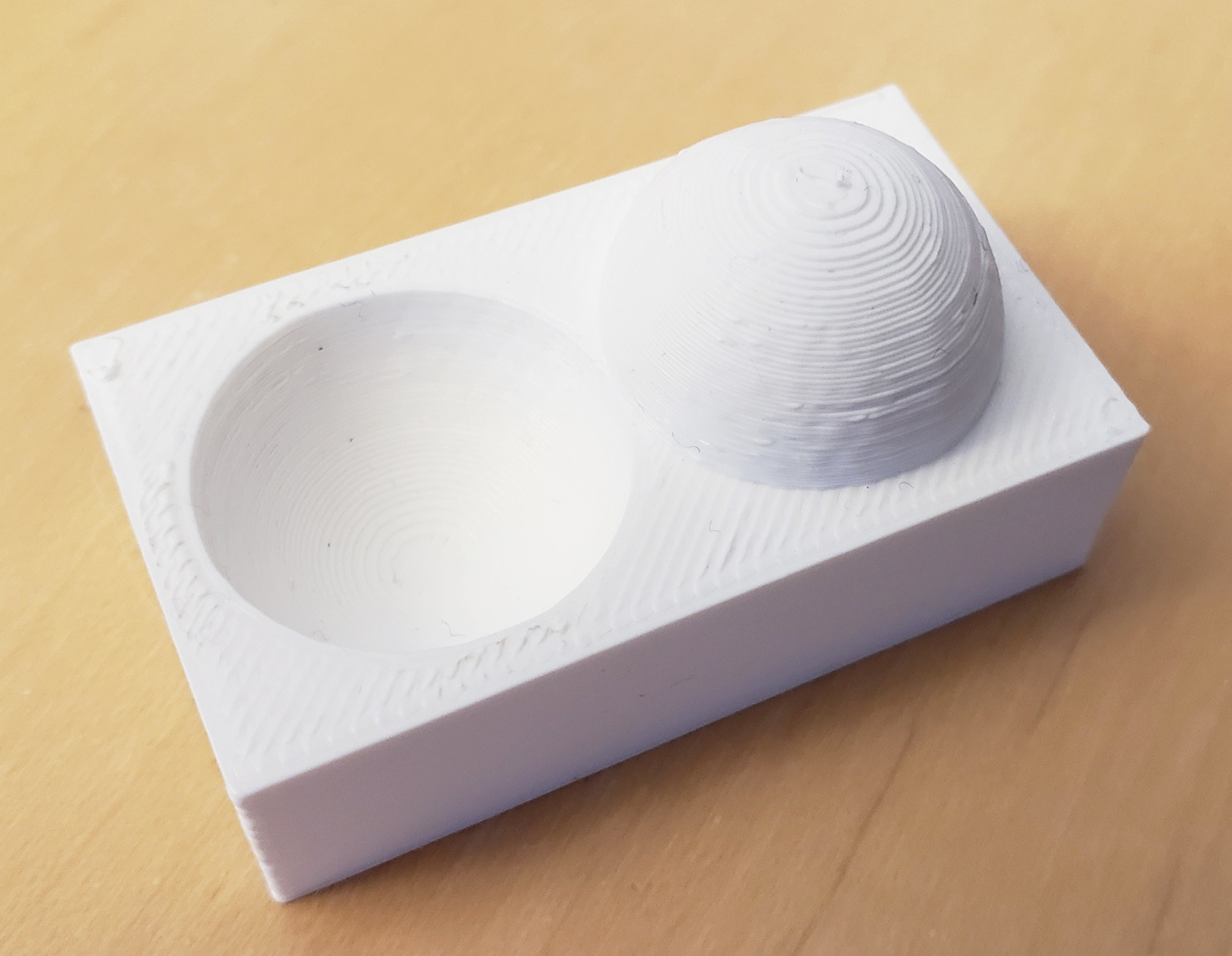
1. Supports: Overhang, Clearance
In 3D printing, overhangs occur when part of the geometry extends outward without material beneath it. Most printers can handle slight overhangs (≈45° from vertical), but steeper angles typically require support structures. Designers should minimize overhangs or integrate self-supporting features like chamfers. Clearance is equally critical: when designing moving parts or interlocking components, a small gap must be included between surfaces so they don't fuse during printing. The exact clearance depends on printer resolution and material but often ranges from 0.2–0.5 mm for FDM printers. Without this, parts that are meant to slide, rotate, or separate after printing may remain locked. Good support and clearance planning ensures parts are both printable and functional without excessive post-processing.
1.1 Supported Overhangs
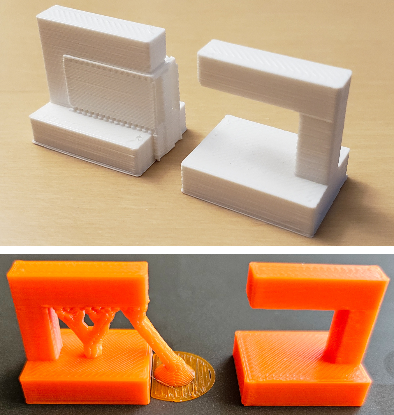
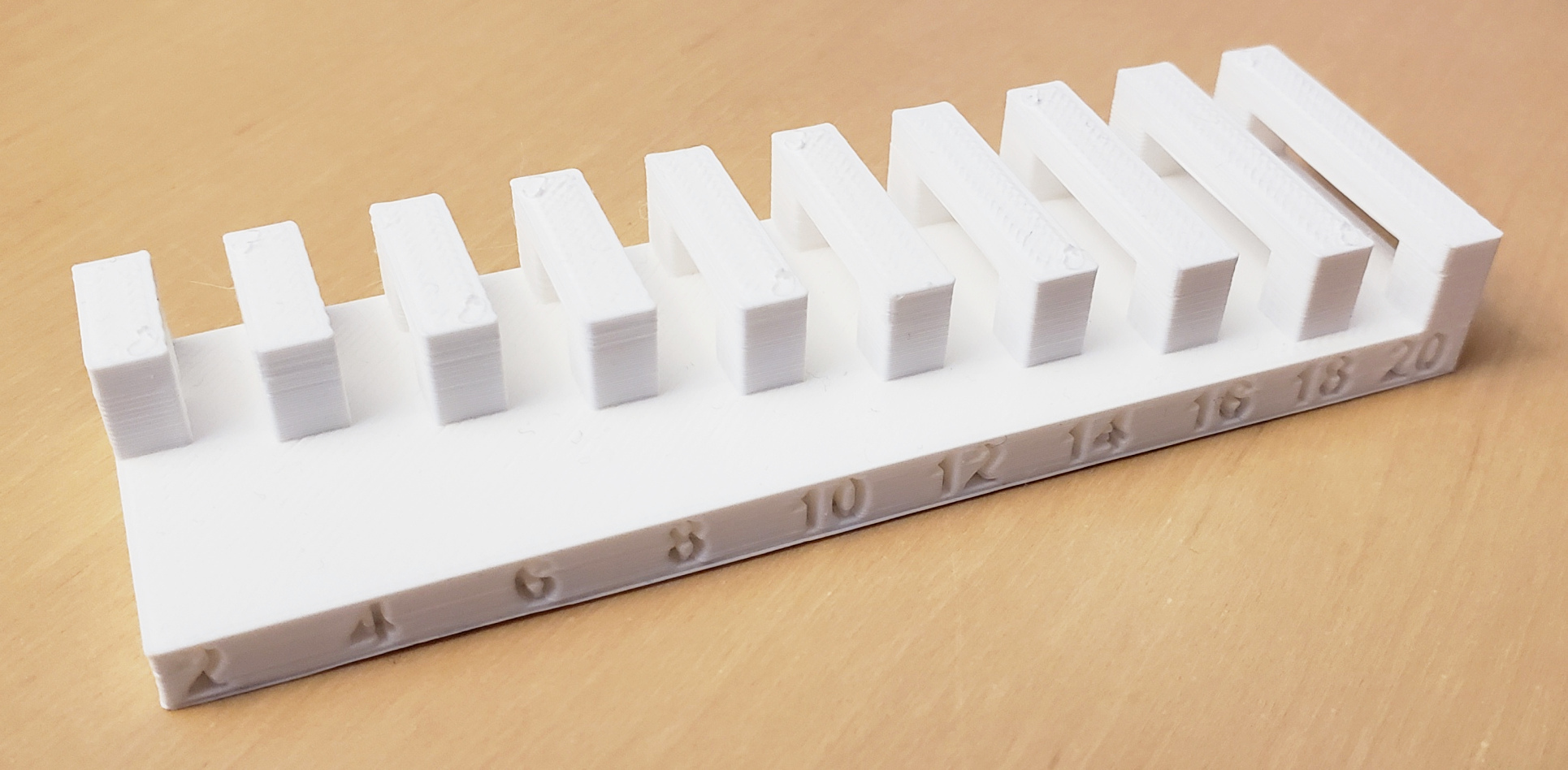
1.2 Supported Clearance

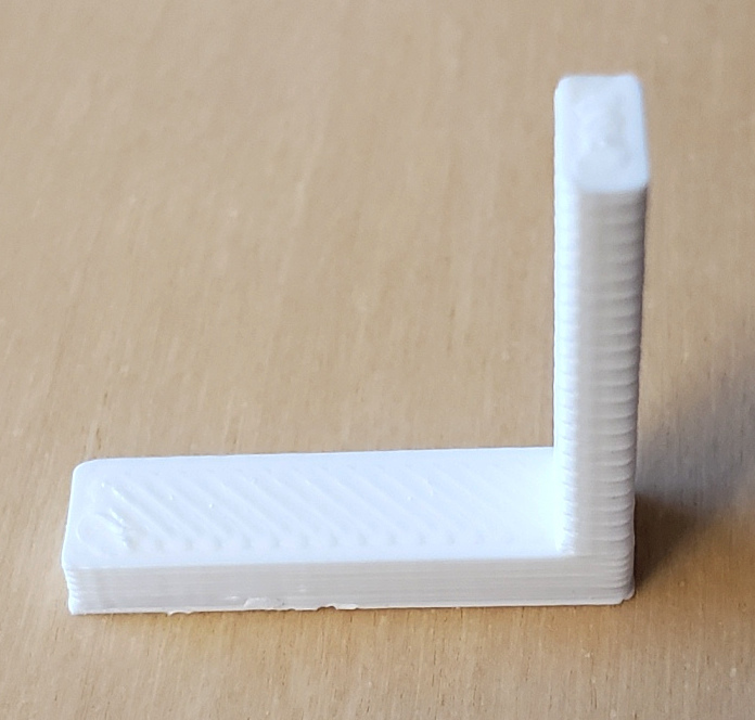
2. Unsupported: Angle, Overhang, Bridging
Unsupported geometries are those printed without scaffolding. Angles are a primary constraint: FDM printers typically handle up to ~45° without sagging. Beyond that, the plastic droops and distorts unless supports are used. Overhang length also matters: short overhangs (a few millimeters) can print fine, but long protrusions almost always need support. Bridging refers to spanning material between two points without support underneath. Printers can bridge small gaps (≈5–10 mm for FDM) if cooling and speed are tuned well, but longer spans sag or break. Designers can minimize unsupported features by breaking models into assemblies, orienting parts differently, or redesigning geometry to reduce bridges. Testing the printer's angle and bridge limits is a common calibration exercise.
2.1 Unsupported Angle
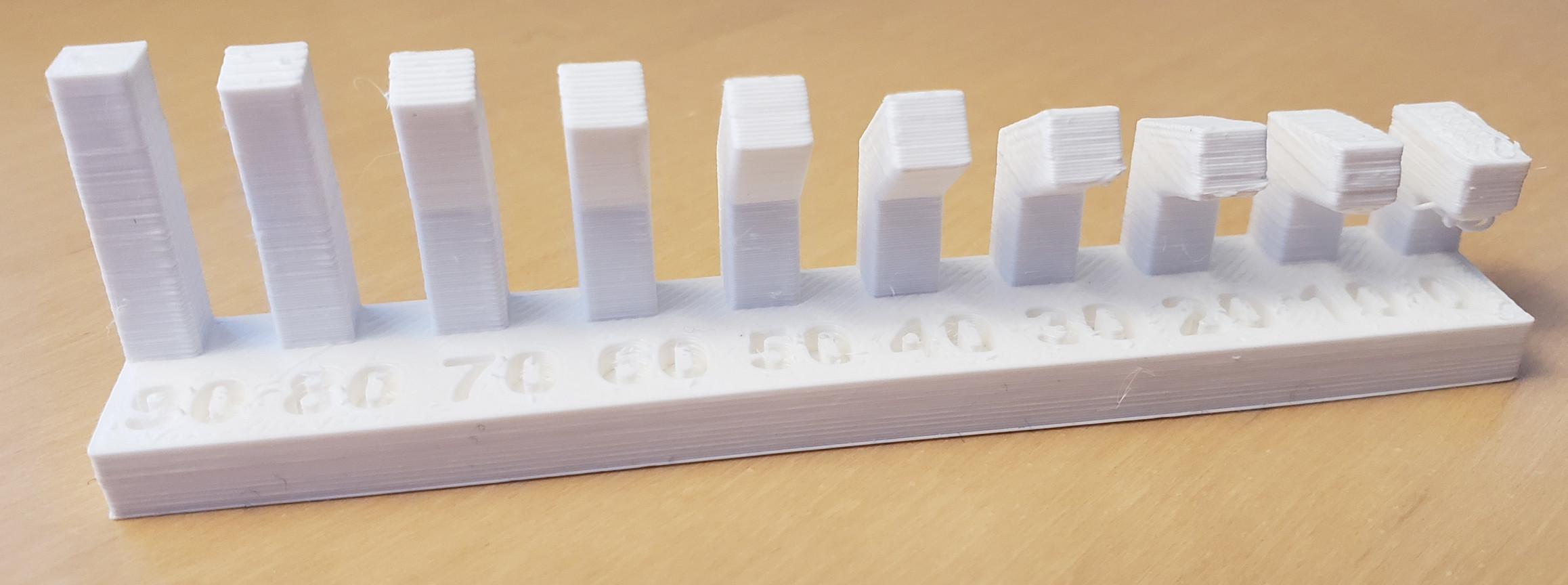
2.2 Unsupported Overhang
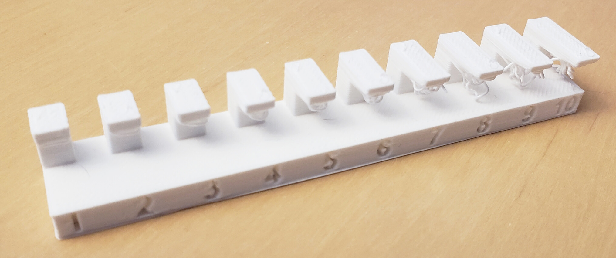
2.3 Unsupported Bridging
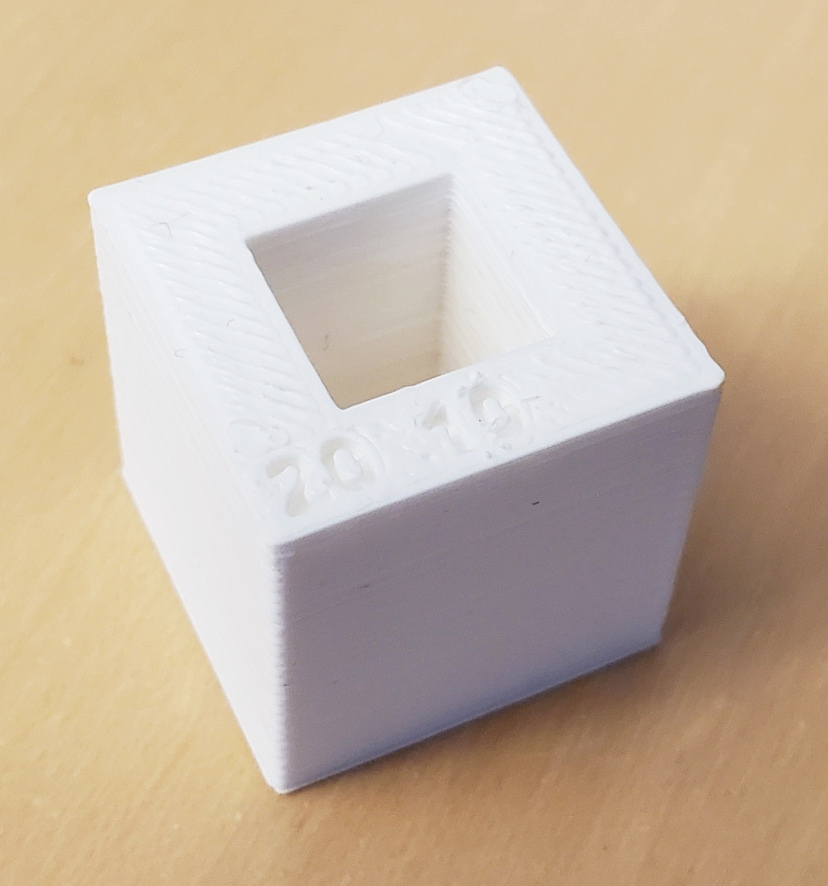
3. Wall Thickness
Wall thickness determines both the strength and the printability of a design. If walls are too thin, they may not print at all (the slicer might ignore them) or will be fragile and prone to breaking. A safe rule of thumb is to make walls at least 2–3 times the nozzle diameter for FDM printers (≈0.8–1.2 mm with a 0.4 mm nozzle). For SLA or SLS processes, the minimum can be thinner but is still governed by material strength and printer specs. Thick walls add rigidity but also increase print time and material use. Uneven wall thicknesses can lead to warping or stress concentration. Therefore, designers should keep walls uniform, ensure minimum values are respected, and adjust for the chosen printing technology.

4. Dimensions
Dimensional accuracy is affected by the resolution of the printer and material shrinkage. Most FDM printers achieve ±0.2–0.5 mm tolerances, while SLA/SLS are more precise. When designing parts that must fit together, allowances must be added — typically 0.2–0.5 mm clearance for press fits and more for sliding fits. Shrinkage is especially relevant in SLS, where nylon powder contracts as it cools. Large flat surfaces are prone to warping, so fillets or ribs may be needed to stabilize geometry. Designers should also avoid very small features that fall below the printer's minimum feature size (nozzle diameter or laser spot size). Prototyping and test prints are often required to dial in the correct offsets for functional assemblies.
5. Anisotropy and Orientation
3D printing creates anisotropic parts — mechanical properties differ depending on orientation. Layers bond strongly within a plane but weakly between planes, making parts weaker in the Z-direction. For load-bearing designs, orientation is critical: aligning stresses along the XY plane increases strength, while printing tall vertical load paths makes them prone to delamination. Orientation also affects surface quality, support requirements, and print time. A part printed flat may be stronger and smoother but require more supports, while standing it upright might reduce supports but increase anisotropic weakness. Designers must balance strength, accuracy, and finish when choosing orientation. Understanding anisotropy is especially important for functional parts that will endure stress or wear.
6. Surface Finish
Surface finish in 3D printing is influenced by layer height, orientation, and post-processing. Layer lines are inherent: smaller layer heights improve smoothness but increase print time. Vertical surfaces aligned with the Z-axis are smoother, while sloped or curved surfaces show a "stair-stepping" effect. Support removal also affects finish: areas contacting supports often require sanding or smoothing. Material choice matters — SLA provides smoother finishes than FDM, while SLS has a slightly rough, powdery texture. To achieve high-quality finishes, designers should orient critical surfaces upward and avoid unnecessary supports. Post-processing techniques like sanding, acetone vapor smoothing (for ABS), or resin coating can significantly improve the finish. The trade-off is between time, material, and desired appearance/function.
Individual Assignment: 3D scan an object (and optionally print it)
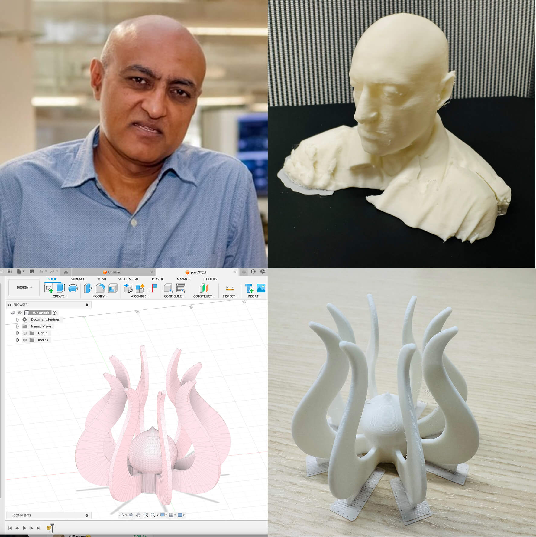
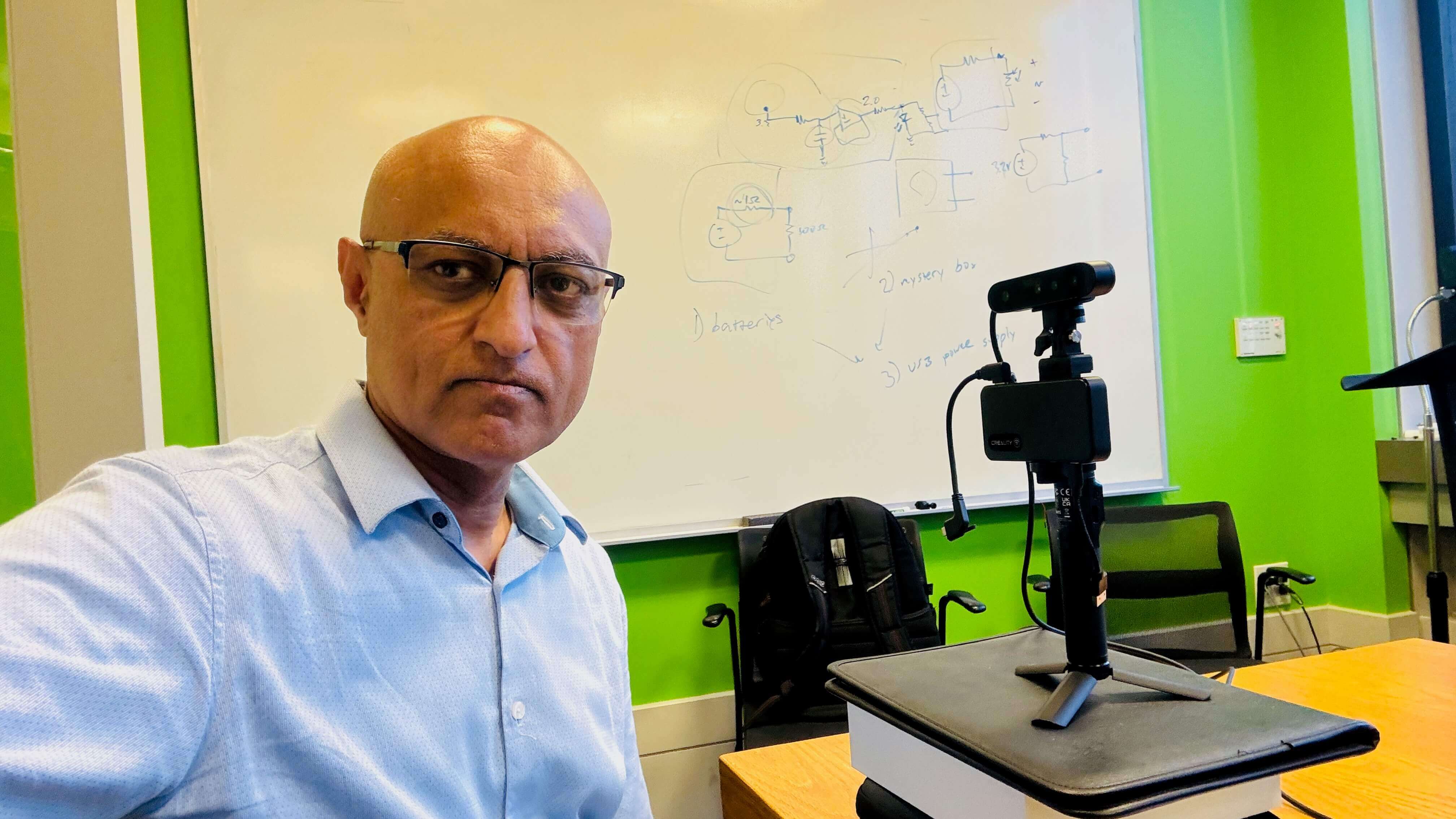
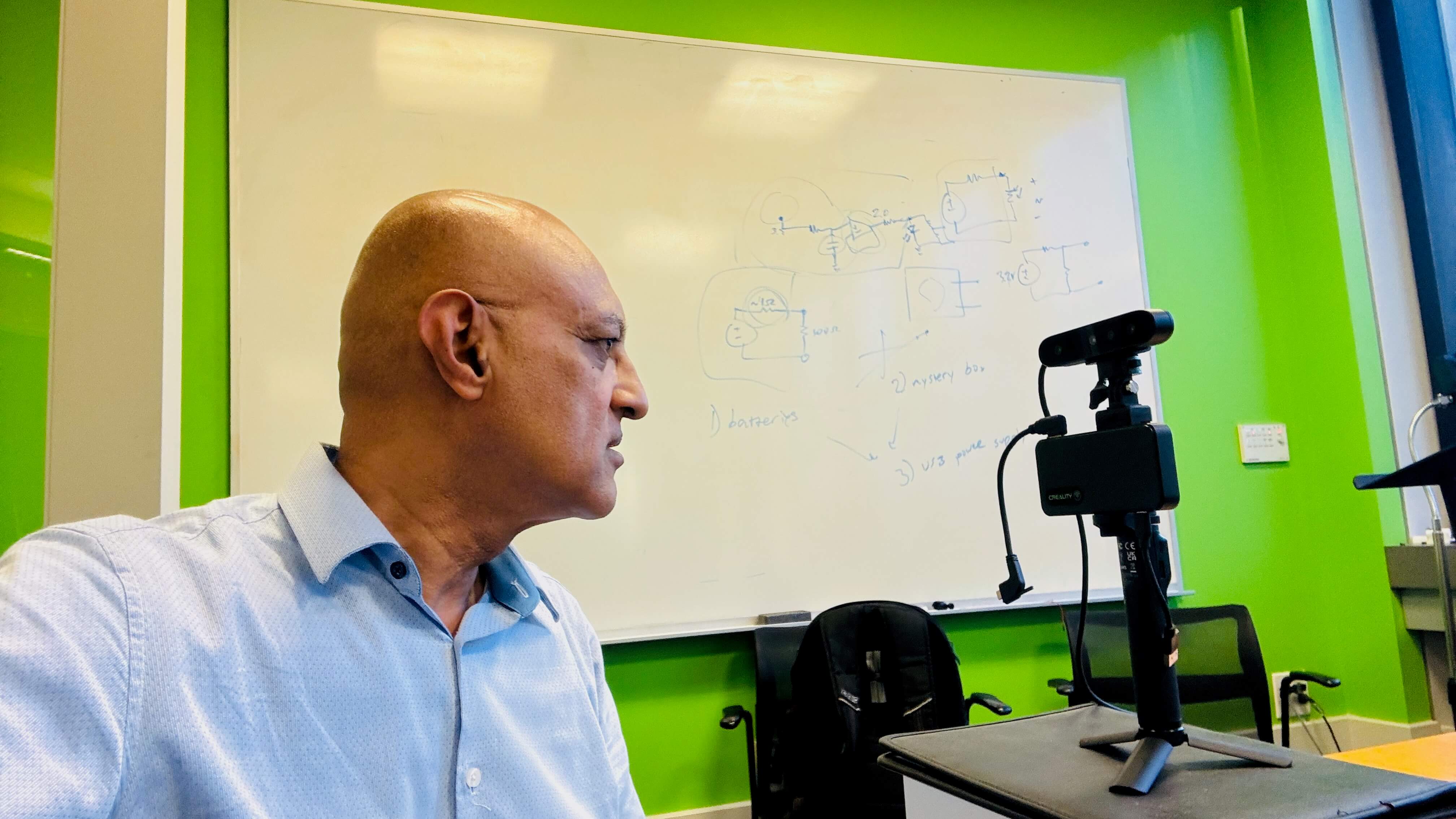
Scanning Process
- Scanner Placement: Placing the scanner on the table edge keeps it stable, which is crucial since handheld scanning often introduces wobble. A fixed scanner + rotating object usually yields cleaner geometry.
- Distance & Framing: Adjusting the distance so your head fills most of the scanning frame helps maximize detail while avoiding clipping. The Ferret likes ~150–700 mm working distance, so upright posture and correct spacing ensure data capture.
- Rotation Method: Using a swivel chair gives a smoother, constant relative rotation — much like rotating an object on a lazy susan. Constant speed is important: moving too fast can cause holes or misalignment, while too slow may capture redundant frames.
- Challenges: Hair, ears, and under-chin regions are tricky for scanners, so you may notice patchy data there. Good ambient lighting (but no glare) helps.
- Post-processing: After scanning
- Fill holes (especially top of head, under chin). The top of the head was covered by bending my head while scanning. The chin did not get scanned/filled, there was a gaping hole in the model
- I used the head AI test tool to fill the holes in my chin and chest.
- Export to OBJ for printing.

3D Printing of my head
The scan data from the Creality CR-Scan Ferret was exported as a .OBJ file and imported into PrusaSlicer. Since my chest was not evenly sitting on the printer bed, I had to push the model down so it rested on the plate below. I used a Prusa Core One 3D printer with PLA white filament, choosing a layer height of 0.20 mm to balance detail and print time. The slicer recommended 15% supports, particularly under the nose and chin areas, where overhangs would otherwise sag — never considered my nose droopy until the 3D printer complained!
The slicer estimated a print time of about three and a half hours. During slicing, I could visualize the support structures in green, which confirmed coverage for critical overhangs. Once printed, the model required some support removal and light cleanup, especially around the shoulders. The final bust captured facial features and contours well, with visible layer lines but good overall fidelity. This workflow demonstrated the end-to-end process from structured-light scanning to slicing and successful FDM printing of a personalized 3D object.
3D print an object that could not be made subtractively
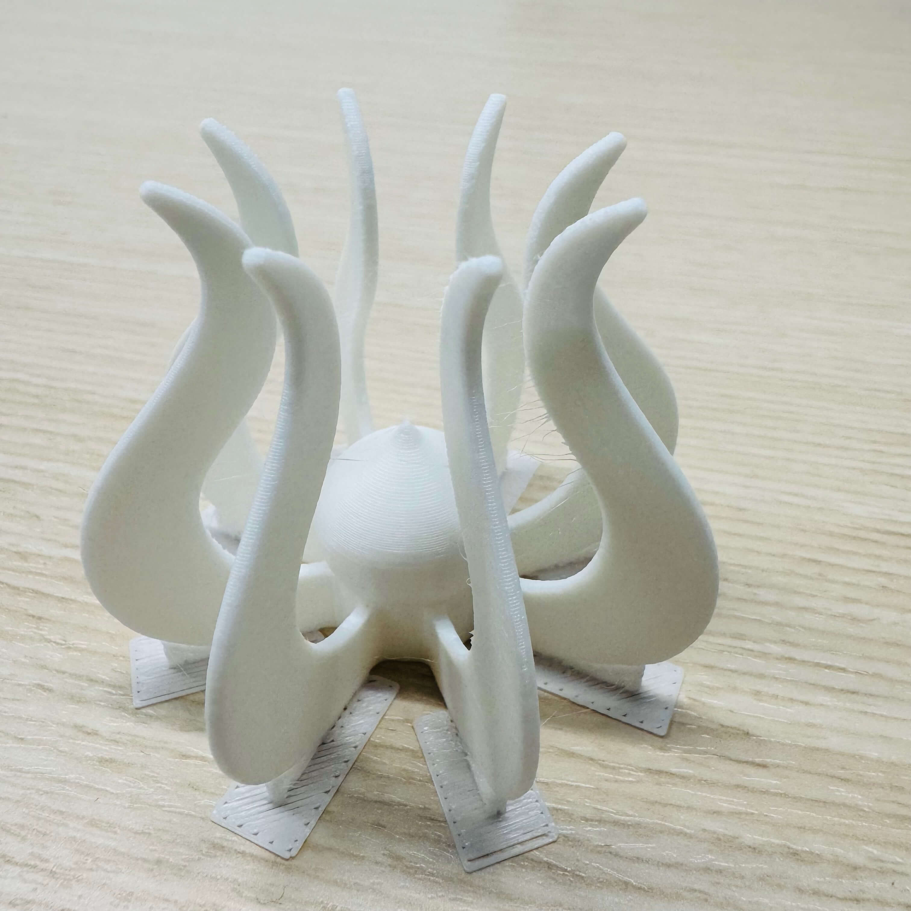
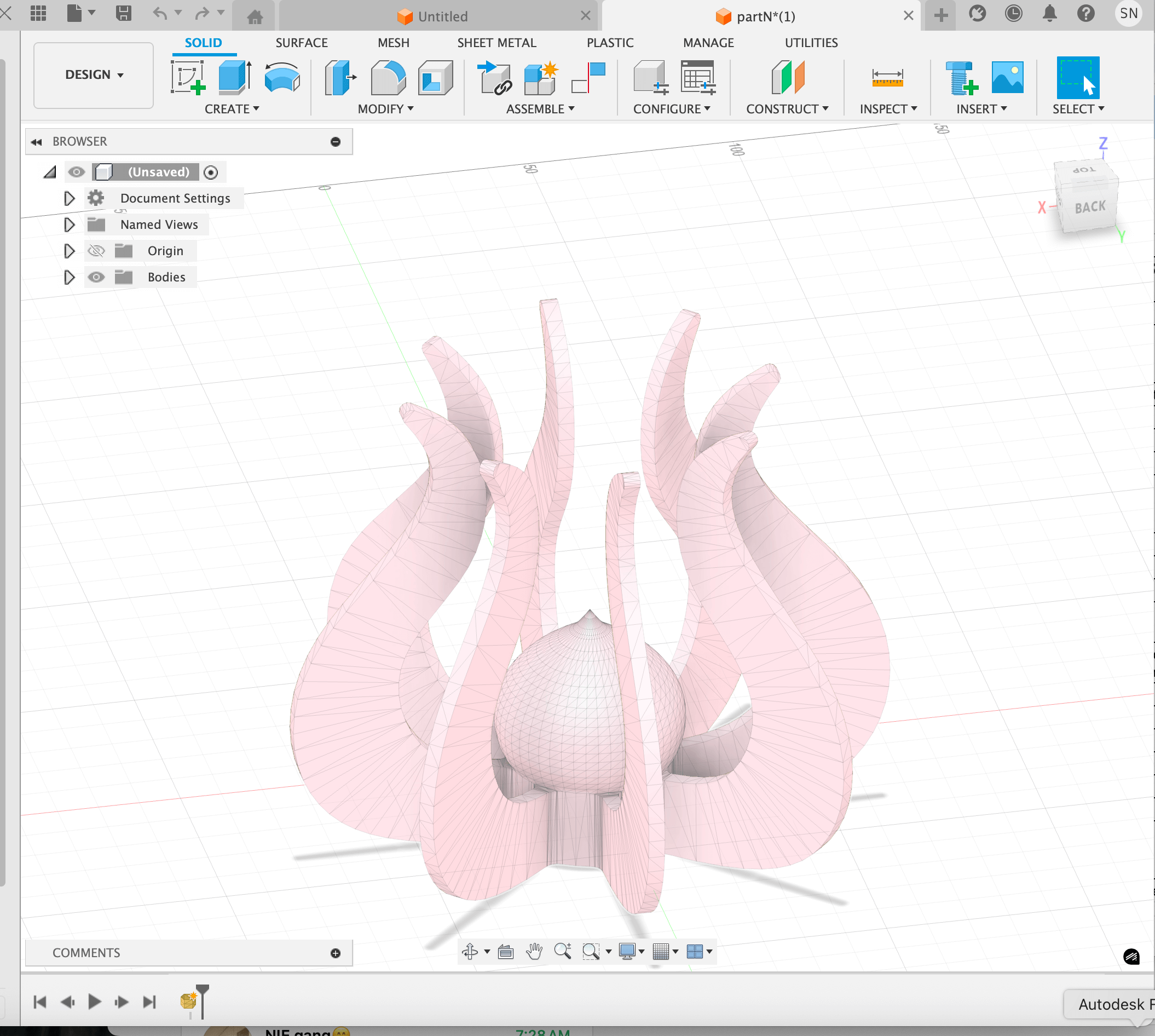
In the Indian cultural context, the lotus symbolizes purity, growth through challenges, and the unfolding of knowledge, making it a powerful metaphor for learning — how to make (almost) anything. I designed a lotus by drawing a single petal shape (using cubic splines), extruded to 3 mm thickness, and patterned it circularly. The bud in the middle surrounded by the petals exemplifies a form best produced additively.
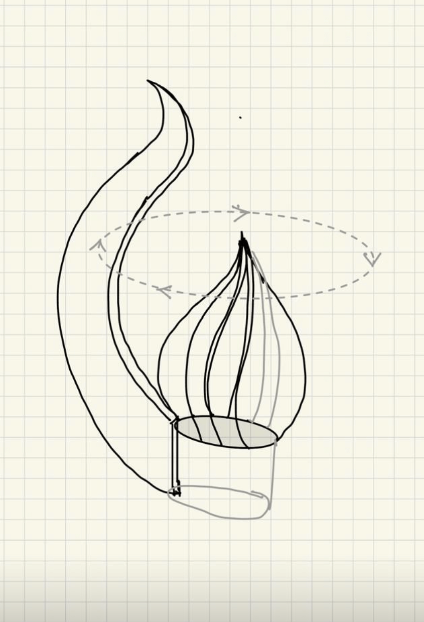
Drew this in AutoCAD Fusion. Start by creating the central bud: sketch a curved profile of a petal on a vertical plane and revolve around the central axis to form a smooth closed bud. Then create the tall outer form by sketching a long spline that curves upward and outward from the base, and use loft or sweep to turn it into a 3D solid. Place both onto a simple cylinder base. Join bodies into a single solid for a clean, printable model.
Sliced the lotus on PrusaSlicer.
The Prusa printer printing the Lotus
Finally we have the white lotus!!