Overview
Output devices are how embedded systems communicate with the physical world and with us. They transform digital signals into light, sound, motion, or heat — making our designs visible, audible, and tangible. This week focuses on understanding different output modalities and implementing them in real hardware. From simple LEDs to speakers, motors, and displays, output devices give our projects a voice, a face, and the ability to act.
This week's assignment explores speakers, amplifiers, and audio output as part of the broader output devices curriculum, which also covers LEDs, displays, motors, and more.
For my assignment, I chose to implement audio output using a digital I²S amplifier as part of my final project, the SmartPi Agentic Assistant. While the initial design focused solely on visual feedback through a 64×64 LED matrix, adding voice capability transforms the device into a truly multi-modal assistant — one that can speak reminders, read notifications, and provide audio alerts without requiring the user to look at a screen.
Assignment: Audio Output for SmartPi Assistant
Context: Enhancing the SmartPi with Voice
The SmartPi Agentic Assistant is a desktop device built on the Raspberry Pi Pico W that uses large language models (LLMs) to process calendar events, emails, and weather data, displaying actionable summaries on an LED matrix. While visual output works well when you're looking at the device, there are many scenarios where audio feedback is more practical:
- Hands-free operation: When cooking, exercising, or working with your hands
- Attention capture: Audio alerts can reach you even when you're not looking at the device
- Accessibility: Voice output makes the system usable without requiring visual attention
- Multi-modal feedback: Combining display and voice creates a richer, more natural interaction
To add this capability, I needed to select an appropriate audio output device that could interface with the Raspberry Pi Pico W and produce clear, intelligible speech without requiring complex external hardware.
Audio Output: Adafruit MAX98357 I²S Amplifier
Why Digital I²S Audio?
The Raspberry Pi Pico W, like most microcontrollers, does not have a built-in digital-to-analog converter (DAC) suitable for audio output. While it's possible to generate analog audio using PWM (pulse-width modulation), this approach produces lower quality sound, requires external filtering, and lacks the fidelity needed for clear speech synthesis. Instead, I chose to implement a fully digital audio path using the I²S (Inter-IC Sound) protocol.
I²S offers several key advantages:
- No external ADC/DAC needed: The Pico sends digital audio samples directly to the amplifier
- Noise immunity: Digital transmission is far less susceptible to electrical interference than analog signals
- Simplified PCB routing: I²S uses standard digital logic levels, avoiding the complexity of analog trace design
- High fidelity: Bit-perfect audio transmission ensures clear, undistorted speech output
- PIO compatibility: The RP2040's Programmable I/O subsystem provides efficient I²S implementation
Component Selection: MAX98357 Class-D Amplifier
The Adafruit MAX98357 is a digital-to-analog Class-D audio amplifier designed specifically for embedded applications. It accepts an I²S digital audio stream and converts it into amplified analog output capable of directly driving a 3–4 Ω speaker at up to 3 watts of power.
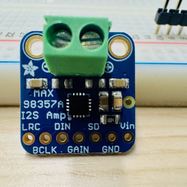
MAX98357 amplifier front view showing the main IC and passive components
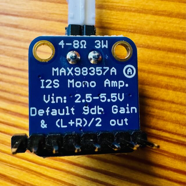
MAX98357 amplifier back view with pin labels for easy connection
Technical Specifications
- Input: Digital I²S audio (BCLK, LRCLK, DIN)
- Output Power: Up to 3.2 W into 4 Ω at 5 V supply
- Supply Voltage: 2.5 V to 5.5 V (5 V recommended for maximum output)
- Efficiency: >85% (Class-D switching amplifier)
- Gain Control: Software-configurable via SD pin
- Sample Rates: Supports 8 kHz to 96 kHz
- Footprint: Compact breakout board (25.4 mm × 17.8 mm)
Why the MAX98357 is Ideal for This Application
The Raspberry Pi Pico W's GPIO pins can only source a few milliamps of current at 3.3 V — barely enough to power an LED, let alone drive a speaker. A typical 4 Ω speaker requires hundreds of milliamps to produce audible sound, and even more for clear speech at comfortable listening levels. The MAX98357 solves this problem elegantly:
- No external amplifier needed: The MAX98357 handles both DAC conversion and amplification in a single chip
- Direct speaker drive: Delivers sufficient current to drive low-impedance speakers without additional stages
- Minimal external components: Only requires power supply decoupling capacitors and speaker connection
- Compact form factor: The Adafruit breakout board fits easily into the SmartPi enclosure
- High efficiency: Class-D amplification minimizes heat dissipation, important for a passively-cooled embedded device
Connecting the MAX98357 to Raspberry Pi Pico W
Purpose and Configuration
Purpose: Converts the Pico's digital I²S audio stream into amplified analog output suitable for driving a speaker directly.
Power: The MAX98357 can operate from 3 V to 5 V. For maximum output power (3 watts), it should be powered from the 5 V rail, which in the SmartPi design comes from the same supply that powers the LED matrix panel. All components share a common ground.
Pin Connections
| MAX98357 Pin | Connect to Pico W | Signal Description |
|---|---|---|
| VIN | 5 V (VBUS) | Power supply input — shared with LED panel power rail (ensure adequate current capacity) |
| GND | GND | Common ground with Pico and all other peripherals |
| DIN | GP18 | I²S Data Input — serial audio data stream from Pico |
| BCLK | GP19 | I²S Bit Clock — synchronizes data transmission |
| LRCLK | GP20 | I²S Left/Right Clock (Word Select) — indicates left or right audio channel |
| GAIN / SD | Tie to 3.3V or control via GPIO | Gain control and shutdown: tie high for always-on operation, or connect to GPIO for software control |
Speaker Connection
Speaker Specifications: Connect a 3–4 Ω speaker to the L+ and L- output terminals on the MAX98357 breakout board. The amplifier produces a differential output, so both terminals must connect to the speaker (do not ground one side).
Physical Implementation
Below is the completed PCB V2 showing the MAX98357 amplifier integrated alongside the Raspberry Pi Pico W, HUB75 LED matrix connector, and digital microphone interface. The amplifier is mounted on header pins for easy replacement and testing.
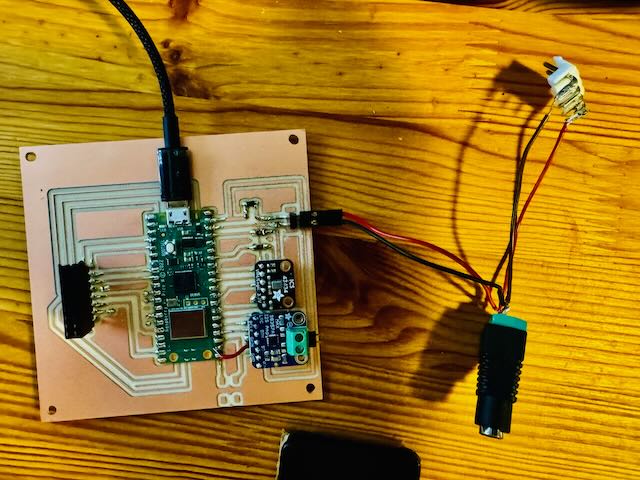
PCB V2 Fully Assembled: All components soldered including Pico W, audio peripherals, and HUB75 interface
Testing the Audio Output
✅ Independent Testing: The MAX98357 and speaker can be tested independently from the rest of the SmartPi system. By loading a simple test program that generates audio tones or speech synthesis, you can verify proper I²S communication and audio output without needing the LED matrix or microphone connected.
Sample Test Code: CircuitPython supports I²S audio output through the audiobusio library. A basic test can play a tone or WAV file to verify the connection:
import board
import audiobusio
import audiocore
import array
import math

# Configure I²S audio output
audio = audiobusio.I2SOut(board.GP19, board.GP20, board.GP18)  # BCLK, LRCLK, DIN

# Generate a simple 440 Hz sine wave (A4 note)
sample_rate = 16000
length = sample_rate // 440
sine_wave = array.array("H", [0] * length)
for i in range(length):
    sine_wave[i] = int((1 + math.sin(math.pi * 2 * i / length)) * 32767)

sine_wave_sample = audiocore.RawSample(sine_wave, sample_rate=sample_rate)

# Play the tone
audio.play(sine_wave_sample, loop=True)
print("Playing 440 Hz test tone...")
If the speaker produces a clear tone, the I²S connection is working correctly. You can then proceed to implement text-to-speech synthesis or play pre-recorded audio files.
Integration with SmartPi Agentic Assistant
System Architecture
In the complete SmartPi system, the MAX98357 amplifier enables the device to vocalize LLM-generated summaries and alerts. The workflow is as follows:
- Data Aggregation: The n8n workflow collects data from calendar, email, and weather APIs
- LLM Processing: An LLM summarizes the information into concise, actionable text
- Multi-modal Output: The summary is sent to the Pico W, which simultaneously:
- Displays the text on the 64×64 LED matrix
- Converts the text to speech and plays it through the MAX98357 amplifier
This dual-mode output makes the SmartPi Assistant accessible in a wider range of situations. You can glance at the display when working at your desk, or hear the alert when you're across the room.
Text-to-Speech Implementation
For speech synthesis, I'm evaluating two approaches:
- Cloud TTS: Send text to a cloud TTS API (e.g., Google Cloud Text-to-Speech, ElevenLabs) and stream the audio back to the Pico W. This produces the highest quality voice output but requires internet connectivity.
- Local TTS: Use a lightweight on-device TTS library like
talkieorpico2waverunning on the MCP bridge server, which then sends PCM audio samples to the Pico. This reduces latency and eliminates cloud dependencies.
Future Enhancements
With the audio output hardware in place, several exciting extensions become possible:
- Alert Tones: Play distinctive notification sounds for different event types (meeting reminder, weather alert, email notification)
- Voice Interaction: Combined with the digital I²S microphone (covered in the Input Devices week), the SmartPi can support conversational interaction
- Music Playback: Stream music or podcasts as a secondary function
- Audio Feedback: Provide confirmation tones when receiving commands via the microphone
Design Considerations and Lessons Learned
Power Supply Design
One critical lesson from this implementation: audio amplifiers can draw significant current. At maximum volume, the MAX98357 can draw over 1 A from the 5 V supply. This must be factored into the overall power budget, especially when the LED matrix is also active (which can draw several amps).
Solution: In PCB V2, I widened the 5 V power traces to 40 mil (from 16 mil in V1) to handle the increased current without excessive voltage drop. I also added bulk capacitance near the MAX98357 to handle transient current demands during audio playback.
Ground Plane and Noise Reduction
Even though I²S is a digital protocol, the speaker output is analog and susceptible to noise. To minimize ground loop interference:
- The MAX98357's ground pin is connected to a solid ground plane shared with the Pico
- Power supply decoupling capacitors (10 µF and 100 nF) are placed as close as possible to the amplifier's VIN pin
- The speaker wires are kept short and twisted to reduce EMI pickup
PCB Layout
In the SmartPi PCB V2 design, the MAX98357 is positioned near the board edge to allow easy access to the speaker connection. The I²S signal traces (GP18, GP19, GP20) are routed with controlled impedance and kept away from high-current traces (LED matrix power) to prevent crosstalk.
This assignment connects to several topics from the Output Devices class page:
- Speaker: I²S MAX98357A amplifier implementation
- Power: Understanding current requirements and power supply design
- PWM: Alternative to I²S for simpler (but lower quality) audio output
Conclusion
Adding audio output via the MAX98357 I²S amplifier transforms the SmartPi Agentic Assistant from a visual-only display into a truly multi-modal ambient intelligence device. The choice of digital I²S audio over analog PWM ensures high fidelity and noise immunity, while the Class-D amplification provides efficient power delivery in a compact form factor.
This implementation demonstrates the power of output devices in embedded systems: by adding just one component, we've fundamentally changed how users can interact with the device, making it accessible in hands-free, eyes-free scenarios. The modular design also sets the foundation for future enhancements, including voice interaction and conversational AI capabilities.
Next Steps: In the Input Devices week, I'll add a digital I²S MEMS microphone to enable voice input, completing the bidirectional audio capability and allowing the SmartPi to transition from a push-only notification device to a fully interactive voice assistant.