
Intro - Building a (childhood) dream
For my HTM(A)A final project, I decided to finally chase a dream I’ve had since I was little: build a real robot, like the BattleBots I watched on TV as a kid. (Yes, the kind of childhood dream that usually stays safely in the “maybe one day” drawer.)
So here’s the plan: design, prototype, manufacture, and assemble a small-scale combat robot - all by myself. And if I get the chance, I’ll even let it fight in an arena. 🤖🔥
I’m doing this for two reasons:
- Learn the essentials: mechanical design, electronics, weapon systems, and all the tradeoffs that make a robot both competitive and impossible to break without crying.
- Prove a point: that the only thing between my childhood self and reality is actually doing the work.
⚠️ Note before you continue reading ⚠️
This page works as my project diary, but keep in mind: I early on discovered that robot design is not a clean, linear journey. Each “week” I’ll try to do something different - so, essentially each “week” is really a topic, not a strict timestamp. So I’ll jump back and update older sections whenever a new discovery forces a redesign.
You’ll notice this because I use version numbers for every meaningful update of the robot. However, not every update is relevant for every topic. So if you see numbers skip around… don’t panic. It usually means progress, or occasionally a design mistake I prefer to ✨ mysteriously ignore ✨.
Week 1 - Entering the world of (tiny) robots
Where to start?
Combat robotics is no joke. If I want my robot to actually compete and not retire after three seconds, I need to understand the tradeoffs behind every design choice. My childhood BattleBots memories are not enough, so the first step is simple: learn the field.
Last year I saw a flyer for the MIT Combat Robotics Club (CRC). Perfect starting point. I reached out and began attending CRC meetings to learn from people who build and compete regularly. This was extremely helpful for practical advice like what chassis designs survive, what usually breaks first, and which parts are easy to source vs which parts make you question your life choices.
The club meets on Saturday afternoons. I really like robots, but I can already predict that my attendance will be... flexible. Still counts as research.
In parallel, I did what any modern beginner does: I fell into the online rabbit hole. I read blogs, watched YouTube videos, and even found a WikiHow page that explains how to build an antweight robot. Simple, approachable, and surprisingly useful.
Below are the resources I used:
- https://www.wikihow.com/Build-an-Antweight-Combat-Robot
- https://www.youtube.com/watch?v=uQZUa15e-mk
- https://www.youtube.com/watch?v=Ob6LiUoSAFI
- Adventures in Science: Plastic Ant Combat Bots Chassis Design Tips
Rules
Combat robotics is built around three judging criteria. These decide who wins when both robots are still alive at the end.
- Damage 💥: How much you actually harm or disable the opponent. The more parts you remove, the better.
- Control 🎮: How well you dominate the fight. This includes pinning, pushing, steering the opponent, and deciding where the action happens.
- Aggression ⚡: How actively you engage. You need to attack, not run laps around the arena. (Tempting, sometimes.)
A bot can win by knockout if the opponent becomes immobilized. Otherwise, judges use the three criteria above to score the match.
Other important rules every builder should know:
- Weight classes define the maximum mass of a robot. Antweight up to 1 lb, beetleweight up to 3 lb, then 12 lb, 30 lb, and more.
- Weight multipliers reward creative mobility systems like walkers or shufflers. They often get up to about 50 percent more weight to balance the engineering challenge.
- Active weapons are required in most competitions. A robot cannot just be a wedge with good intentions.
- Safety systems include kill switches, a removable link, and protection for sharp edges when out of the arena.
- Weapon restrictions usually ban projectiles, fluids, nets, glue, and sometimes fire. Controlled destruction is allowed.
- Repair windows give teams around 15 to 30 minutes to fix their bot between matches.
Week 2 - What makes a (good) battlebot
Connecting with the MIT Combat Robotics Club was the best decision I could have made at this stage. The CRC members are incredibly knowledgeable and generous with their time. Ryan, Tom, Carlos, and the rest of the team: you are genuinely impressive, and I learned a lot from you.
Below is everything I gathered this week.
Robot Categories
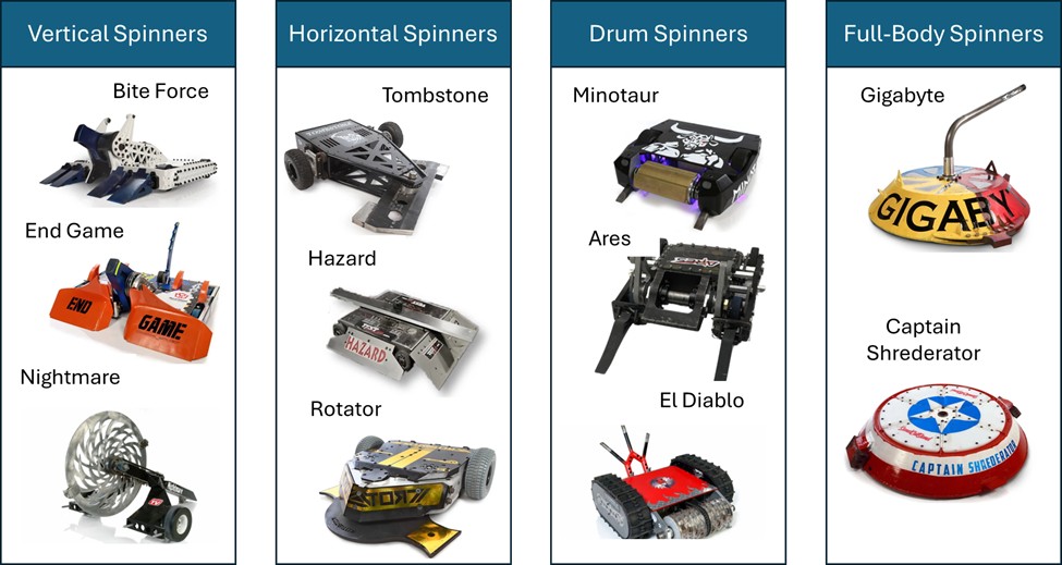
Combat robots usually fall into two big families: spinners and non-spinners. Each category comes with design trade-offs, strategic considerations, and build difficulty level (in brackets below).
Spinner categories:
- Horizontal spinners (Intermediate): High rotational inertia and large striking surface, great for delivering strong hits. However, they are energy-hungry and can be self-destructive if the frame or bearings aren’t robust. Gyroscopic forces don’t affect driving.
- Vertical spinners (Intermediate): Very popular in competitions because they can flip opponents, throw them into the air, and concentrate energy into a smaller contact area. Downsides: destabilizing recoil and high stress on weapon mounts.
- Drum spinners (Intermediate): Cylindrical weapons spinning at high RPMs. They offer a balance of energy and control: easier to armor, often smaller bots use them. Weakness: less reach than horizontal or vertical spinners.
- Shell or full-body spinners (Complex): The entire outer body spins, turning the whole robot into a weapon. Devastating when they connect, but they are hard to control, slower to spin up, and very vulnerable if they get flipped. Ring spinners (Complex) are a rare variation where an external ring spins around the robot’s frame. They can deliver powerful hits but are difficult to build and maintain.
Non-spinner categories:
- Wedges / rammers (Simple): Simple, reliable, and effective. Designed to get under opponents and push them around. Win by control and durability, not by damage.
- Lifters (Simple): Use mechanical arms or actuators to lift opponents. Effective against low-ground bots but require precise geometry and torque.
- Flippers (Simple): Powered by pneumatics or strong actuators to flip opponents. Spectacular in matches but need careful timing and a solid power system.
- Clamps / grabbers (Simple): Use jaws or arms to immobilize opponents. Effective in control fights but usually less dramatic; demand robust servos and torque.
- Flamethrowers (Complex): very cool but often only effective only in lower weight classes, as in higher weight classes few exposed parts are made out of plastic materials.
- Hybrids (Varies but generally complex): Combine one of the above with a spinner or secondary weapon (e.g., lifter + horizontal bar). Hybrids are versatile but often compromise on weight and reliability.
Key lessons & rules of thumb
- In Combat Robotics, impact is king: you don’t actually get much time in direct, controlled contact with another robot (and often you don’t want to). This means that while many designs look cool on paper, they often end up ineffective in practice unless they can consistently deliver powerful, fight-ending impacts.
- Durability > peak power: many matches are won by robots that keep operating under repeated impacts. Redundancy, robust fasteners, sensible armor, and easy field repairability are often more valuable than absolute weapon power.
- Weight class constraints force tradeoffs: armor, weapon mass, battery capacity, and motor choices must be balanced. If you add heavier armor you lose weapon or battery capacity, etc.
- Build around components: Key parts (like motors, ESCs, batteries, and wheels) will shape the entire design. Choosing them early and designing the chassis and weapon systems around those constraints leads to a more reliable and realistic build.
- Driver & control matter: mechanical design is important, but driver skills are equally required.
- Start small / iterate quickly: build a simple prototype early to learn wiring, mounting, and driving. Then improve from there.
- Modularity pays: design your chassis so weapons, batteries, and electronics are accessible and replaceable after hits.
Choosing my bot
After comparing different weapon types, I chose to build a horizontal spinner. The reasoning is straightforward: it gives a strong mix of destructive power and doable engineering. Compared to vertical spinners, horizontals create less recoil, are easier to mount securely, and still deliver serious impact without relying on flipping or clamping systems. They are not the simplest design, but for a first competition-ready robot they strike the right balance of power, reliability, and feasibility.
For size, I picked the antweight class, meaning the robot will stay under 1 lb. Most builders start in the lighter categories and then move up, so this seems like the right path. The budget for an antweight bot is still meaningful, usually 100 to 500 dollars, which makes design choices matter from the very beginning.
Week 3 - Understanding (most) limitations
Key parts
Through research and CRC discussions, I’ve understood the core components that every combat robot needs. These dictate the design (and sourcing strategy):
- Battery
- Drive Motors
- Wheels
- Weapon Motor
- Drive ESC (Electronic Speed Controller): Regulates power between battery and motors;
- Weapon ESC: Regulates power between battery and weapon motor;
- Receiver: Connects the robot to the driver’s transmitter.
- Transmitter: The handheld remote used to drive and activate the weapon.
- Switch
In addition to these main parts, there are many secondary components that must be sourced but don’t drive the overall design as much: standoffs, spacers, mounts, fasteners, screws, etc. These are important for assembly, stability, and repairability, but they can usually be adjusted later in the process without forcing a redesign.
Timeline
Let’s try to commit to this timeline, so as to have a bot ready by mid December.
- CAD completed by end-October: first CAD design built around components and constraints
- Prototyping through November: testing chassis, weapon mount, and drive system. Adjust CAD as needed.
- Manufacturing and assembly by late November and December: ensuring the bot is battle-ready by end of the semester.
Week 4 - Sourcing the (apparently) right components
It quickly became clear that I needed to design the robot around its components. Choosing parts is not simple. Every item has to balance performance, weight, durability, and price, which is a mix that can get tricky fast.
After reading through combat robotics forums and talking with the CRC team, these components seem to offer the best tradeoff for my build. To CAD, I will mostly need the Weapon Motor and the Drive Motors, while the others will come into play later. It’s not best practice, but I will understand later on in the semester what all these components actually do and why I chose them (Future Vittorio Edit: Check Week 10!)
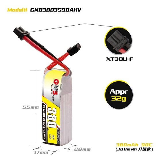
Battery
Gaoneng GNB 380 mAh 3S 11.4 V HV 90C LiPo Battery - XT30 (Pyrodrone)
- Link: https://pyrodrone.com/products/gaoneng-gnb-380mah-3s-11-4v-hv-90c-lipo-battery-xt30?country=US¤cy=USD&gad_campaignid=23149171642&variant=39434416750635
- Price: $11.99
- Weight: 32 g (+/-1 g)
- Specifications:
- Nominal Voltage: 11.4 V
- Dimensions: ~20 × 17 × 55 mm
- Max continuous discharge: 90C
- Max burst discharge: 180C
- Connector: XT30
- Why I chose it: Lightweight yet high-discharge for the antweight class; keeps weight budget low while providing sufficient power.
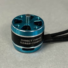
Weapon Motor
Repeat Robotics 2822 Direct Drive Motor V2 (1800 kv)
- Link: https://repeat-robotics.com/buy/2822-direct-drive-v2/
- Price: $20
- Weight: 43 g
- Specifications:
- KV rating: 1800 kv (also available in 1100 kv and 2300 kv)
- Shaft: 4 mm diameter, 20 mm stickout
- Why I chose it: A proven motor for antweight horizontal spinners. The direct drive layout reduces mechanical complexity, and the 1800 kv version offers a good balance between torque and weapon tip speed.
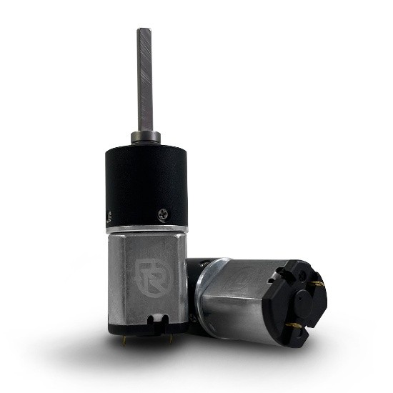
Drive Motors
Repeat Robotics - Mini Brushed MK2 Drive Motor
- Link: https://repeat-robotics.com/buy/brushed/
- Price: $20 (each)
- Weight:
- 27.5 g with 4 mm shaft
- Specifications:
- Motor type: Custom-wound 030 brushed motor
- Voltage range: 2S to 4S rated, recommended voltage: 3S (12 V)
- Gearbox: All-metal planetary, 16 mm, 22.6:1 ratio
- Output shaft: 4 mm D-shaft, extra-long
- Performance:
- At 3S (12 V):
- Free speed: 1220 rpm
- Stall current: 2 A
- Stall torque: 1187 g⋅cm
- Max power: 3.72 W
- At 2S (7.4 V):
- Free speed: 752 rpm
- At 4S (14.8 V):
- Free speed: 1504 rpm
- Why I chose it: A lightweight, proven brushed motor with a strong all-metal gearbox.
Drive ESC
Repeat Robotics - Budget Ant DESC (dual brushed ESC)
- Link: https://repeat-robotics.com/buy/desc/
- Price: $15
- Weight: 7 g including wires
- Specifications:
- Board size: 24 × 18 × 5 mm
- Continuous current: 2 A per channel
- Burst current: 4 A per channel
- Recommended voltage: 2S to 3S LiPo
- Can operate on 4S, but only with caution since stalls can overload the ESC
- Features: dual brushed outputs, optional onboard mixing, center braking, onboard BEC
- Why I chose it: Lightweight, compact, and specifically designed for antweight brushed drive motors. It meets the current requirements, fits well within the weight budget, and keeps wiring simple.
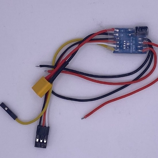
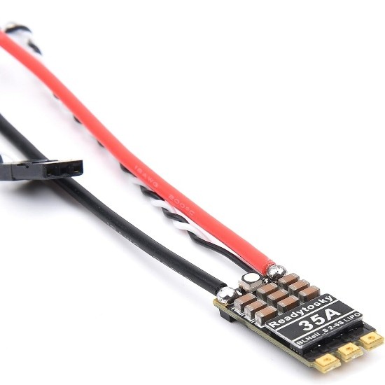
Weapon ESC
Readytosky 35A BLHeli_S Ant Weapon ESC
- Link: https://repeat-robotics.com/buy/readytosky-35a-blheli_s-ant-weapon-esc/
- Price: $13.50
- Weight: 6 g including wires
- Specifications:
- Continuous current capacity: 35 A
- Voltage support: 2-6 S LiPo
- Size: 13 × 29 mm
- Extra features: onboard RGB LED, solder-pad holes for easy motor wiring
- Why I chose it: Lightweight and built specifically for antweight weapon applications.
Receiver
Flysky FS2A Receiver
- Link: https://repeat-robotics.com/buy/flysky-fs2a-receiver/
- Price: US $13
- Weight: 0.9 g (receiver only)
- Specifications:
- Channels: 4CH
- Protocol: AFHDS-2A
- Operating voltage: 3.3 - 10 V
- Size: 11 × 25 mm
- Current draw: ~20 mA
- Range: ~400 + meters
- Why I chose it: Extremely lightweight and compact, ideal for an antweight build. Reliable protocol, minimal footprint, and fits well inside the constrained space of a small robot.
Switch
Fingertech Switch
- Link: https://repeat-robotics.com/buy/fingertech-switch/
- Price: $10
- Weight: 12 g
- Specifications:
- Type: 2-position mechanical switch
- Max current rating: 10 A continuous
- Mounting: 2-hole flange, fits standard antweight layouts
- Why I chose it: Having a reliable switch is key for safety and compliance. This model is lightweight and compact, and it will let me reliably power on/off the bot during pit time without adding bulk or weight.
Others
Two items are still pending in my build: the transmitter and the wheels.
For the transmitter, I decided to choose it later. It does not affect the CAD model or the mechanical design, so I can safely postpone the decision until the bot is physically assembled. Once everything is wired and tested, I will select a transmitter that is compatible with my Flysky FS2A receiver.
For the wheels, my plan is to 3D print them. Printing gives me more control over size, tread, and weight, and it keeps the total cost low. Note: Later in the process, I realized that I needed a proper way to mount the wheels reliably to the drive motors. That led me to buy a screw hub, which provides a solid mechanical interface (https://repeat-robotics.com/buy/brushed/)
Week 5 - From idea to CAD (barely)
Order of operations
My bot can be split into modules: chassis module (it includes top and bottom plates, walls, etc), weapon module (weapon design and mount), and drive module (wheels and how to keep them in place). This week I’ll design the chassis plates and walls. Next comes the weapon, then the drive system. After that, I’ll iterate to align everything.
Inspirations
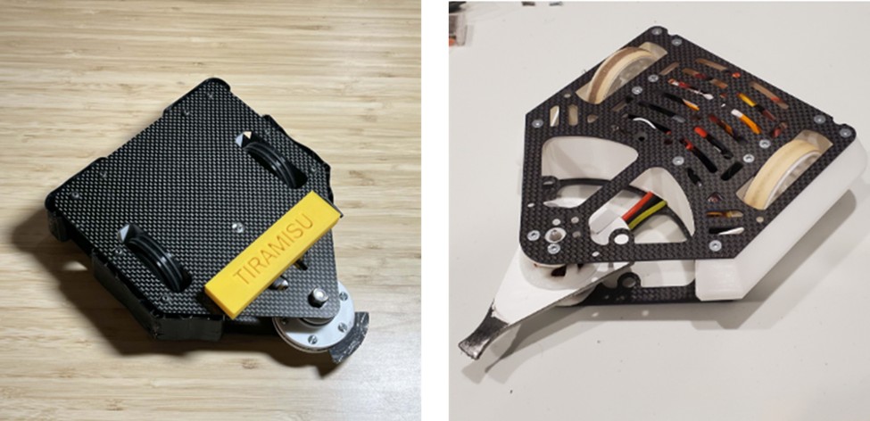
I studied successful antweights like Cheesecake and Tiramisu, both consistently in the top rankings (and both surprisingly with a dessert-related name?!). They have several years of battle footage online, and Cheesecake has a YouTube channel that helped me understand what works and what fails.
Top and bottom plates design
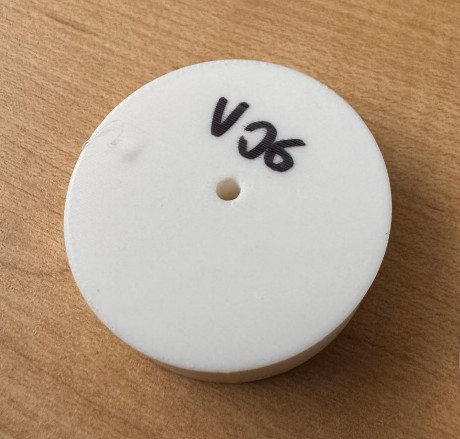
Version 06
Designing the chassis meant turning early ideas into actual constraints. Here are the main considerations that shaped the first version of the CAD model:
- The weapon defines the robot. Since this is a horizontal spinner, everything is built around the weapon. The center of the weapon is the motor shaft, so I placed that axis at the origin (0,0) on the XY plane to keep the geometry simple and symmetric.
- Two-wheel drive only. I want to avoid transmissions, belts, or chains. They add weight and complexity. With two drive motors placed on the same line, the length of the motors dictates the total width of the bot.
The first chassis that reflects the considerations above is Version 06. Summing everything together, the chassis looked something like this:
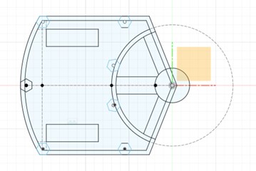
I tried to parametrize almost everything, so future adjustments would be easy. After reviewing the model, a few issues became obvious:
- The chassis is larger than necessary. No need for all that extra volume.
- The curved back wall looks nice, but it is not practical for manufacturing or assembly.
- Too many sharp edges. Some chamfers are needed.
- The screw holes on the plates were based on hex-head sizes instead of screw diameters.
- The wheel openings were too small. This becomes clearer in the Drive section.
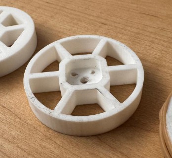
Version 09
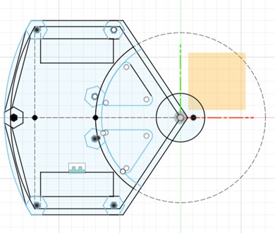
Version 09 is smaller, cleaner, and fixes many of the issues from V06. Still, after looking at it more closely, a few things stood out:
- There are still sharp corners. Why they survived to V09 is a mystery.
- The weapon mount area could be redesigned to improve rigidity.
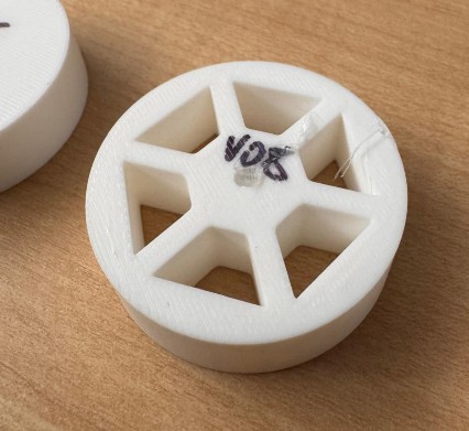
Version 11
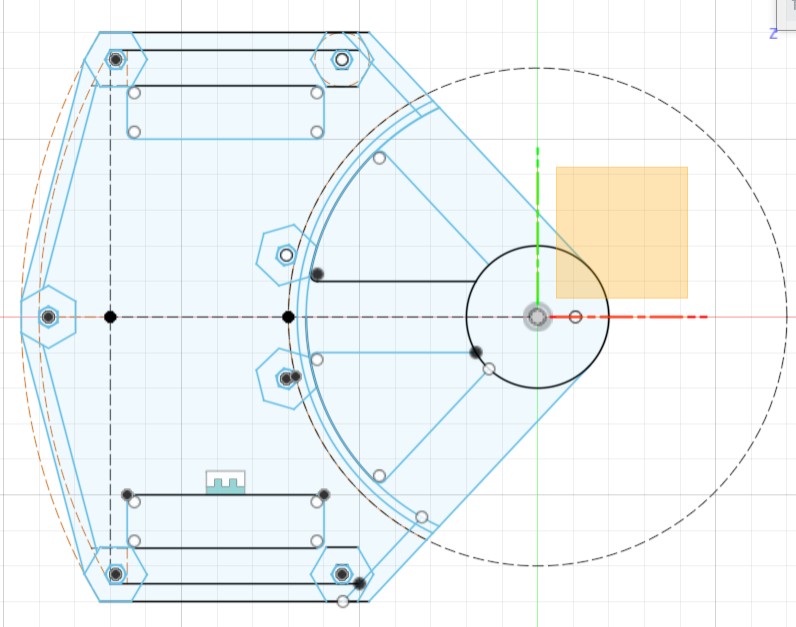
Version 11 addresses those issues and is basically the final plate geometry I committed to. However, later in the build process I realized I still needed to cut weight. Looking at other antweight robots, I noticed many used strategic cutouts. I also had to add:
- Screw holes for the weapon motor
- Screw holes for the wheel motor mounts
This led to the next iteration.
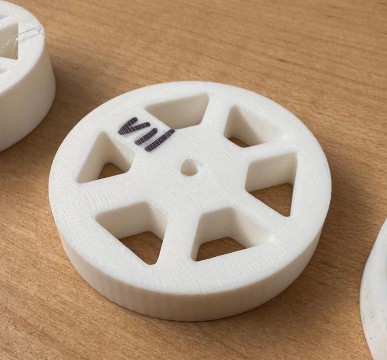
Version 18
This is the final iteration of the plate design.
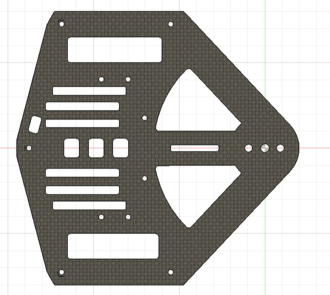
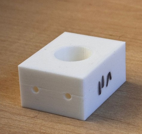
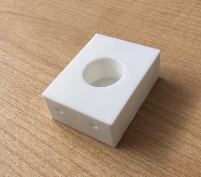
In Version 18, I added:
- The necessary screw holes for motors and mounts
- An access opening for the switch
- Additional lightening holes to reduce weight while keeping structural integrity
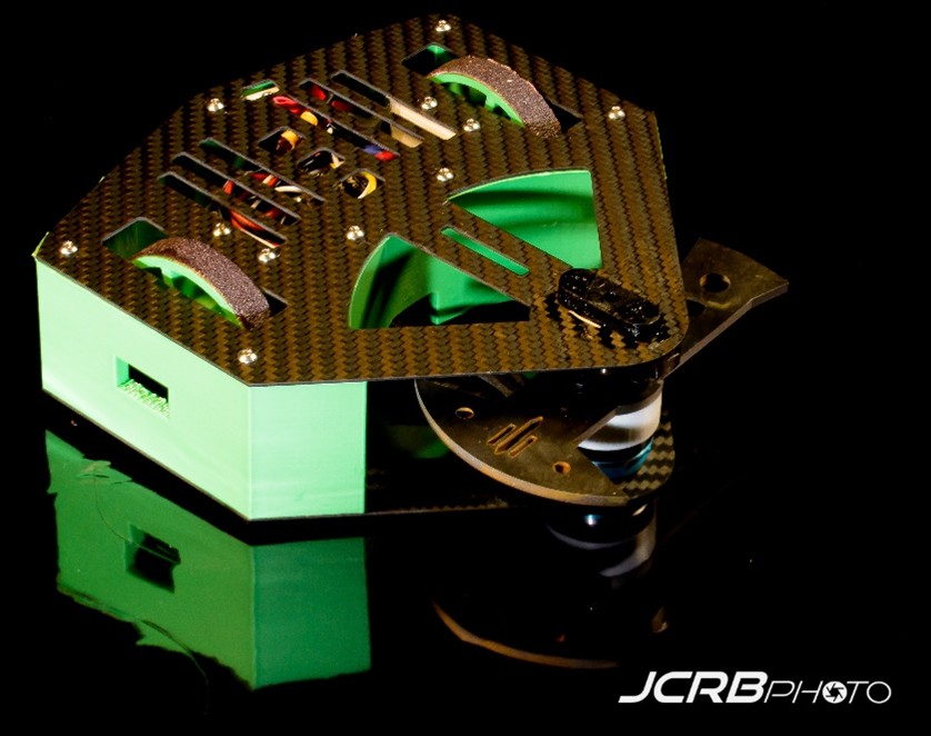
This version is the one I used for the build. The top plate and bottom plate are nearly identical, with the only major differences being the holes dedicated to the weapon motor mount.
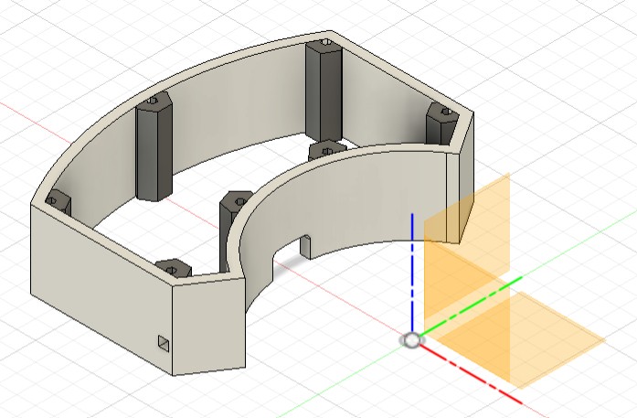
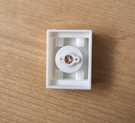
Walls Design
Version 08
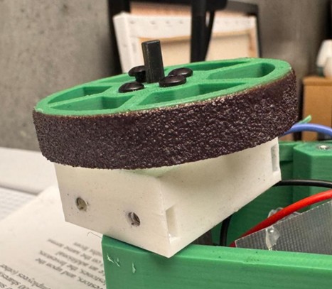
The plan for the walls was always to 3D print them in Super PLA for strength and impact resistance. Also, it’s key to keep the robot as thin as possible. I then decide to set the chassis height by the motor body plus the shaft stickout. This defines the maximum allowable height for the bot.
Note: I later (later later) realized you can actually cut the shaft shorter. This would have been good to know.
In Version 08, the first full concept took shape:
- 5 mm thick walls around the entire perimeter
- Integrated supports to hold the hex standoffs in place
- A front pass-through hole for the weapon motor wires
- Geometry meant to wrap the chassis like a rigid shell
The screenshot below is from a later plate version (after having shrunk the plates dimensions as per above), but the original concept was identical:
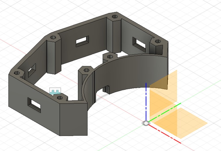
Version 12
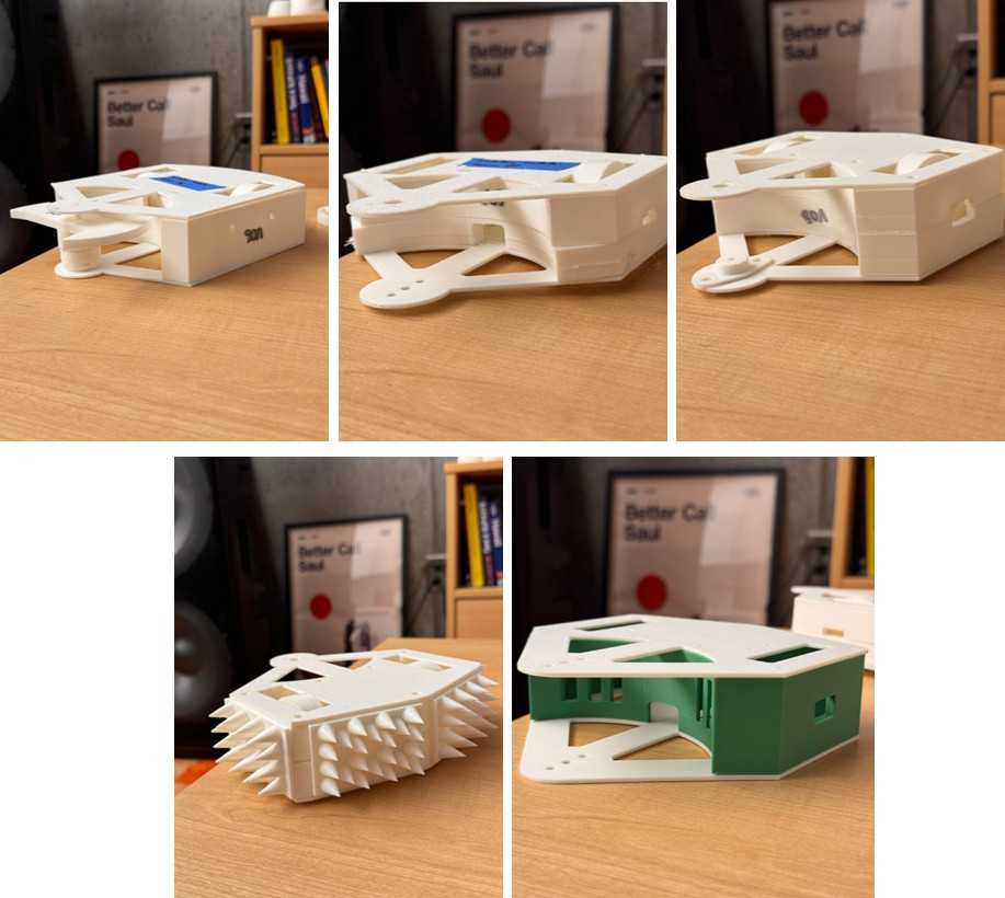
At this point I had an idea: adding an outer armor layer in TPU.
The logic was simple: TPU could absorb impacts rather than passing them directly into the PLA chassis.
To make this work, I:
- Split the walls into two parts
- Designed removable spiked armor plates
- Created slots for those plates to slide into
In the screenshot, I am showing one side with spikes and the other without for better understanding, but the idea is to have 4 sides with spikes.

I really wanted this feature to work. It made the robot look tougher and offered real protection. I kept it for as long as possible.
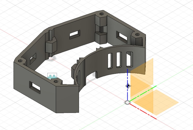
Version 14
By Version 14, the weight reality hit me. The TPU armor plates were simply too heavy, and keeping them would force a redesign of the walls to be much lighter (and not only the walls).
So the spiked plates had to go. RIP.
At the same time, I realized something important:
- I only needed thick 5 mm walls where the robot might actually take hits.
- The front wall, protected by the spinning weapon, does not need to be thick at all.
- So I reduced the front section to 2 mm to save weight.
- Since the spiky armor was gone, I no longer needed the wall split… but I kept the cutout slots for now, just in case.
Version 17
Version 17 happened very late in the process, during the phase I call:
“Vittorio realizing weight is the true final boss”.
I created this version as a panic lightweight edition, in case I really needed to shave grams:
- Added lightening holes in the front wall
- Reduced the PLA material holding the standoffs
- Simplified internal geometry to remove every non-essential gram
Spoiler: this version was not used, but having it ready gave me peace of mind.
Week 6 - Will it damage (eventually)?
Key considerations
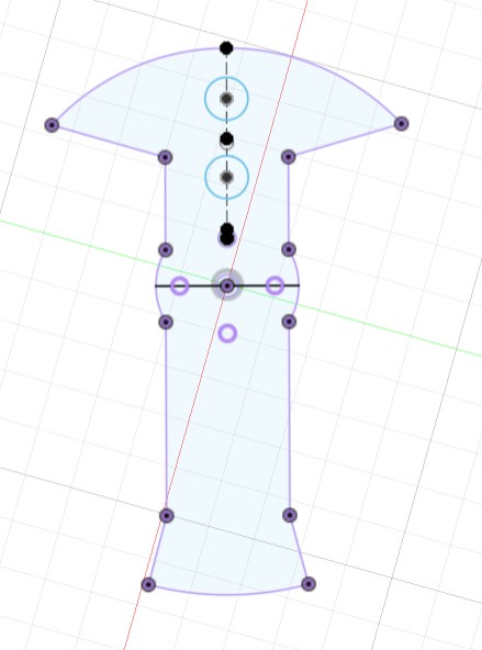
Since this robot is a horizontal spinner, everything meaningful about its offensive power depends on how well the weapon is designed. The starting point is always the same: the motor shaft axis, which defines the center of rotation. So, this axis sits at (0, 0) in my CAD model to keep everything symmetric and easier to tune.
This week I focused on understanding what makes a spinner effective rather than just “spinning fast”. Most of my learning came from the excellent YouTube lesson (132) Combat Robot Spinner Design Tutorial (Part 1): Theory and Math - YouTube
It explains the physics clearly and helped me translate theory into actual design decisions.
Here are the main principles I applied:
- Weight budget: In antweights, about 30-40 percent of the robot’s total mass is usually reserved for the entire weapon system. This includes the bar, hub, mounts, bearings, fasteners, and the weapon motor. Planning this early prevents building a weapon that consumes the full weight limit by itself.
- Diameter matters: A larger spinner diameter increases the moment of inertia, which increases the stored kinetic energy. Bigger diameter equals harder hits, but also more weight, more space, and more stress on the motor.
- Mass distribution: To maximize impact power, the mass must be placed as far from the rotation axis as possible. A heavier outer section dramatically increases rotational inertia.
- Weapon Geometry: Bars and disks are the two core spinner shapes: bars keep weight away from the rim while disks pack mass at the edge, giving disks higher energy storage but also more gyro forces, steering issues, vulnerability to off-plane hits, and poorer tooth engagement - so bars are usually preferred unless a disk has a very large tooth
- One tooth is better than many: A single-tooth bar delivers more energy per strike because it avoids double impacts and gives the weapon time to spin back up. The ideal rake angle is around 7 degrees, which lets the tooth “grab” the opponent instead of sliding across the surface.
- Tip speed limits: Tip speed must stay within safe and reasonable levels. Too slow and the weapon does nothing; too fast and it becomes unsafe and can tear the robot apart. Balancing RPM, diameter, and mass distribution is essential.
- Material and thickness: Most successful antweight horizontal spinners use hardened steel at 1/8 inch or 1/4 inch Thinner is faster, thicker is stronger. The right choice depends on motor capabilities and weight constraints.
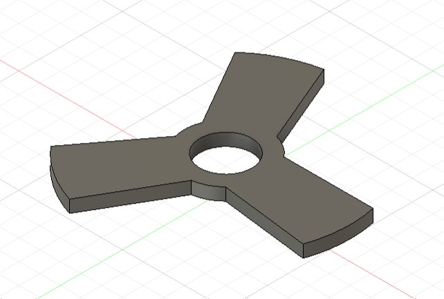
Weapon Design
Version 01
Designing the weapon is one of the most important parts of this robot. I started by choosing a spinner diameter based on reference antweight robots and decided to keep that diameter fixed for the entire design process.
In Version 1, I explored a three-tooth bar, cut from ¼ inch hardened steel. At the time, I didn’t yet understand/know many of the design rules described above, so several issues only became clear later.
The main flaws here were:
- A single tooth is more effective than three
- The central hole had no mounting logic yet
Version 04
Version 4 fixes the major issues from V1. I redesigned the weapon from three teeth to one and began thinking seriously about how to mount it.
I created a motor cap (to be printed in PLA) that would sit between the weapon and the motor so the steel bar would not rub directly on the motor face. I also added four screw holes in the weapon so the cap and motor could be fastened together.
At this stage, the cap was also designed to extend into the weapon, hoping this interlock would keep everything stable.
Looking at this version, two questions emerged:
- Is the weapon too heavy at ¼ inch thickness?
- I can mount the motor to the bottom plate easily, but how do I secure the shaft to the top plate? I clearly needed a bearing solution.
Version 06
Version 6 addresses both the weight and the mounting issues.
- I reduced the weapon to ⅛ inch hardened steel, which is more standard for antweights. Few robots actually use ¼ inch unless the design is very compact or the bar is extremely short.
- I designed a ball bearing mount (printed in PLA) to secure the shaft to the top plate. The mount was sized to hold a bearing with a 4 mm inner diameter, matching the weapon motor’s shaft.
- The plan was to press-fit this bearing mount into the top plate, holding the bearing in place.
At this stage, I did not realize how crucial this bearing mount would be, so it stayed almost unchanged for many versions while I focused on the weapon itself.
Questions now were:
- Is the bearing mount design correct?
- Is the weapon properly balanced?
Version 12
By Version 12, I had learned much more about how real antweight weapons are built. One key discovery was that none of the robots I studied used a motor cap that extended into the weapon. Instead, almost all of them used:
- a flat PLA motor cap,
- and four direct screw holes in the steel bar that tighten the weapon, cap, and motor together.
This system is simpler, stiffer, and has fewer points of failure. So I switched to this more standard mounting style.
This was also the moment when I first tried to balance the weapon. I incorrectly assumed that as long as the weapon had the same amount of surface area in the front and the back, the mass would be balanced.
Since the back half had more surface area, I added two circular cutouts to equalize front and back.
This was my first attempt at “balancing” the bar.
The design at this point looked like this:
Of course, I was about to learn why this method doesn’t work at all (if the “why” is obvious to you, please remember I am a business student).
Version 13
After adjusting the hole placement slightly, I decided to fabricate this version to test the real mounting.
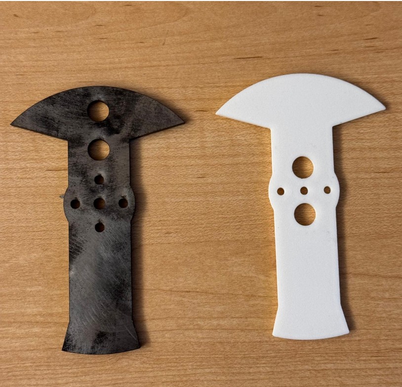
I laser-cut the weapon out of steel at the MAD shop - here you see it compared with the PLA prototype from Version 6.
This is when I had the big realization.
When checking Fusion’s part properties, I noticed the center of mass was clearly not at (0,0).
Since I designed the weapon to spin around the motor shaft (which is at 0,0), this immediately told me: the weapon was unbalanced.

Why the “equal area” approach completely failed? Here is what I learned:
- Balance does not depend on equal areas, it depends on mass distribution relative to the axis of rotation.
- The farther mass is from the center, the more it affects inertia.
- A gram of steel at the tip influences balance much more than a gram near the hub.
- My approach only equalized area, not radial distance weighted area.
- Therefore, the center of mass ended up shifted, even though the surface areas looked “balanced”.
In simple terms
- I thought: “Front and back have the same area, so it’s balanced.”
- Reality: “What matters is how far the mass is from the center, not how much area there is.”
This made Version 12 unusable. Time to redesign the bar.
Version 16
Version 16 is where everything finally came together.
This redesign solved two critical things:
- Weight reduction - I added carefully placed cutouts to drop unnecessary mass and stay within the antweight limit.
- True balance - I parametrized the hole radii and positions, adjusting them until the center of mass in Fusion was exactly at (0,0).
This was the first version that:
- matched the expected weight,
- had a correct center of mass,
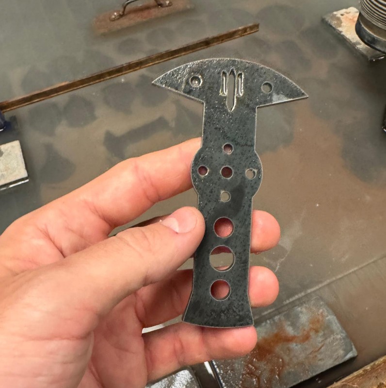
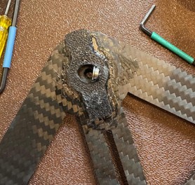
So, it could actually be cut in hardened steel with confidence. Since everything aligned with expected values, I went to N51 and water-jetted it out of hardened steel.
The only remaining issue was the bearing mount. Up to this point, the bearing mount design had not received much attention, but it became obvious that it needed improvement.
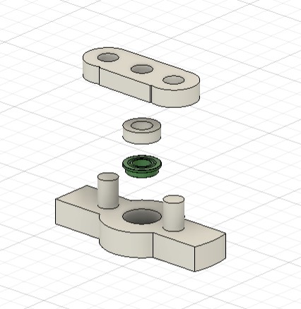
Version 19
Version 19 is the final meaningful version in the weapon subsystem, and it addresses the bearing mount problem once and for all.
During spin testing (and if you keep reading this journal you'll realize when this V19 took place), I realized something alarming: the press-fit bearing mount used in previous versions was not tight enough and would vibrate, shift, or partially pop out when the weapon spun up.
This was unacceptable. The bearing mount is what keeps the entire weapon shaft aligned with the robot.
So I redesigned the mount as a four-piece assembly, stacked vertically:
- Ball Bearing Mount Frame
- Printed in PLA
- Thicker walls for strength
- Has a recess that holds the bearing from below so it cannot fall downward
- Positions the bearing slightly lower than before for better support
- Ball Bearing
- 4 mm inner diameter
- Sits inside the mount frame
- Spacer
- A PLA cylinder matching the outer diameter of the bearing
- Prevents the bearing from moving upward
- Does not interfere with the bearing’s rotation
- Top Holder
- Snaps into extended posts coming up through the top plate
- Locks the entire bearing assembly in place
- Ensures the mount cannot shift vertically during impacts
Finally, everything is superglued in its final position for full rigidity.
Week 7 - Will it (barely) move?
To make the robot move, I needed a complete drive module, which consists of two things:
- A wheel that fits tightly onto the motor shaft
- A motor holder that locks the motor firmly to the chassis plates
Since I am sourcing the motors from Repeat Robotics, my focus this week was on designing the wheel and designing the mount that snaps correctly into the plates.
Wheel Design
Version 06
I began with the assumption that wheels were relatively simple: a cylinder extruded from a sketch, with an internal hole matching the motor shaft profile. The drive motor shaft is not a perfect circle. It has a flat side (a D-shaft), so I designed the internal hole to match that exact geometry.
For the first versions, up to V06, the design was simply:
- A cylinder
- A D-shaped internal hole to press-fit onto the shaft
After printing them, one thing became obvious: the wheel was too chubby and too heavy. I could have reduced weight using infill settings, but most antweight wheels have cutouts instead, so that became my next step.
Version 08
In Version 08, I added cutout holes to lighten the wheel while keeping the same diameter.
After looking at the printed result, I realized:
- I could design the holes more efficiently (not sure why they look so rushed?!)
- The wheel did not extend high enough beyond the chassis walls. As of now, the wheel diameter is parametrized to be equal to the walls height + 0.5cm. I think this is not enough
- The wheel was too thick at 1.5 cm, there is room to reduce.
So more redesign was needed.
Version 11
Version 11 addresses those issues.
- The wheel diameter was better parametrized so it now sticks 0.5 cm above and below the chassis walls

- The wheel thickness was reduced from 1.5 cm to 1 cm
- The holes were chamfered for strength and aesthetics
However, after increasing the overall diameter, I accidentally introduced asymmetry in the hole pattern.
I only noticed this later when reviewing the printed wheel, and knew I had to go back to cad to adjust it.
Version 15
This was an important milestone: I discovered screw hubs. What are screw hubs? A screw hub is a small square metal adapter that attaches directly to the motor shaft. It solves two problems:
- The shaft is a D-shape, so the hub has two screws that grip it securely
- The hub has threaded holes that let you screw the wheel onto it
In other words: the hub grips the shaft, and the wheel grips the hub. This creates a much more reliable connection than relying on a printed D-hole.
To integrate the hub:
- I imported the screw hub model into Fusion
- I subtracted its geometry from the center of the wheel
- I added screw holes to mount the wheel onto the hub
- And because weight was stressing me out by this point, I made the holes thinner and lighter (also addressing the v11 asymmetry issue)
After printing and testing, this wheel felt correct. The last remaining problem was grip.
Version 18
Version 18 is nearly identical to Version 15. Only the screw-hole dimensions were slightly adjusted for better fit. Now I needed to solve traction.
|
Option |
Description |
Pros |
Cons |
|
Leave wheel as-is |
Use the printed PLA surface with no added grip. |
Already finished, zero extra work. |
Very low traction, poor acceleration, poor control. |
|
Add PLA bumps/spikes |
Add small raised bumps or spikes directly in the wheel’s CAD model. |
Easy to model and print. No extra materials. |
Wears out quickly, practically no antweight robots use this because PLA has poor friction. |
|
Rubber inserts |
Add grooves or slots in the wheel to embed pieces of rubber. |
Good grip, I have seen it in competitive robots. |
Requires redesigning the wheel geometry, more testing, more printing. |
|
Metal traction rings/spikes |
Laser-cut thin metal rings with spikes, mounted on the wheel sides. |
Excellent traction on many surfaces, durable. |
Requires laser cutting, extra parts, more weight, more steps in assembly. |
|
Cast wheels |
Create a mold and cast wheels in rubber or flexible plastic. |
High performance, customizable hardness and texture. |
Typically too heavy for antweights, more complex process, longer production time. |
|
Glue rubber bands |
Stretch and glue rubber bands around the wheel perimeter. |
Light, cheap, reasonably effective when it works. |
Sensitive to glue amount (too much = stiff, too little = slips off), risk of rubber entering the drivetrain. |
|
Glue sandpaper |
Glue strips of 80-grit sandpaper around the wheel. |
Very light, easy to attach, excellent grip, commonly used in antweights. |
Needs occasional replacement after repeated impacts or abrasive surfaces. |
At this point in the project, I had two constraints:
- Very limited time
- A strict weight budget
I realized that in this specific moment, less is more.How many times at work have I heard this? Time to convince myself it’s actually good advice 😊. I didn’t need the perfect theoretical solution. I needed something effective, lightweight, fast to implement, and reliable enough for the upcoming competition.
Even though I identified a full range of possible solutions, I decided to test only two of them - the simplest and fastest - before going deeper:
- Rubber bands
- 80-grit sandpaper
Rubber bands worked at first, but getting the glue amount right was difficult. Too much glue made them stiff with almost no grip. Too little glue made them slip off, with a risk of jamming the motor or drivetrain.
Sandpaper, on the other hand, was:
- easy to glue
- lightweight
- stable during testing
- surprisingly effective
After a few quick tests, sandpaper became the final solution.
This completed the wheel module.
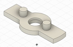
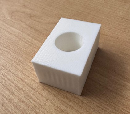
Motor Mount Design
Version 03
The first question was simple: how do I attach the drive motors to the chassis?
My initial attempt was a very early prototype: a rectangular PLA box with a circular pocket sized exactly for the motor diameter. The pocket did not go all the way through - I left a small floor to support the motor.
Version 03, however, had two major problems:
- It didn’t attach to the bottom or top plates 😅
- It didn’t actually hold the motor in place 😅😅😅
The only goal of this print was to check tolerances and confirm that the motor could fit snugly into the mount. And for that, it served its purpose.
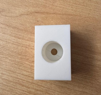
Version 11
With the tolerances confirmed, I tackled the real issues.
First: how to hold the motor inside the mount? The drive motor has two small screw holes on its face, so I added two matching holes in the mount. Now the motor could be screwed directly into the housing.
Second: how to attach the mount to the chassis plates? My first idea was to simply add holes for screws and hope the screws would hold everything in place.
Spoiler: they didn’t. The screws slipped out easily, and the mount offered no real structural
Version 14
Time to refine the design. Two goals this time:
- Reduce weight: I reduced the mount depth from 2 cm to 1.5 cm. This still held the motor securely while dropping a noticeable amount of mass.
- Fix the attachment to the plates: I tried making the screw holes smaller, hoping the screws would “bite” into the plastic. While this technically works, it’s a bad idea for repeated usage. In a real competition, I will likely need to remove the motor many times. Screwing directly into PLA wears the threads and eventually destroys the hole.
So this was not a good long-term solution. I needed something sturdier.
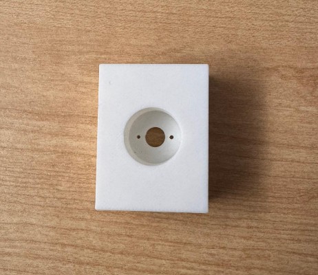
Version 15
Version 15 is where everything finally clicked. During HTMAA Machine Week, Neil explained a proper way to screw into 3D printed parts: create a pocket for a hex nut so the nut sits inside the plastic and the screw tightens into it. This solves everything:
- The nut provides real metal threads
- The screw can be removed and reinserted many times
- The plastic only holds the nut - it doesn’t bear the thread strength
- The mount becomes much more serviceable in battle
The other option would have been to use heat-set inserts, which melt slightly into the plastic and create threaded metal holes. They are too an excellent solution. But now that I am writing, I am trying to convince myself that they are worse off because they are heavier, harder to replace, and not as battle-friendly. So, it’s not even worth trying……. And I stuck with hex-nut pockets.
I also experimented with reducing weight by cutting large voids in the mount geometry using the Shell function in fusion. But in this specific part, it was better to reduce infill rather than cut away too much structure.
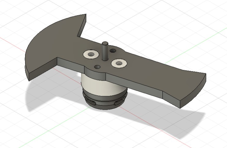
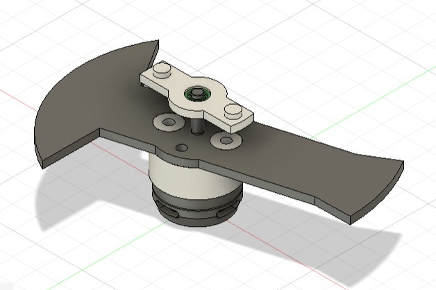
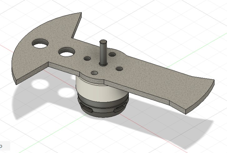
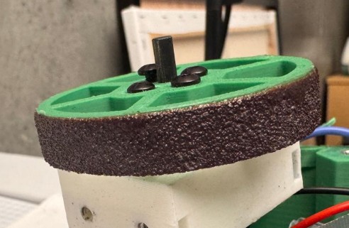
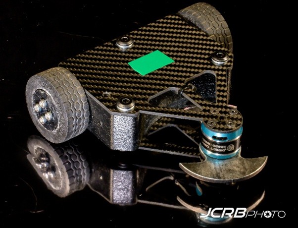
This completes the drive motor mount module. After assembling the motor mount and wheel together, here is the final look:
Week 8 - Discovering what doesn’t work (yet)
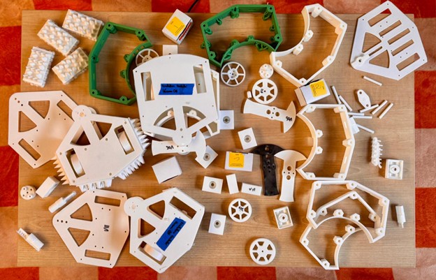
Prototyping
By Week 8, most of the robot existed in CAD - plates, walls, weapon, wheels, motor mounts. On Fusion everything looked reasonable. Which, of course, means: still untested in real life.
At this point in the project prototyping became the main job. Not as a final step, but as a way to answer very specific questions like:
- Does this actually fit?
- Is this too heavy?
- Will this break the moment I look at it funny?
- And why does it look so different from how I imagined it?
I also realized something simple but important: seeing the robot physically, even in rough PLA, is way more informative than staring at it from 12 angles in Fusion. You understand clearances, proportions, and “vibes” much faster when it’s sitting on the table in front of you.
I’ve printed many of these parts more times than I’d like to admit - and most of that is documented above. Here you can see a few key stages of the prototyping journey and, more importantly, the main lessons that came out of it.
Important note: I didn’t prototype “for fun” - I prototyped to answer one, two, or three focused questions at a time (rarely more than three). Each version existed to test something specific:
- Chassis plates → Is this size reasonable? Are the clearances enough? Did I put holes in the right places?
- Walls → Is 5 mm too thick? Does the height feel right? Does it match the Chassis dimensions?
- Weapon → Is it mountable? Does it spin without wobbling?
- Wheels → Is the diameter right? Is it too thick? How bad is grip in reality?
- Motor mounts → Does the motor actually sit snug? Can I screw and unscrew this without destroying the plastic?
Lastly, for prototypes, unless I was trying to print the actual part in actual weight, I almost always used these settings:
- Material: White PLA
- Printer: Bambu Lab P1S
- Nozzle: 0.4 Diameter with Standard flow
- Quality: default settings
- Strength: all default settings, except:
- Wall Loops: 2
- Sparse Infill Density: 8%
- Sparse Infill Pattern: Gyroid
- Speed: default settings
- Support: all default settings, except:
- Support type: tree (auto)
Testing parts
Key realizations from prototyping parts:
- The first chassis felt huge. On CAD, the extra volume looked harmless. In reality, it was wasted space and unnecessary weight.
- The curved back wall looked great in Fusion. Printed, it became clear it would be annoying to mount, annoying to machine, and annoying for everything else.
- Prototyping confirmed that setting the height by “motor + shaft stickout” worked visually - the bot looked low and compact - but it also made me realize (much later) that I could have simply cut the shaft and saved trouble. That’s the kind of thing you often only notice when you’re holding the thing.
- A TPU spike armor looked cool on screen and even cooler in person… but once printed and weighed, it screamed: this is going to blow the weight limit.
- The hole pattern asymmetry on wheels was something I honestly didn’t notice until I saw the printed wheel and thought: this looks wrong. CAD didn’t scream. The print did.
- The diameter being “walls height + 0.5 cm” sounded correct in CAD, but only once I had the robot on the table I realized it needed to stick out a bit more to look and drive right.
Partial assemblies
Some of the most useful prototypes were not single parts, but partial assemblies:
- Chassis + walls only
- Chassis + walls + weapon motor
- Chassis + drive module (wheels + mounts)
- Almost-complete robot with no electronics
These “fake full bots” were the first time the project actually started to look like a robot and not like a CAD. They proved to be essential for figuring out assembly and testing tolerances and mounts.
Key lessons from the prototyping journey
Looking back, there are a few general principles I’d keep for any future project:
- Prototype early and with a question in mind: Don’t print everything “just because”. Know what you want the prototype to tell you.
- CAD is necessary, but not sufficient: Symmetry, clearances, weight, grip, and “does this feel right?” often only become obvious when the part is in your hand.
- Start ugly, refine later: Early versions can look bad and be wrong. That’s their job. The point is to learn cheaply.
- Use cheap materials for expensive questions: PLA is perfect for test fit, assembly, and mounting before touching hardened steel or final prints.
- Design for serviceability, not just assembly: Prototypes exposed how annoying it is to remove parts repeatedly. Hex-nut pockets, accessible screws, and simple mounts all came out of imagining “battle repair” scenarios while holding the parts.
Week 9 - (Recklessly) Signing up for a competition
The safe choice
Wait… WHAT?
It’s late October, and I suddenly discover something mildly catastrophic: MIT Combat Robotics Club is hosting a House Battle for antweight and beetleweight robots on Saturday, November 15th.
Right here. On campus. In less than a month.
Meanwhile, I’ve attended maybe… three CRC meetings? They happen on Saturday afternoons and I had to skip many because.. well, because they happen on Saturday afternoons (I am only human).
And my robot? Let’s just say it’s in that awkward in-between stage where the idea is (almost) complete, but the physical object is mostly still hopes and few PLA prototypes. Here’s what’s still missing:
- Finalize some key parts
- Start (and finish) the entire electronics system
- Make sure the bot is within the 1 lb weight limit
- Source metal and carbon fiber
- Machine all the metal and carbon fiber
- Assemble everything
- Test it (and pray nothing explodes)
Also, I’m traveling for interviews during this period, so time is basically… nonexistent.
The rational, responsible, adult choice is obvious: Just finish the robot in December. Nice, calm, safe.
The choice that feels right
Except… no. I refuse. Sure, waiting until December would lead to a more refined robot.
More iterations. More testing. More improvements. A cleaner build. A stronger chassis. Maybe even a weapon that doesn’t terrify me as much as it terrifies others.
But here’s the truth: this project isn’t just about completing an HTMAA assignment. In Week 0 I wrote I was doing this for two reasons, with one being: “Prove a point: that the only thing between my childhood self and reality is actually doing the work.”
So tt’s about proving - to myself more than to anyone - that a business student with zero prior experience can actually build the combat robot he dreamt of as a kid. And what’s the point of a combat robot if it doesn’t… combat?
Could I wait until spring to compete? Yes.
Should I?
Absolutely NO WAY.
Because I’m at MIT.
Not just any campus.
Arguably the most intense engineering playground on Earth.
And depending on where you stand on extraterrestrial life… maybe in the entire universe.
This is the place to do ridiculous things.
Impossible things.
Things that 10-year-old me would brag about for the next 20 years.
So I’m committing:
- I will build this bot.
- I will finish it in time.
- And on November 15th, I will send it into the arena.
- Even if it does not
- Even if it is going to be destroyed in the first fight.
I already know that future-me will come back and read this line. And I hope he’s proud of the choice.
Spoiler? Naaah, keep reading!
A star is born
Now came a surprisingly difficult question:
What should I name my robot?
After building mechanical parts, designing weapons, calculating moments of inertia, and fighting Fusion 360 at 2 AM… you’d think naming would be easy. It wasn’t.
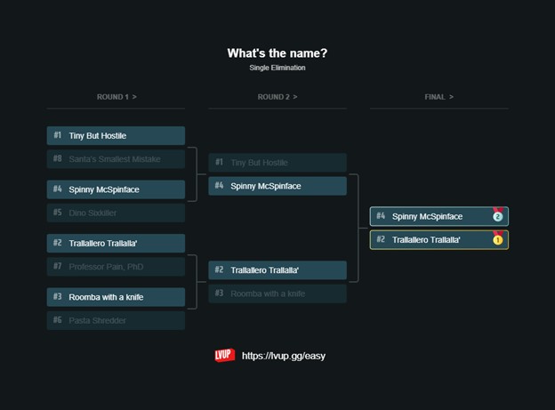
I gathered eight candidate names and recruited a small group of friends. Together we organized a naming bracket (because of course we did). Match after match, we argued, voted, defended our favorites, and slowly narrowed it down until only two finalists remained:
- Spinny McSpinface
- Trallallero Trallallà’
It was a tight race. The jury was divided. But in the end, by split decision, the winner emerged:
👉 Trallallero Trallallà’
And that was the moment it all clicked.
After two months of CAD, prototypes, and redesigns, the project finally had an identity.
Signing up
Once the name was chosen and I had officially convinced myself (and my friends) that this was happening, the next step is obvious.
No more hesitating.
No more “maybe next semester.”
I opened the competition page, entered Trallallero Trallallà’ into the registration form, and submitted it. Just like that, it became real. The bot was signed up for its first-ever competition.
And now the clock is ticking.
Week 10 - Getting the wiring right (ish)
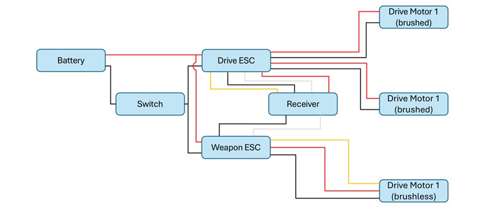
The schematics
I picked my motors and electronics early on, but I never fully understood how each part worked. HTMAA made me realize how much I struggle with electronics, and with a fight in less than 10 days this could easily become a roadblock. So I have just put my mind on this, and here is a simple breakdown of what each component actually does:
- Battery: Provides all the robot's power. LiPo batteries have an excellent power-to-weight ratio and can deliver very high current quickly, which is ideal for short combat matches. They are fragile and can catch fire if damaged or charged incorrectly, so they must be protected and charged carefully.
- Switch: A mechanical power cutoff for the whole robot. Competitions require it to be easy to access and able to shut everything down instantly.
- ESCs (Electronic Speed Controllers)
These take signals from the receiver and power from the battery to control motor speed and direction. Robots use multiple ESCs wired in parallel, never in series. - Brushless ESCs: They have three output wires that connect to the three motor phases. If the motor spins the wrong way, swap any two wires.
- Brushed ESCs: They have two output terminals for the two motor leads.
- Brushed Motors: Two-wire motors that spin based on input voltage, throttle, and motor specifications. They use brushes and a commutator to energize coils on the rotor. They are simple and inexpensive but less powerful than brushless motors.
- Brushless Motors: Three-wire motors with no brushes or commutator. They rely on the brushless ESC to time the phase pulses correctly. They cost more but are far more powerful and are commonly used for both drive and weapon systems.
- Receiver: It receives commands from the transmitter and sends them to the ESCs. It needs its own low-voltage supply, usually around 5 V, so the main battery voltage has to be stepped down before powering it.
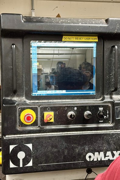
So, after having done this research, I am pretty confident the General Wiring Diagram for my bot needs to look something like this:
Soldering
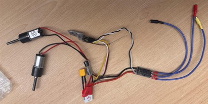
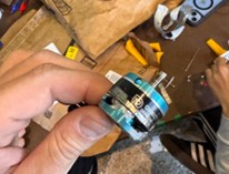
I did all my soldering in a single session at MITERS at 11 pm on a Saturday night. MITERS is a super cool makerspace and lab on the ground floor of N51, packed with tools, random parts, and more chaos than I expected, but perfect for this kind of work. I set up a light and cleared just enough room on a very crowded table, then grabbed four “third hand” tools that made me feel like Doctor Octopus in Spider-Man. The soldering itself went smoothly and everything worked on the first try. The third hands were especially helpful when I had to join the battery leads to both ESCs, which required holding three cables together at once.
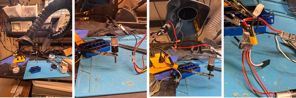
At the end, I covered all exposed joints with electrical tape and also electronics was covered.
Week 11 - Putting it all together (finally)
The deliverables
Today is Wednesday, November 12. On Saturday, November 15, my robot needs to compete. A lot still has to happen. It’s officially full pedal to the metal — time to stock up on coffee, Red Bulls, and questionable levels of determination, and make sure I deliver on the commitments I’ve made.
Here’s what still needs to get done:
- Finish printing all remaining parts
- Cut the weapon from AR-hardened steel
- Cut the top and bottom plates from carbon fiber
- Assemble everything together
- Test it
Printing parts
The plan from the beginning was to print most parts (e.g., wheel holders, weapon cap, etc.) in normal PLA and the walls and wheels using Super PLA rather than regular PLA.
Why? Because Super PLA is essentially PLA that’s been modified for higher impact resistance, better layer adhesion, and greater overall toughness. It’s not as flexible as TPU and not as heat-resistant as PETG, but for combat robots - especially antweights - it hits a sweet spot:
- Much stronger than standard PLA
- Still easy to print
- Less brittle, which helps during side impacts and glancing hits
In other words, Super PLA gives you most of the convenience of PLA, but with mechanical properties that make it far more suitable for a bot that is expected to get punched in the face repeatedly.
Since I wasn’t sure the Architecture Shop had Super PLA available — and considering my very tight timeline — I reached out to the CRC team to see if anyone could lend me a roll. (They did. Heroes.)
At this stage, the wall design is fully locked in. Not only the walls, the full robot is indeed. The version heading into battle is V19, which you can download here:
TrallalleroTrallalla'-v19.stl
For material, I chose Overture Super PLA in Green. Most settings are fairly close to standard PLA, with a few tweaks for strength:
- Printer: Bambu Lab P1S
- Nozzle: 0.4 Diameter with Standard flow
- Print temperature: 240 degrees
- Fan speed: 50%
- Quality: default settings
- Strength: all default settings, except:
- Wall Loops: 4
- Sparse Infill Density: 40%
- Sparse Infill Pattern: Gyroid
- Speed: max 50mm/s
- Support: trees (auto)
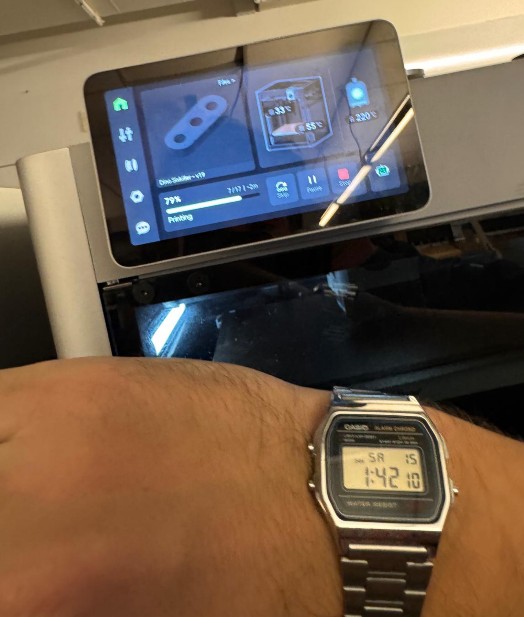
To maximize toughness, you can notice there are three key adjustments recommended by the CRC (and many experienced builders from different blogs). The first is increasing the nozzle temperature to around 240°C. This is higher than what most Super PLA brands officially suggest, but the extra heat dramatically improves layer adhesion and overall impact resistance. The print quality drops slightly, but that’s a small price to pay.
The second adjustment is reducing both cooling and speed. Running the part cooling fan at roughly 50 percent and keeping print speed around 50 mm/s allow the layers to fuse more completely, reducing brittleness and increasing durability during impacts.
Lastly, is to increase strength, both in terms of wall loops and sparse infill. I was advised to print at least 3 wall loops, and to not increase infill over 40-50% because it would practically be the same.
With this setup, the prints came out strong, rigid, and genuinely battle-ready — exactly what Trallallero Trallallà’ needs. Since I was worried that weight might still become a problem, I printed two versions of the walls: a standard version, and a lighter one with additional cutouts to shave grams (see Week 5 for the full story). For the wheels, one well-tested design was enough.
I printed the rest of the parts out of normal white PLA.
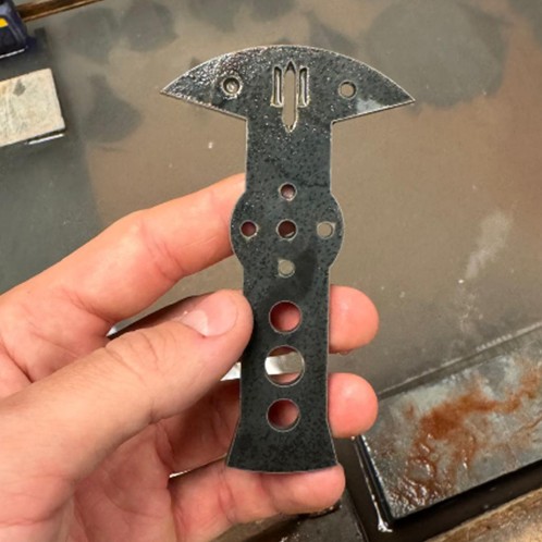
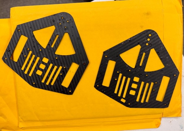
Cutting the weapon
For the weapon, I needed AR500 steel, 1/8 inch thick. I didn’t have direct access to this material, but fortunately the CRC team had some in stock and let me use it. Lifesavers, once again.
Using a laser cutter
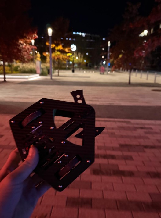
I had already cut an earlier version of the weapon about a week before, using the laser cutter, in particular the fablight fl4500 laser cutter , but later discovered that version wasn’t balanced. I just realized I hadn’t properly documented that process, so here it is. All of this work took place in the N52 Fabrication Shop on the 3rd floor of the MIT Morningside Academy for Design (MAD).
To prepare the steel, I first cleaned its surface with a grinder to remove any impurities.
Then, with help from the shop manager, I walked through the cutting workflow. The steps were: exporting the weapon’s profile as a DXF, loading that file into the laser cutter software, selecting the correct material type and thickness and exporting the file to an USB.
After loading the file in the machine, the only thing left is setting the origin using the laser pointer, and finally starting the cut.
A few minutes later, the weapon was fully cut - clean, sharp, and ready for the next stage (which it never reached because it was not balanced ☹).
Using a water jet
I’m back in N52, but this time on the ground floor, right next to the wood shop. This area hosts the MakerWorkshop, an extremely impressive student-run mechanical engineering space. It’s packed with everything you could ever want for building things: multiple types of 3D printers, two laser cutters, a precision lathe, a waterjet cutter, a CNC mill, and more power tools than I can reasonably list. I’m here for one thing: the OMAX 5555 waterjet.
The OMAX 5555 is a high-performance abrasive water-jet system designed for cutting a wide range of materials, from hardened steel and composites to thick metals and plastics, with micron-level accuracy. It features a cutting envelope of 4’ 7” by 4’ 7” (≈ 1.39 m × 1.39 m), giving you plenty of room to cut large parts or multiple small parts in one go. Key technical highlights include:
- ±0.001” (±0.025 mm) positional accuracy, ensuring cut parts are extremely precise.
- A submerged tank design that keeps the cutting quiet (below ~80 dB) and helps trap abrasive and particles safely.
- The ability to machine materials without creating heat-affected zones
- A footprint of about 11’ 5” × 8’ 9” (≈3.48 m × 2.67 m) including the pump, making it large but manageable
After doing more research, I learned that many experienced combat-robot builders prefer waterjetting their weapons instead of laser cutting them. AR500 steel is hardened through heat treatment, and exposing it to high heat (as with a laser) can soften the steel near the cut edge, reducing durability. For an antweight, the difference is probably negligible - but let’s be honest, the waterjet is awesome, and I wanted the strongest possible version of my weapon.
With some help from the shop manager, I got the cut underway. The workflow is similar to the laser cutter, but with a few extra steps. I exported the weapon profile as a DXF, powered on the waterjet and its computer, and waited the recommended 20 minutes for the system to come fully online.
Then I loaded the file, selected the material type and thickness, confirmed the toolpath, secured my steel plate onto the cutting bed, set the nozzle height and origin, and finally launched the job.
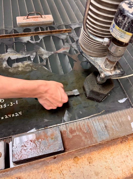
Just a few minutes later, the machine finished, and I had a perfectly cut, waterjetted weapon ready to mount onto the robot.
Cutting the plates
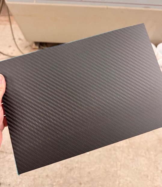
Warning: this is where I hit the biggest hurdle of the entire project.
From the start, I knew my top and bottom plates had to be carbon fiber, ideally 1 mm or 2 mm thick. Almost no antweight builder uses PLA plates — especially not when the weapon motor mounts directly onto them. PLA flexes, softens under heat, and can crack under repeated impacts. A spinning weapon transfers huge loads through the motor mount into the plate, and if the plate flexes even a little, the weapon shaft misaligns and the entire robot becomes unstable. In short: PLA plates = no.
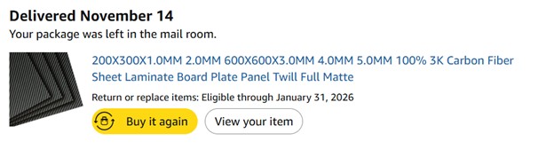
So last week, I ordered two carbon fiber sheets on Amazon — one 1 mm thick, one 2 mm thick (20×40 cm each). No local shop in Cambridge sells carbon fiber sheets, so Amazon was my only real option.
Here’s the product: Amazon.com: 200X300X1.0MM 2.0MM 600X600X3.0MM 4.0MM 5.0MM 100% 3K Carbon Fiber Sheet Laminate Board Plate Panel Twill Full Matte : Industrial & Scientific
I wanted both thicknesses because I still wasn’t sure where my weight budget would land, and I wanted to feel how rigid each sheet was in person. Once they arrived, I realized 1 mm was more than enough, so the thinner plate became my default.
Then came the plot twist.
On Monday, I realized that the latest chassis update made my top and bottom plates too big to fit together on a single 20×40 cm sheet. Their total area is under 800 cm², but their shapes meant they no longer fit side by side. So I ordered two more 1 mm sheets. Delivery estimate: 1–2 days. Perfect. I planned to cut them Tuesday or Wednesday.
That dream lasted about 12 hours. Amazon delayed delivery to Thursday.
Annoying, but survivable - I’d cut them Thursday.
Then Amazon delayed again to Friday. At this point, I felt personally betrayed. Mr. Bezos, why? I needed those plates. They are critical structural parts. Yes, I could have printed them in PLA, but it would have been weaker, heavier, and unsafe. I could have switched to aluminum, but that would require changing thickness, rebalancing the weight, and redoing the CAD. I needed carbon fiber. Full stop.
On Friday morning, I still had no carbon fiber. And I had to cut the plates that same day.
Cutting carbon fiber requires a waterjet, because cutting it with a saw or a CNC releases toxic carbon dust that you must never inhale. Underwater cutting traps the dust - safer for everyone. Even drilling additional holes must also be done underwater. This means the waterjet is non-negotiable. So I booked the waterjet at 4 PM, crossed my fingers, and hoped the sheets would arrive in time.
At 3:00 PM, the package finally showed up. Mr. Bezos came in clutch at the last possible second.
I jumped on a BlueBike, rushed to N52, and arrived just in time for my 4 PM reservation - only to find that the person before me had machine issues. Everything was delayed by two full hours. At 6 PM, I finally got access. In thirty minutes, I prepped the material, set the file, calibrated, cut both plates, and…it worked.
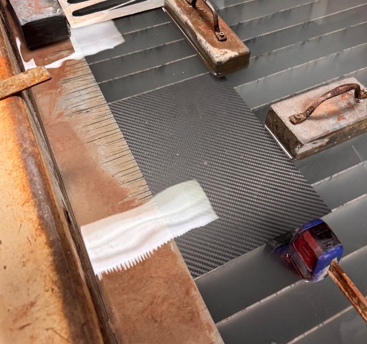
Perfect cuts. Zero issues.
After days of delays, stress, and uncertainty, I finally had every single part I needed. Time to start assembly.
Assembly
Finally time to put everything together. The competition is in 12hours. Here are some parts I purchased off McMaster-Carr essential for the assembly:
- 10x Lightweight Aluminum Female Threaded Hex Standoff, 3/16" Hex Size, 1-5/8" Long, 4-40 Thread Size, at $1.74 each. Link here: https://www.mcmaster.com/catalog/131/3737/91780A552
- 100x 18-8 Stainless Steel Button Head Hex Drive Screw, 4-40 Thread Size, 1/4" Long, at $3.82 per package. Link here: https://www.mcmaster.com/catalog/131/3445/92949A106
- 2x Flanged Ball Bearing, Steel, Open, Trade Number 74, at $11.14 each. Link here: https://www.mcmaster.com/products/57155k437/
- 100x Lightweight 6061 Aluminum Hex Nuts, 4-40 Thread Size, at $6.79 per package. Link here: https://www.mcmaster.com/products/93181a003/
- 100x 18-8 Stainless Steel Button Head Hex Drive Screw, 4-40 Thread Size, 5/16" Long, at $3.88 per package. Link here: https://www.mcmaster.com/catalog/131/3445/92949A107
- 1x Easy-Align Ball-Tip Hex L-Key Set, Long Length, 8 Pieces, Black Phosphate-Coated Steel, at $9.23 per package. Link here: https://www.mcmaster.com/products/5709a16/
Other screws were needed for motors, but most times they came already with their parts.
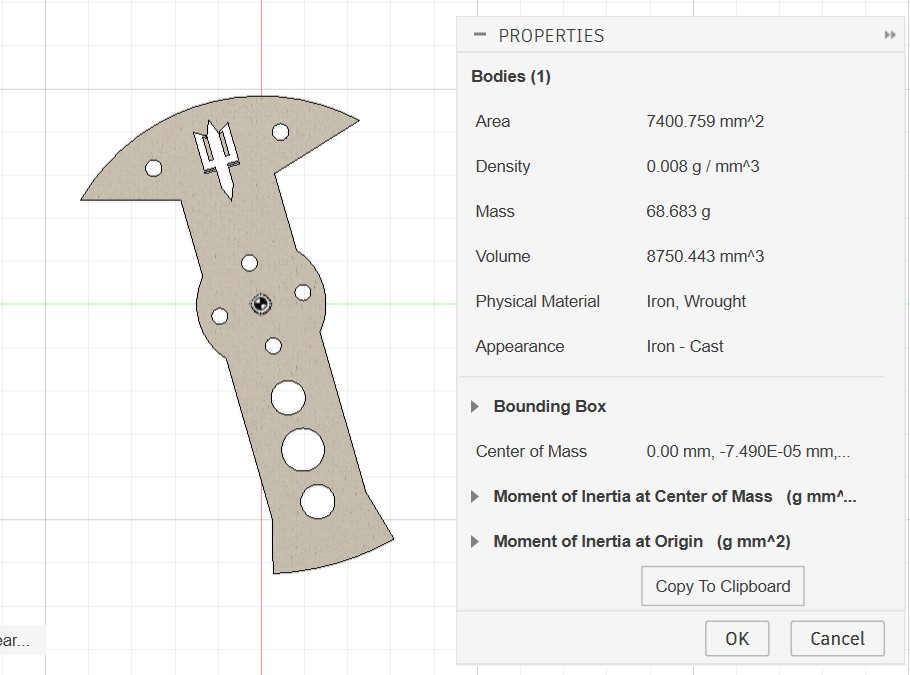
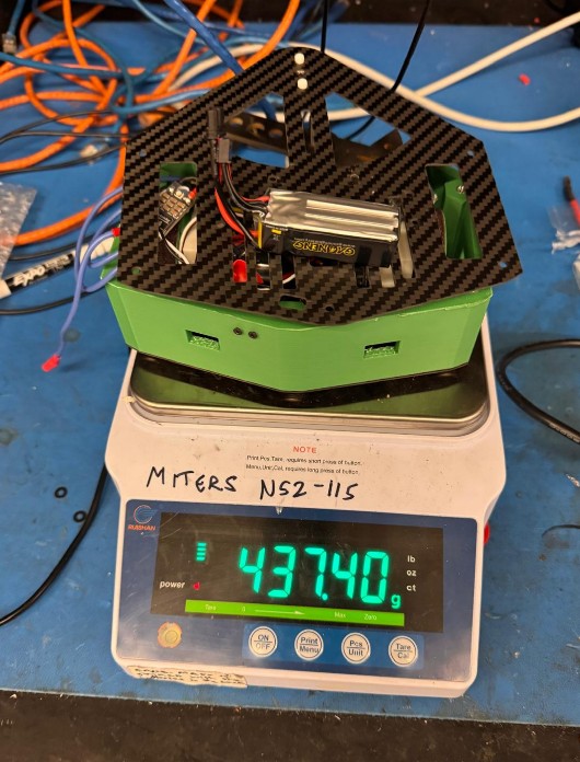
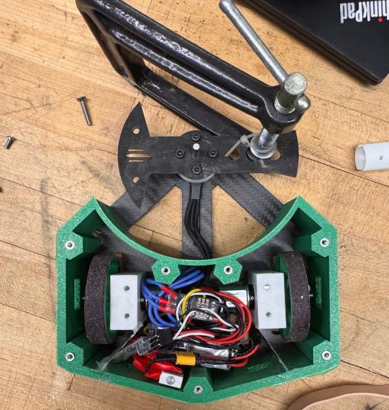
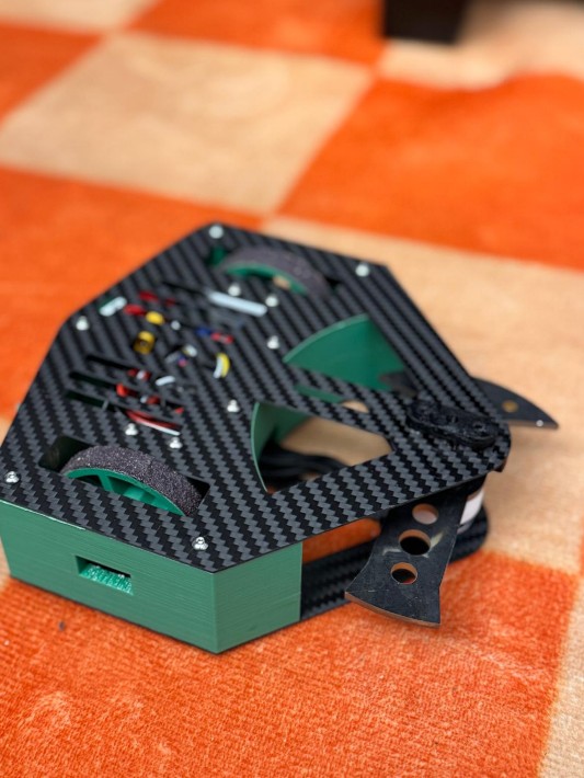
Now that I finally had all the components, I weighed the full assembly. The total came out to 437 g, comfortably under the 453 g antweight limit. For the first time in this entire process, something about the robot required no emergency redesign. Weight is officially good!
With everything finally ready, I began putting the robot together. The assembly sequence went roughly like this:
- Press-fit the standoffs into the walls
- Mount the wheel motors onto their motor holders
- Fix the screw hubs onto the motor shafts
- Screw the wheels onto the hubs
- Fasten the wheel motor mounts to the bottom plate
- Attach the motor mounts to the bottom plate
- Attach the walls to the bottom plate
- Mount the switch onto the walls
- Bolt the weapon onto the weapon motor
- Mount the weapon motor onto the bottom plate
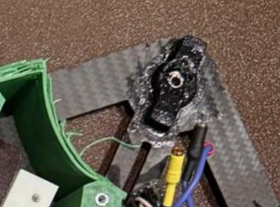
- Install the ball-bearing assembly onto the top plate
- Route and connect all electronics inside the chassis
- Close everything by attaching the top plate to the walls
And just like that - after weeks of CAD, prototyping, machining, stress, and caffeine - Trallallero Trallallà’ is officially assembled.
Testing
By the time I finish dinner and assemble the last components, it’s already 11 PM. There’s only one thing left to do: make sure everything actually works. Trallallero Trallallà’ looks like a robot now — but until it moves, it’s just modern art.
Connecting
To test it, I need a transmitter. Earlier this week I had asked the CRC if someone could lend me one, and fortunately they could. Before using it, I spent some time researching how transmitters work in combat robotics, because I wanted to understand what I was actually holding in my hands.
In RC systems, there are two main families of transmitters:
- Air transmitters are the classic drone/airplane-style controllers — usually a rectangular unit with two gimbal sticks and extra switches, knobs, or sliders. They give you fine control and multiple channels, which is why most combat robots use them. The stick layout maps perfectly to differential drive: CH1 and CH2 control the drive ESCs, letting you mix them together for smooth “arcade-style” driving on a single stick. CH3 usually manages the spinner weapon (it’s the throttle channel, without spring return), and CH4 is used for weapons that need bidirectional movement, like lifters or hammers.
- Surface transmitters, or pistol-grip controllers, are used for RC cars. They have a trigger for throttle and a steering wheel for direction. Great for cars, not so great for robots with multiple systems and no front-facing orientation.
Given all of this, I went with an air transmitter. The CRC had a FlySky FS-i6, which is one of the most popular beginner transmitters in combat robotics. It’s affordable, easy to configure, and uses the AFHDS 2A protocol, which is also supported by my receiver - meaning everything is compatible.
The best part? Tom from the CRC was still in the shop at that hour. He helped me bind the transmitter to Trallallero and walk through the initial configuration. Without him, I’d probably still be staring at the menus, wondering why nothing was moving.
Driving
The first step was simple: get the robot to move. Even the smallest twitch would confirm that the wiring, ESCs, and receiver were all talking to each other. So I spent a good 30 minutes driving the bot around with the weapon motor unplugged. To my surprise — and relief — it moved smoothly, responded well to inputs, and the sandpaper on the wheels actually worked. The grip was solid.
Testing the weapon
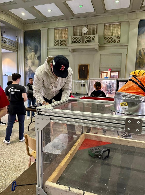
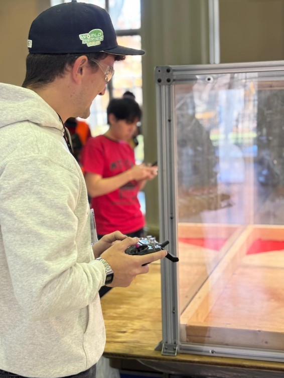
Ok, so now we are far past midnight. Only thing needs to test is if this bot can actually do some damage or not. I have been adviced that Spinning weapons should NEVER be powered on outside of an enclosed test-box – if you want to test outside of an enclosure, make sure to unplug the motor or remove the weapon belt. This includes testing at low speeds, as well as plastic prototype weapons – these are dangerous too!
And I will follow this advice. Luckily, in the Milkdrop room at the 3rd floor of N52 there is exactly the test-box I need. It is a 1.5m x 1.5x square box with a 1inch thick plexiglass lid. I open it and try to spin the weapon. I really fear it, for some reason, everything might break. So I start slow, spin the wepon to 10%, all good. 20%, good. 40% good. 50% good. Then 70%... and it works just fine!!
I play with this a few minutes, hitting some of the scraps in the box, until trallallero shakes a lot and I see some white PLA flying around. I turn this off and I notice that the mount that I had in place to secure the top of the shaft of the weapon motor to the top plate came off loose. In this moment, I regret the moment in which I choose to have a pressfit part instead of designing something with screws and bolts.
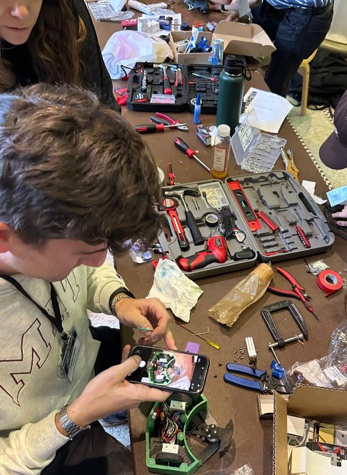
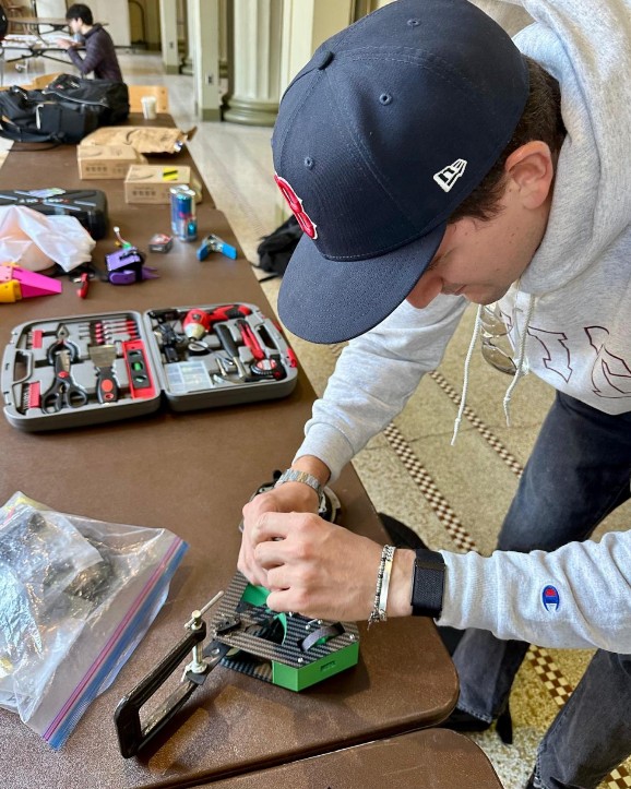
So I redesign a bearing mount part as well as a top holder, and launch a PLA print.
I put everything together again, test it in the box and.. it seems to be working. IT IS WORKING!
It's late night, the competition starts in less than 8 hours, but I am ready!

Saturday, November 15
Location
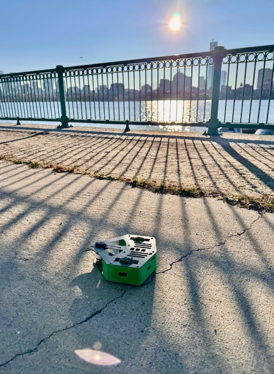
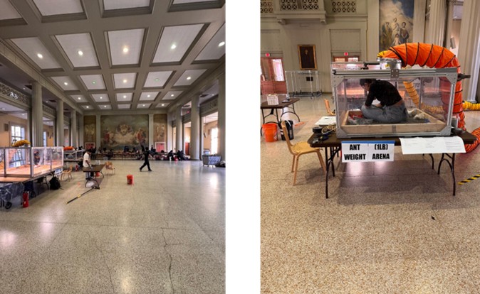
It’s Saturday, November 15th, 2025, and the competition is being held at Walker Memorial (MIT Building 50), 142 Memorial Drive, Cambridge. Drivers are expected to arrive by 8 a.m., so before heading in, I stop by the river to take a nice photo of Trallallero.
When I get in, the CRC club is still finishing the setup. There’s a lot to do, and they’ve put in an incredible amount of work to make this event happen. Huge shoutout to the entire CRC club for making this possible. The venue looks amazing, with two cages ready - one for the Antweight category and one for the Beetleweight category.
Agenda for the day
|
Time |
Activity |
|
8 – 9:45 am |
Builder check in, pit load in, robot safety inspections |
|
9:45 – 10 am |
MANDATORY Competitors meeting |
|
10 am – 1 pm |
Fights |
|
1 pm – 2 pm |
Break for lunch |
|
2 pm – 6:30 pm |
Fights |
|
6:30 – 7 pm |
Awards ceremony |
|
7 – 8 pm |
Load out |
Rules
Here some of the rules sent out by the organizers about this specific event
Robot Construction
Robots should be built in compliance with the SPARC Ruleset, noting modified weight bonuses specified below. The event has additional restrictions on the robots eligible for our competition, which are listed below:
- NO heat/combustion based weapons (fire, flamethrower, soldering iron, explosives)
- NO hammersaws/hammer spinners/hammers
- NO pneumatics
The ban on overhead weapons is due to EHS mandating a LiPo fire will result in the end of the event.
Weight Bonuses
The following weight bonuses will be employed:
- Shuffler = 1.25x
- NTL (No Translational Locomotion) = 1.5x
- True walker = 2x
- Multibot = 1.5x (Max segment weight = [total weight allowance]/[number of segments])
Robot Safety
Every robot must pass a safety inspection before entering the tournament. Must demonstrate:
- Controlled movement (robot only moves when driver inputs commands).
- Active weapon lock (weapon cannot actuate, rotate, extend, or move).
- Failsafe mechanism (robot and weapon must stop after signal loss).
While in the pits:
- Weapon lock must always be installed unless working directly on the weapon.
- Weapon testing in the pits is strictly forbidden.
- For weapon testing, an organizer must escort you to the test box.
Match Structure
Format:
- Each match lasts 3 minutes.
- Each robot is allowed one unstick per match (either from the arena or from robot entanglement).
- If both robots become entangled, the referee pauses the match and separates them.
Ways a Match Can End
- Tap Out (TO)
- A driver may forfeit by shouting “Tap Out!” repeatedly
- Once acknowledged by the referee, the match ends and the opponent wins
- Knock Out (KO)
- If a robot cannot move for 5 seconds, the referee begins a 10-second countdown.
- To cancel the countdown, the robot must show controlled movement (e.g., crab-walking).
- If it cannot regain movement by the end of the countdown, the opponent wins.
- Double Knockout (DKO)
- If both robots are immobile for 5 seconds, a simultaneous 10-second countdown
- If neither robot shows controlled movement before the countdown ends → match goes to Judge’s Decision (JD).
- If one robot regains movement → countdown stops, and KO procedure resumes for the other robot.
- Judge’s Decision (JD)
- If no Tap Out or Knock Out occurs by the end of 3 minutes, judges determine the winner.
- Judging is based on Damage, Control, Aggression
Registration
efore officially entering the tournament, all robots must be weighed to confirm they meet the competition’s limits. There are no scale differences allowed—any robot above its class limit is sent back to the pits to make adjustments.
So I head to the registration desk for the weigh-in. The limit is 1.00 lb, and Trallallero comes in at an official weight of…
“Niiiiine–point–eight–eight ounces of pure spinning fury… TRALLALLEROOOO!”
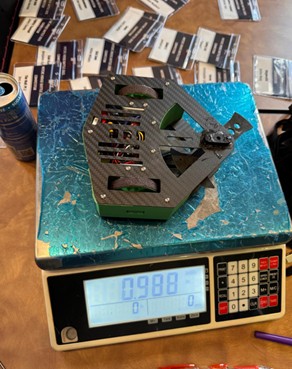
Having done that, I am now officially in!

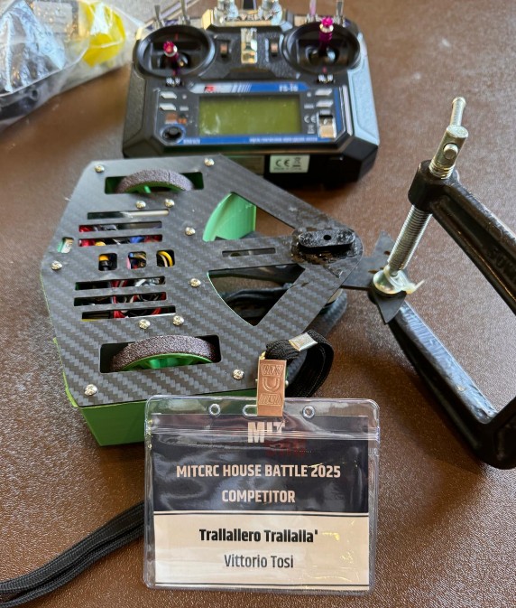
I head over to the pits, and this is my setup:
Official Shooting😎
Before everything starts, there is a photographer taking professional pictures. As now I am an official athlete in combat robotics (hehe) I head over to have some shots taken.
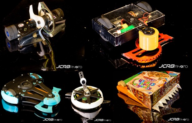
And here some pictures of other nice bots in the event (credits to JCRBPhoto)
Definitely, getting to know the different teams in the pits was super exciting.

Testing
Before the actual fight, I need to demonstrate that the bot actually works, and it can do so safely. So I do that.
Time to fight
Round 1
My first fight is scheduled between 10 and 11 a.m., and I’m both excited and a bit anxious. When I’m called up, I place Trallallero in the arena and wait for the opponent.
And… there is no opponent. It’s unclear what happened—maybe issues at weigh-in, maybe a technical failure, or maybe they never showed up at all. Either way, Trallallero advances straight to Round 2!
Round 2
Unfortunately, this is where my luck runs out. Out of roughly 30 robots in the bracket, I get paired with a bulky horizontal spinner. I was hoping for a ram or a lifter - something without a real weapon - but instead my opponent has both a name and a reputation: Martial Law. A tough matchup for a little guy named Trallallero.
This is what my opponent looks like. The design is similar to mine, but the overall footprint is smaller because they invested their weight differently: thicker carbon fiber, heavier wheels, and a beefier frame. What does that mean?
- They will likely drive better than me.
- They can probably take hits more effectively.
- But their weapon diameter is shorter, and their blade is lower than mine.
So if we meet head-on, it won’t be a weapon-on-weapon exchange. My blade should strike first. I think about it, and I come up with a simple strategy: go straight at them.
Here how it went:
YES — Trallallero Trallallà won a clean, fair fight against a very tough opponent with a 3–0 judge’s decision!! I genuinely didn’t expect this. I delivered on the goal I set for myself, and everything beyond this point is just bonus happiness.
After the fight, I went to the pits to inspect the damage. And my strategy clearly worked. Thanks to my longer weapon reach, I was able to hit their motor directly - because they mounted it upside down - and it got completely destroyed.
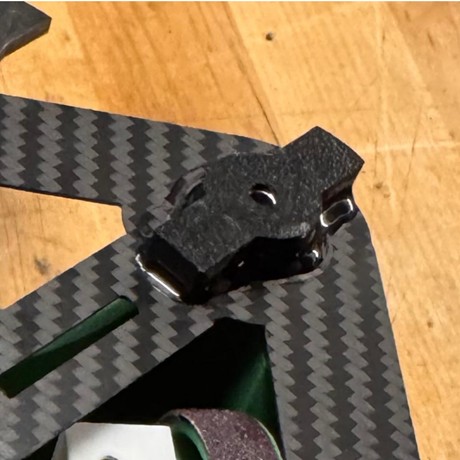
Round 3
I may have won the battle, but returning to the pits made it clear I was losing the war. Trallallero was damaged - not so much by the opponent, but mostly by itself. The bearing mechanism that was giving me trouble the night before finally failed. Somehow, the ball bearing holding the motor shaft shifted and fused vertically, instead of sitting horizontally in the PLA mount.
Between fights you only get about 20–30 minutes to repair your bot. I did have a spare bearing mechanism, but everything is superglued to the carbon fiber plate, and I only have one of those. That means I have to salvage the existing setup.
With a heat gun, I manage to push the bearing back into a horizontal position, but I’m worried I may have warped it and knocked things off-axis.
I don’t have much time, but here a picture of me trying to follow Neil's words: "Have you documented it?"
There’s no time to test. I just have to grab the bot and head straight into the cage.
This time, I’m paired against a vertical spinner, which is just about the worst matchup for me. With my weapon already unstable, a direct weapon-on-weapon clash would almost certainly end in disaster. So the strategy flips completely:
- Avoid head-on engagements
- Look for openings on their sides
- Rely on driving, not weapon exchanges
I get into the cage, and after nearly two minutes of trading hits and trying to stay clear of their weapon, the thing I feared most finally happens: a direct weapon clash. My shaft pops out of the ball bearing, and before I can shut the motor down, the bottom plate snaps as the weapon spins off-axis. At that point, I have no choice - I have to tap out.
I don’t have footage of the fight itself, but a bystander did manage to snap a photo of me afterward. I was definitely still smiling: pretty happy, even knowing I’d probably been torn apart.
Round 4 (Losers bracket)
I lost this fight, but technically I’m still in the tournament. It’s a double-elimination format, so everyone is guaranteed two matches—you drop into the losers bracket after the first loss.
In practice, though, it’s unlikely I can continue. The bottom plate is broken and, once again, I only have one. On top of that, the drive system feels impaired and I’m not sure why.
I’ve got just 20–30 minutes and no spare parts. But you know what? I do have the PLA bottom plate I used earlier just for dimension testing. Would that work well? Probably not - PLA won’t hold a motor in place, especially with the top bearing still damaged. So why even try?
My answer: Why not? I’ve made it this far, and there’s no reason not to push it to the limit. Trallallero is a fierce little warrior and deserves to go out fighting. Let’s do this.
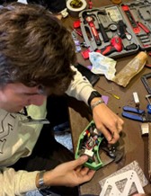
It’s… more or less ready (definitely more less than more), and I get called up. Unfortunately, my next opponent is another vertical spinner - the only one in the losers bracket. Tough luck.
Strategy stays the same: avoid weapon exchanges at all costs. And given how fragile the bottom plate is, I decide not to spin the weapon above 30% power.
The fight is short. I enter the cage, the match begins, I try to stay mobile and avoid hits… and the moment I ramp the weapon up to about 20–30%, it immediately vibrates itself apart and shatters the PLA plate - without even getting hit. Tap out.
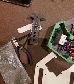
Trallallero tournament ends here, with 2W and 2Ls.
Winner
I stayed to watch the rest of the tournament play out. And in case you’re curious, here’s the robot that actually won:
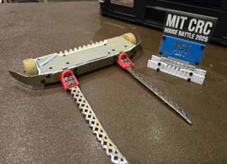
This is Harley Queen, a very well-known and respected bot in the combat robotics community. As you can see, it doesn’t use a traditional damaging weapon - it's a lifter. Its entire strategy is built around scoring control (and aggression) rather than damage.
Those metal forks slide underneath the opponent, and with a quick rotation, the bot lifts them off the ground. Once the opponent’s wheels are in the air, they’re immobilized. Harley Queen holds them there for the allowed 10 seconds, backs away, circles around, and repeats.
The whole strategy is clearly reflected in its design:
- Super fast drive: The robot is noticeably quicker than most others, and the driver clearly has a lot of experience maneuvering it with precision.
- Extremely low profile: The bot sits very low—lower than the weapon motors of most horizontal spinners in this weight class. For bots like Trallallero, this would be a terrible matchup: almost impossible to land a solid hit.
The end
And just like that, the best day of this semester comes to an end. Trallallero Trallalla' is finally a pro fighther, currently ranked 367 in the world (according to robotcombatevents.com). Not bad for a tiny spinner held together by hope, superglue, and questionable engineering decisions!
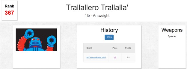
Week 12: Documenting, reflecting, and planning (again) with purpose
This week marks a shift in pace and intention. After the excitement (and chaos) of the competition, I decided to take a moment to catch some air and not to advance much on the physical robot itself. Instead, Week 12 is about taking a step back, documenting everything thoroughly (all the above has been revised in this week 😊), and thinking about what comes next.
Building my first combat robot was an incredible learning experience, one that gave me a much deeper understanding of the craft, of the design choices that matter, and of the mistakes that only reveal themselves through real battles. This chapter is where I begin shaping the future direction of Trallallero.
I started the week by reflecting on everything I learned from creating and fighting my first bot. These insights now form the foundation for the next version (will 2026 be the year of Trallallero Trallalla' 2.0?), which I want to have ready by mid-March for another competition. Some of the most important learnings include:
- Thicker carbon fiber is essential for structural integrity, especially for absorbing impacts from horizontal and (mostly) vertical spinners.
- A stronger, more reliable shaft-holding mechanism is needed: my bearing mount was the weakest link in the entire design.
- A lower-profile robot would help save weight and allow me to engage opponents’ lower weapon motors more effectively.
- Larger wheels could improve traction and overall drivability.
- Need spares too to bring at the competition.
These changes will likely push me toward a smaller, denser robot, but I still want to maintain a large weapon diameter if I stick with a horizontal spinner design.
Going forward, I will use these learnings as the foundation for the next phase - but I won’t begin building “Trallallero 2.0” just yet. Instead, from now until mid-December, I will focus on creating a new version of the robot specifically for class, one that intentionally incorporates as many techniques as possible from the course. In parallel, I will use this experience to prepare the more competitive iteration I aim to debut in March.
Below are the main areas I plan to address in the remaining weeks:
- Reprinting all the parts , so basically building a new Bot.
- Designing my own PCB to replace the commercial receiver, integrating the logic needed to control the ESCs for both the drive motors and the weapon motor.
- Building a Wi-Fi control system, so I can operate the robot from my laptop. This means designing the PCB to interface with the appropriate microcontroller.
- Experimenting with wheel design, potentially casting custom wheels - this is still TBD, but it’s an exciting direction.
- (TBD) Creating custom vinyl stickers to give the robot a more intentional, polished identity.
- (TBD) Printing the TPU spike walls I had originally envisioned, improving both style and functionality.
These are the pillars that will guide the development from now until mid-December. It will not be a robot designed to compete (will likely be above 1lb, for example), but will reflect a broad range of fabrication techniques I’ve learned.
Week 13 – From Keyboard to Motors (somehow)
This week I focused on designing a PCB to replace the commercial receiver I used during the November battle. I have well documented that process in the corresponding week 13 page, so here I will provide a summary.
I designed a custom PCB around the XIAO ESP32-S3, which serves as the robot’s communication and motor-control processor. The board includes a 5 V regulator to safely power the microcontroller from the 3S LiPo battery, protective components, and pin headers for the dual drive ESC and the weapon ESC.
On the software side, I first validated the hardware by writing a simple PWM-control script and sending commands over Serial. This let me confirm that the ESCs armed correctly, that the GPIO pin mapping was right, and that both motors responded to 1000–2000 µs pulse values.
Once this worked, I built a Python controller that captures keyboard inputs (arrow keys), computes differential-drive values, applies acceleration smoothing, and sends the resulting left/right values to the board. This became my first fully functional driving interface.
From there, I moved to full wireless control. I programmed the ESP32-S3 to broadcast a custom Wi-Fi network and run a TCP server. My Python app now connects to that network and streams motor commands directly over Wi-Fi. The ESP32-S3 decodes these values and generates the appropriate PWM signals for each ESC. This completely removes the USB tether and turns the system into the robot’s dedicated wireless receiver.
Week 14 – (Re)Printing and (Re)Assembling everything
As mentioned earlier, this is not Trallallero 2.0 yet. However, I’m lifting the weight constraints, reprinting the parts that were damaged, and making some aesthetic improvements. Below are a few of the items discussed this week. The goal is to have Trallallero ready by Monday the 16th for the final presentation.
Reprinting walls
For the walls, I decided to lean into a bit of extravagance and experimentation. I ran a mixed print, manually changing the filament halfway through the job so the walls alternate between white and green. This approach worked well: the parts came out clean, consistent, and visually striking, giving the robot a more intentional and polished appearance rather than a purely functional one.
With regard to material used, since this version is being printed for class rather than for an actual battle, I decided to switch to standard PLA and allow myself to be a bit more extravagant. The walls are printed in standard PLA (not SuperPLA). While this material offers slightly lower impact resistance, it is much faster and easier to print and reprint, which is a deliberate tradeoff at this stage.
Printing TPU spikes
It was time to finally make some spikes. I printed them in TPU to take advantage of its flexibility and impact resistance, which makes the spikes more durable and less prone to snapping compared to rigid plastics. Printing in TPU required different settings than PLA - lower print speeds, reduced retraction, and more controlled extrusion - to account for the material’s elasticity. Luckily, Gert provided a file with such parameters already set up. The parts came out clean and well-defined, with only minor spider-web stringing, which is typical for TPU and easy to clean up.
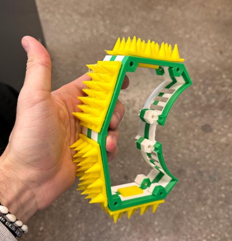
Casting Wheels
Since weight is no longer a constraint, I decided to also cast custom wheels rather than relying on off-the-shelf parts. I designed and fabricated a 4-part mold and cast the wheels using Smooth-On SORTA-Clear 37, a transparent, platinum-cure silicone rubber with Shore A 37 hardness. This material is tough, flexible, and tear-resistant, making it well suited for wheels that need compliance, grip, and durability while still allowing visual inspection of the internal features.
A key challenge with silicone wheels is that silicone does not adhere well to plastics, so mechanical retention becomes critical. To address this, I explicitly designed retaining features into the wheel core to ensure the silicone locks in place under load and torque. I explored four different retention strategies:
- T-slots, to provide strong mechanical undercuts
- Loops, to create continuous anchoring paths through the silicone
- Gyroid interface at 10% infill, offering a lightweight, compliant interlock
- Gyroid interface at 20% infill, increasing stiffness and mechanical engagement
The gyroid interfaces were created by modeling a hollow tube with an inner diameter 2–3 mm smaller than the wheel, an outer diameter 3–4 mm larger than the wheel, and the same height as the wheel. This tube was overlapped with the wheel model directly in the slicer and set to gyroid infill at either 10% or 20%, with 0 perimeters, 0 top and bottom layers, and 0 infill anchors. This produces a porous, three-dimensional lattice that the silicone can flow into and mechanically lock around once cured.
Because the mold was split into four parts, demolding was straightforward and low-risk, even with complex internal geometry. The wheels released cleanly, preserving both surface quality and the integrity of the internal retaining features.
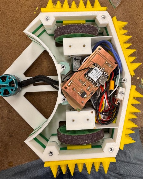
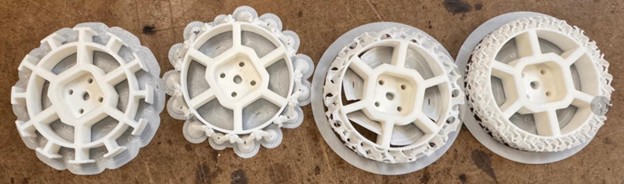
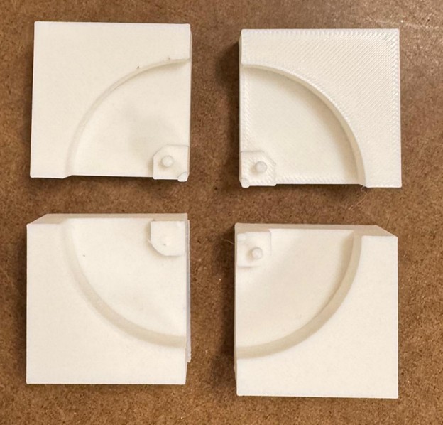
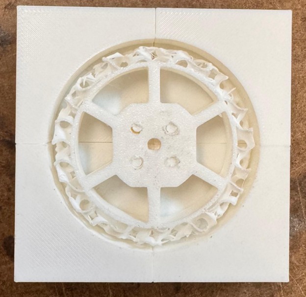
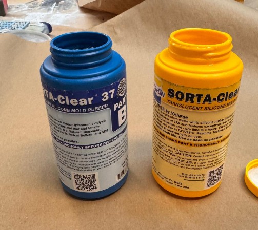
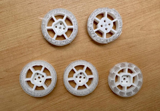
Creating a mount for the PCB
Since I designed and assembled a custom PCB, it was important to avoid leaving it floating loose inside the robot, which would be unsafe and significantly increase the risk of mechanical damage, short circuits, or connector failure during handling and operation. A stable and constrained mounting solution was therefore necessary.
The PCB includes four mounting holes at the corners, which I leveraged to design a dedicated PCB mount. This mount allows the board to be slotted securely into place, constraining it in all directions and preventing vibration or movement. The mount is integrated onto the bottom plate of the robot, keeping the PCB low, protected, and mechanically grounded to the chassis.
In addition, I included an access hole aligned with the PCB’s USB port. This allows me to plug in a USB cable directly and connect the board to a laptop for debugging, flashing, or code updates without having to disassemble or demount the entire robot.
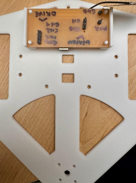
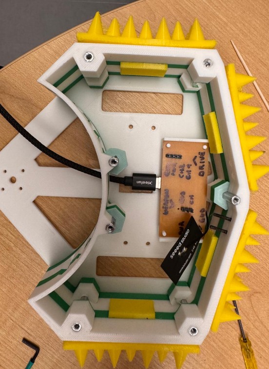
Creating custom stickers
Since this build is no longer just for combat, I wanted it to look intentional and finished. I designed a custom sticker for Trallallero Trallallà, inspired directly by the spinning weapon geometry. I created the design as a PNG, cut it in red vinyl using the vinyl cutter, and applied it to the top of the robot to improve visibility and overall appearance.

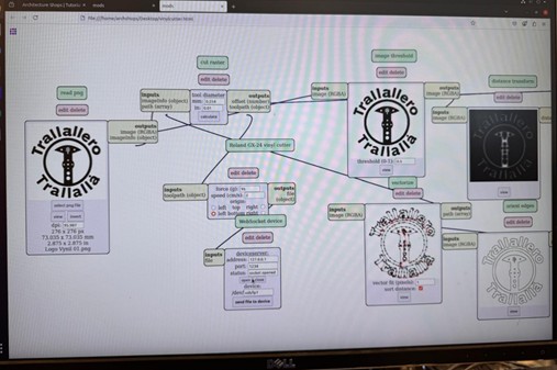
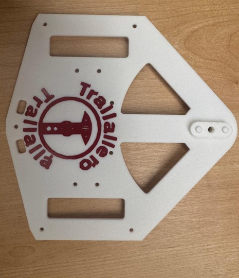
Revisiting Connectivity
By this point in the project, I had already achieved full laptop-based control of the robot. On the robot side, the Arduino firmware running on the ESP32-S3 is responsible for translating incoming numeric commands into standard RC-style PWM signals. These signals are sent directly to the drive ESC and the weapon ESC. By varying the pulse width at a fixed 50 Hz frequency, the firmware controls both motor speed and direction for the drivetrain and the weapon. At this stage, the electronics, power distribution, and motor control logic had already been validated and were working reliably.
On the control side, all user interaction happens on the laptop through a Python application. Python reads user inputs, converts them into structured control values, and sends them to the robot over Wi-Fi. Initially, this interface was keyboard-based: arrow keys controlled driving, while additional keys were used to spin up, slow down, or stop the weapon. This setup was extremely useful for early testing and debugging, but it quickly showed its limits. Keyboard input is binary and abrupt, whereas a combat robot benefits greatly from smooth, proportional control.
On the control side, the robot was driven entirely from a Python script running on my laptop. Python handled user input and sent structured control values to the robot over the network. Initially, inputs came from the keyboard: the program read left, right, up, and down arrow keys to drive the robot, and additional letter keys to control functions such as weapon spin-up and stop. This setup worked well for testing and debugging, but it was awkward and imprecise for real driving.
To improve this, I moved to a game controller, specifically a PS5 controller, to enable analog input. The first idea was to connect the controller directly to the robot via Bluetooth. This approach failed: I discovered how Bluetooth works and the ESP32-S3 primarily supports Bluetooth Low Energy (BLE), while the PS5 controller relies on Bluetooth Classic (BR/EDR). So I could not integrate those.
The final and much cleaner solution was to keep the controller on the laptop and use the laptop as an intermediary. The PS5 controller connects to the laptop using full Bluetooth Classic support, where Python, through a mature input library, handles joystick axes, button presses, dead zones, debouncing, and reconnection reliably. The Python application then sends clean, rate-limited numeric commands over Wi-Fi to the robot. On the robot side, nothing fundamentally changed: the Arduino firmware continues to receive the same command format and convert it into PWM outputs for the ESCs. This separation keeps the embedded code simple and isolates safety-critical motor control from higher-level input handling.
The final Python control program performs several key tasks:
- Reads analog joystick inputs and maps them to differential drive commands with configurable speed limits and turning sensitivity.
- Implements multiple driving modes (turtle, normal, insane), ranging from slow and precise to aggressive, switchable in real time.
- Controls the weapon using incremental “nudges” rather than absolute stick position, preventing accidental spin-up when the controller is idle.
- Applies acceleration ramping to both drive and weapon commands to avoid sudden changes that could destabilize the robot.
- Supports an upside-down driving mode, allowing the robot to remain controllable if flipped during combat.
- Provides emergency stop and safe shutdown commands that immediately zero all outputs.
In the final control mapping:
- Right analog stick controls driving (forward/backward and turning via differential drive).
- Left analog stick (Y-axis) incrementally increases or decreases weapon speed.
- X button steps up through driving modes.
- Square button steps down through driving modes.
- Circle button performs an immediate stop and resets to the safest driving mode while staying connected.
- Triangle button performs a full stop and disconnects.
- Keyboard up/down arrows toggle between normal and upside-down driving orientation.
Full Code
import time
import socket
import pygame
from pynput import keyboard

# ====== CONFIG ======
HOST = "192.168.4.1"   # ESP32 AP IP
PORT = 4210            # must match TCP_PORT in your firmware

RAMP_RATE_DRIVE = 5    # how fast drive changes per tick
RAMP_RATE_WEAPON = 2   # how fast weapon changes per tick
UPDATE_DT = 0.05       # loop period (seconds)

DEADZONE = 0.15        # ignore tiny stick movements

# ---- DRIVING MODES ----
# mode 1: slow, gentle turning
# mode 2: normal
# mode 3: max crazy
DRIVE_MODES = [
    {"name": "Mode 1 – Turtle",     "max_speed": 30,  "turn_strength": 10},
    {"name": "Mode 2 – Normal",     "max_speed": 60,  "turn_strength": 20},
    {"name": "Mode 3 – Aggressive", "max_speed": 100, "turn_strength": 60},
]

# ---- AXIS / BUTTON MAPPING ----
# Typical DualSense mapping in pygame (may vary slightly by system):
#   axis 0: left stick X
#   axis 1: left stick Y
#   axis 2: right stick X
#   axis 3: right stick Y
AXIS_RX = 2      # right stick X (turn)
AXIS_RY = 3      # right stick Y (forward/back)
AXIS_LY = 1      # left stick Y (weapon "nudge" control)

# Buttons (typical): X=0, O=1, Square=2, Triangle=3
BUTTON_X = 0         # X -> mode up
BUTTON_O = 1         # O -> stop, stay connected, reset to mode 1
BUTTON_SQUARE = 2    # Square -> mode down
BUTTON_TRIANGLE = 3  # Triangle -> stop + disconnect, reset to mode 1

# How much weapon setpoint changes per tick when you push the left stick
WEAPON_STEP = 5    # 5 units per 50 ms -> full range in ~1 second if held
# ====================


def ramp(value, target, rate):
    """Move value toward target by at most `rate` per step."""
    if value < target:
        return min(value + rate, target)
    elif value > target:
        return max(value - rate, target)
    return value


def apply_mode(mode_index):
    mode = DRIVE_MODES[mode_index]
    print(f">>> Driving mode: {mode['name']} "
          f"(speed={mode['max_speed']}, turn={mode['turn_strength']})")
    return mode["max_speed"], mode["turn_strength"]


def main():
    # ----- Connect to robot over TCP -----
    print(f"Connecting to {HOST}:{PORT} ...")
    sock = socket.socket(socket.AF_INET, socket.SOCK_STREAM)
    sock.settimeout(5.0)
    sock.connect((HOST, PORT))
    sock.settimeout(None)
    print("Connected to robot.\n")

    # ----- Init pygame + joystick -----
    pygame.init()
    pygame.joystick.init()

    if pygame.joystick.get_count() == 0:
        print("No gamepad detected. Pair the PS5 controller and try again.")
        return

    js = pygame.joystick.Joystick(0)
    js.init()
    print(f"Using controller: {js.get_name()}")
    print("Controls:")
    print("  Right stick: drive (forward/back on Y, turn on X)")
    print("  Left stick (Y): weapon power nudge (up = more, down = less)")
    print("  Keyboard DOWN arrow: switch to UPSIDE-DOWN driving mode (invert drive)")
    print("  Keyboard UP arrow: back to NORMAL driving mode")
    print("  X: mode UP (1 → 2 → 3)")
    print("  Square: mode DOWN (3 → 2 → 1)")
    print("  O: STOP (0 0 0) + reset to Mode 1 (stay connected)")
    print("  Triangle: STOP (0 0 0) + reset to Mode 1 + disconnect + exit")
    print("Ctrl+C in this window to quit.\n")

    # ---- Driving mode state ----
    current_mode_index = 0  # START IN MODE 1
    MAX_SPEED, TURN_STRENGTH = apply_mode(current_mode_index)

    # debounce for X / Square
    prev_x = False
    prev_square = False

    # ---- Orientation state ----
    upside_down = False  # starts normal

    def set_orientation(new_state: bool):
        nonlocal upside_down
        if upside_down != new_state:
            upside_down = new_state
            if upside_down:
                print(">>> Orientation: UPSIDE-DOWN mode (drive inverted)")
            else:
                print(">>> Orientation: NORMAL mode")

    # ---- Keyboard listener for Up/Down arrows (orientation toggle) ----
    key_state = {"up": False, "down": False}

    def on_press(key):
        if key == keyboard.Key.up:
            if not key_state["up"]:
                key_state["up"] = True
                set_orientation(False)  # normal
        elif key == keyboard.Key.down:
            if not key_state["down"]:
                key_state["down"] = True
                set_orientation(True)   # upside-down

    def on_release(key):
        if key == keyboard.Key.up:
            key_state["up"] = False
        elif key == keyboard.Key.down:
            key_state["down"] = False

    listener = keyboard.Listener(on_press=on_press, on_release=on_release)
    listener.start()

    current_left = 0.0
    current_right = 0.0
    current_weapon = 0.0

    # Target drive and weapon values (what we *want* to reach)
    target_left = 0.0
    target_right = 0.0
    weapon_target = 0.0  # 0..100, starts at 0 and only changes when you nudge

    last_left = None
    last_right = None
    last_weapon = None

    try:
        while True:
            # Process pygame events to keep joystick state updated
            for event in pygame.event.get():
                if event.type == pygame.QUIT:
                    raise KeyboardInterrupt

            num_buttons = js.get_numbuttons()

            # ---- Mode switching with X / Square (edge-detected) ----
            x_now = num_buttons > BUTTON_X and js.get_button(BUTTON_X)
            square_now = num_buttons > BUTTON_SQUARE and js.get_button(BUTTON_SQUARE)

            # X: mode up (1->2->3, stays at 3)
            if x_now and not prev_x:
                if current_mode_index < len(DRIVE_MODES) - 1:
                    current_mode_index += 1
                    MAX_SPEED, TURN_STRENGTH = apply_mode(current_mode_index)

            # Square: mode down (3->2->1, stays at 1)
            if square_now and not prev_square:
                if current_mode_index > 0:
                    current_mode_index -= 1
                    MAX_SPEED, TURN_STRENGTH = apply_mode(current_mode_index)

            prev_x = x_now
            prev_square = square_now

            # ---- STOP buttons ----
            # O: hard stop, stay connected, reset to mode 1
            if num_buttons > BUTTON_O and js.get_button(BUTTON_O):
                target_left = target_right = 0.0
                weapon_target = 0.0
                current_left = current_right = current_weapon = 0.0

                current_mode_index = 0
                MAX_SPEED, TURN_STRENGTH = apply_mode(current_mode_index)
                set_orientation(False)  # back to normal orientation

                msg = "0 0 0\n"
                sock.sendall(msg.encode("ascii"))
                print("O pressed -> STOP + reset to Mode 1:", msg.strip())

                time.sleep(0.2)  # debounce while holding button
                continue

            # Triangle: stop + disconnect, reset to mode 1
            if num_buttons > BUTTON_TRIANGLE and js.get_button(BUTTON_TRIANGLE):
                current_mode_index = 0
                MAX_SPEED, TURN_STRENGTH = apply_mode(current_mode_index)
                set_orientation(False)  # back to normal orientation

                msg = "0 0 0\n"
                try:
                    sock.sendall(msg.encode("ascii"))
                except Exception:
                    pass
                print("Triangle pressed -> STOP + reset to Mode 1 + disconnect:",
                      msg.strip())
                break

            # --- Read axes for drive (right stick) ---
            rx = js.get_axis(AXIS_RX)  # -1..1
            ry = js.get_axis(AXIS_RY)  # -1..1

            if abs(rx) < DEADZONE:
                rx = 0.0
            if abs(ry) < DEADZONE:
                ry = 0.0

            # ry: up=-1, down=+1 -> invert so up=forward
            throttle = -ry * MAX_SPEED
            turn = rx * TURN_STRENGTH

            target_left = throttle - turn
            target_right = throttle + turn

            # Clamp to [-100, 100]
            target_left = max(-100, min(100, target_left))
            target_right = max(-100, min(100, target_right))

            # If flipped, invert both wheels so controls feel the same
            if upside_down:
                target_left = -target_left
                target_right = -target_right

            # --- Weapon control with left stick Y as "nudge" ---
            ly = js.get_axis(AXIS_LY)  # -1..1
            if ly < -DEADZONE:
                weapon_target += WEAPON_STEP
            elif ly > DEADZONE:
                weapon_target -= WEAPON_STEP

            weapon_target = max(0.0, min(100.0, weapon_target))

            # --- Ramping for smoothness ---
            current_left = ramp(current_left, target_left, RAMP_RATE_DRIVE)
            current_right = ramp(current_right, target_right, RAMP_RATE_DRIVE)
            current_weapon = ramp(current_weapon, weapon_target, RAMP_RATE_WEAPON)

            # --- Only send if changed ---
            if (int(current_left) != int(last_left or 999) or
                int(current_right) != int(last_right or 999) or
                int(current_weapon) != int(last_weapon or 999)):

                l = int(current_left)
                r = int(current_right)
                w = int(current_weapon)

                msg = f"{l} {r} {w}\n"
                try:
                    sock.sendall(msg.encode("ascii"))
                except Exception:
                    print("Error sending to robot, disconnecting.")
                    break

                print("Sent:", msg.strip())
                last_left = current_left
                last_right = current_right
                last_weapon = current_weapon

            time.sleep(UPDATE_DT)

    except KeyboardInterrupt:
        print("\nKeyboardInterrupt -> stopping and disconnecting...")
        try:
            sock.sendall(b"0 0 0\n")
        except Exception:
            pass
    finally:
        try:
            # Always try to stop robot before exiting
            try:
                sock.sendall(b"0 0 0\n")
            except Exception:
                pass
            sock.close()
        except Exception:
            pass

        try:
            listener.stop()
        except Exception:
            pass

        pygame.joystick.quit()
        pygame.quit()
        print("Done (socket closed).")


if __name__ == "__main__":
    main()
Re-testing the real weapon (mostly for fun)
For this robot, I originally designed and waterjetted a weapon made from hardened steel, intended to be the real, battle-ready spinner. The weapon is designed to spin extremely fast, reaching speeds that make it genuinely dangerous: at full RPM, it could easily snap a finger or seriously injure someone if operated outside of a controlled environment.
After consulting H&S, I was explicitly prohibited from spinning this weapon outside of a certified safety cage. I made attempts to source or borrow a cage by reaching out to different people and groups, but this was not possible. Given the weapon’s speed and mass, spinning it in the open would be completely unsafe and irresponsible… unfortunately I cannot do much about this.
Before settling on a solution that I could safely demonstrate in class, I decided to retest the steel weapon under controlled conditions. To do so, I ran a series of impact tests against the following objects:
- Bell pepper
2. Apple
3. Toilet paper roll
4. Beer can (empty, obviously)
5. Book
The corresponding videos are shown below.
Unfortunately, after the toilet paper roll test, building administration intervened and asked me to stop the experiment. Despite my attempts to explain the critical importance of proper documentation for HTMAA, I was unable to persuade them. As a result, I had to clean up the area and discontinue testing.
ROUND I: Bell Pepper
ROUND II: Apple

ROUND III: Toilet Paper
Creating a Safe Weapon for Class Demonstration
However, for class purposes, I still wanted to demonstrate how fast the weapon system spins. To do this safely, I created a soft, non-hazardous weapon. I replicated the geometry of the original weapon and cut it out of a kitchen sponge.
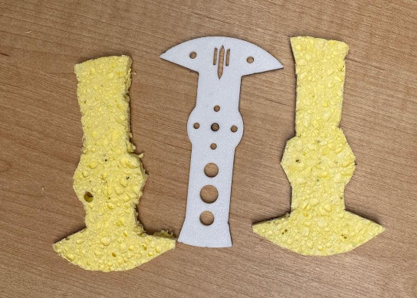
Final assembly
Here videos of (re)putting everything together for class presentation.
Assembling Walls
Press-fitting Standoffs
Putting PCB in place
Mounting the walls to the bottom plate
Putting wheel motors into motor mounts
Screwing wheels to wheel hubs
Testing switch and battery, and connecting
Testing the weapon
Testing Turtle driving mode
Testing Normal driving mode
Testing Insane driving mode
Week 14 – Where (hopefully) everything comes together
Key questions
What does it do?
- A 1 lb (antweight) horizontal spinner combat robot named Trallallero Trallallà’.
- Designed to drive (2WD) and spin an AR500 steel weapon at high RPM to inflict damage in an arena.
- Built to be competition-ready: fully functional, under the 1 lb limit, driven remotely.
- Successfully fought at the MIT combat robotics House Battle (Nov 15, 2025), reaching quarter finals.
- Rebuilt for class presentation lifting the 1lb weight constraint and using additional digital fabrication techniques.
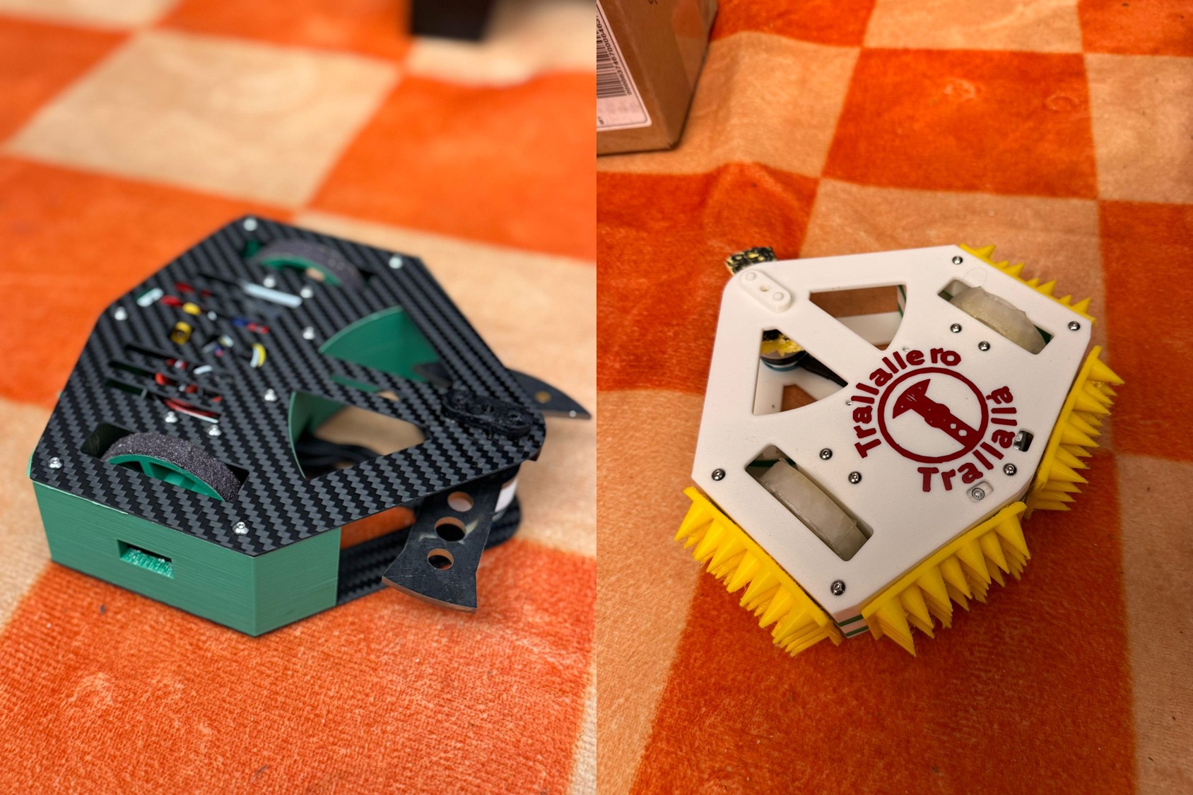
Who’s done what beforehand?
- Combat robotics is an established competitive sport, with well-defined rules, weight classes, and design norms.
- Within this ecosystem, many bot archetypes exist (spinners, wedges, control bots, flippers, etc.). For this project, weapon layout, balance solutions, and combat strategy were specifically inspired by successful antweight horizontal spinners such as Cheesecake and Tiramisu.
What sources did you use?
- Broad initial exploration of combat robotics: since this discipline was new to me, I invested significant time in understanding the ecosystem through online resources, including Discord communities, YouTube channels, forum discussions, and multiple antweight build guides.
- MIT Combat Robotics Club (CRC): after the initial exploration, I connected with the CRC, which provided deep practical knowledge of the sport, hands-on guidance, access to maker spaces.
- NHRL (National Havoc Robot League) official pages: used as a reference for rules, competition standards, and judging frameworks, ensuring the robot was designed in line with established competitive norms.
What did you design?
- Two distinct versions of the robot, serving different purposes:
- A competition-ready robot that successfully fought on November 15
- A presentation-ready robot, intended as a polished showcase of the project for December 15.
- For the competition-ready robot, I designed in Fusion 360 all key mechanical components, including:
- Chassis system: top plate, bottom plate, structural walls.
- Weapon system: spinner geometry, weapon mount, and bearing interface.
- Drive system: wheels, motor mounts, and hubs
- In parallel, I designed a presentation-focused version of the robot, which included:
- A custom PCB for cleaner and more intentional electronics integration.
- Custom cast wheels, replacing purely printed parts.
- Vinyl stickers and visual detailing, giving the robot a finished, exhibition-quality appearance.
- The design went through multiple CAD iterations to achieve:
- Weight reduction while preserving stiffness and impact resistance.
- Fast assembly and disassembly for repairs between fights.
What materials and components were used?
- Normal PLA in White and Green for prototyping and non-critical parts
- Overture Super PLA in Green for walls
- TPU in Yellow for Armor Spikes
- Carbon fiber sheets (1 mm and 2 mm) for top and bottom plates
- AR500 steel (1/8") for the weapon
- Electronics
- XIAO ESP32-S3
- 3S 380 mAh LiPo battery
- Brushless direct-drive weapon motor
- Two brushed drive motors
- Dual brushed drive ESC
- Brushless weapon ESC
- FlySky receiver (later replaced by PCB)
- Mechanical power switch
- PS5 controller
- Hardware
- Bearings, standoffs, screws, nuts, hubs
Where did they come from?
- Repeat Robotics: motors, ESCs, receiver, switch
- Pyrodrone: battery
- Amazon: carbon fiber sheets
- Facebook Marketplace: PS5 controller
- McMaster-Carr: hardware and bearings
- MITERS: AR500 steel stock
- Other Electronics: Architecture Shop
How much did they cost?
- Electronics & core components
- Battery: $11.99
- Weapon motor: $20
- Drive motors: $40
- Drive ESC: $15
- Weapon ESC: $13.50
- Receiver: $13
- Switch: $10
- Subtotal: $123.49
- Hardware
- Standoffs: $17.40
- Screws, nuts, hex keys: $23.72
- Bearings: $22.28
- Carbon Fiber: $60
- Subtotal: $123.40
- Total cost: $246.89
- Filament, consumables, PS5 controller, PCB components, and AR500 steel not fully itemized
What parts and systems were made?
- All the parts have been manufactured (chassis walls, wheels, motor mounts, bearing holder, weapon mount, weapon, PCB,…), with the exception of motors, ESCs, controllers, and hardware parts (i.e., screws, standoffs, etc.)
What tools and processes were used?
- CAD: Fusion 360 and OnShape
- 3D printing: Bambu Lab P1S for normal PLA, Super PLA, TPU
- Metal laser cutting: to cut AR500 steel
- Waterjet: for AR500 steel and carbon fiber plates
- PCB Design: KiCad
- PCB Milling: Mondela
- Soldering: final assembly and late-stage fixes
- Vinyl cutting: for stickers
- Silicone casting: for wheels
- Coding: Arduino IDE and Python
What questions were answered?
- What design approach should be followed to build a combat robot?
A combat robot must be designed around constraints, not around ideal performance: strict weight limits, safety rules, and expected impacts define the architecture first, and all detailed design decisions follow from those constraints. - How do weight limits shape every technical decision?
The fixed mass budget forces constant trade-offs between weapon mass, drivetrain power, structural stiffness, and protection, making weight the dominant driver of geometry, material choice, and component selection. - How should power, mobility, and survivability be balanced?
Increasing weapon or motor power improves damage potential but amplifies vibration and failure risk; improving survivability adds mass and reduces speed. A viable robot requires a balanced system, not a maximized subsystem. - What robot archetype should be chosen, and why?
It depends on the maker's skills and combat style, however I selected a horizontal spinner because it prioritizes aggression and damage while keeping drive under reasonable control. - Which parts should be custom-designed versus bought off-the-shelf?
For a 1lb robot, where weight is a critical constraint, failure-critical components (motors, ESCs, batteries, bearings) are generally best purchased, while geometry- and weight-sensitive parts (chassis, mounts, wheels, weapon geometry) benefit from custom design and fabrication. - How much iteration and testing is actually required?
Short answer: A LOT. It took me many prototypes to have something battle-ready and within constraints.
What worked?
- Overall system design: the robot architecture successfully balanced weight limits, weapon effectiveness, drivability, and structural stiffness, resulting in a competition-legal and functional robot.
- Constraint management: trade-offs between weapon mass, drive power, protection, and structure were handled effectively, allowing the robot to remain underweight while still being competitive.
- Weapon performance: after iteration, the weapon achieved stable spin-up and meaningful impact potential.
- Electronics integration: the electronics stack (battery, ESCs, receiver, switch) functioned reliably in combat conditions and survived the event without failure.
- Fabrication strategy: 3D printing for rapid iteration and waterjet-cut structural parts proved appropriate and efficient under tight timelines.
What didn’t work?
- Weapon mount design: the initial mounting and bearing support solution proved fragile under vibration and impact, leading to failures and last-minute redesigns.
- Replaceability between fights: some components were not as fast or easy to swap as required in a real competition environment, limiting repair speed between matches.
- Electronics complexity and volume: the electronics layout could be further simplified and reduced in size and wiring complexity to improve reliability, serviceability, and internal packaging.Top of Form
How was it evaluated?
- Evaluation philosophy: I evaluated both myself and this project on a single principle, the ability to create something genuinely battle-ready. The goal was to build a robot that could legally, safely, and reliably enter a real combat robotics competition, rather than remain a purely academic or conceptual class artifact.
- Real-world validation: when I realized there was an upcoming competition, I deliberately chose to enter the robot into that event as a personal stress test, to prove that the design, fabrication, and integration choices were robust enough to survive inspection and operate in an actual arena.
- Performance outcome: the robot not only competed, but exceeded expectations by advancing to the quarterfinals, demonstrating real competitiveness rather than minimum viability.
- External recognition: as a direct result of competing, I am now an official solo combat robotics team, with the robot ranked 367 globally in its weight class
What are the implications?
- The main implication of this project is personal and directional. As a business student, building this robot made me realize how deeply engaging and motivating digital fabrication and robotics are for me, well beyond the scope of a single class. What started as an academic assignment became a hands-on engineering challenge that I want to continue pursuing.
- Because of this, I have decided to keep building and competing in combat robotics next semester. I am moving directly to the 12 lb weight class, with the objective of bringing a new robot to an official NHRL competition in May 2026, where the ambition is to compete for a spot in the World Finals.
- This next step already goes beyond an individual effort. I have assembled a core team of three people and am actively looking for two additional teammates to join the project. The work will combine design, fabrication, testing, and competition, turning what began as a class project into a sustained, team-based robotics endeavor with real competitive goals.
Final Project Summary Slide
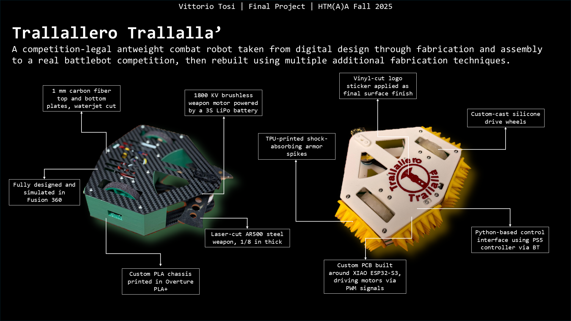
Final Project Video Presentation
Long Version (ca. 2min.)
Short Version (ca. 1min.)
To Conclude
This course completely changed how I think about making. I genuinely loved every part of it, and it sparked a deep interest in digital fabrication that I fully plan to keep pursuing. Huge thanks to Neil, Gert, Anthony, Ryan, Tom, Carlos, Elijah, Aditi, Carlotta, and Shah for the constant support, guidance, and patience throughout the semester. Building on this experience, I’m now planning to design and build a 12-lb combat robot to officially compete in the spring, with the goal of earning a spot at the World Finals. If anyone reading this is interested in getting involved, reach out - I’d love to build this next one as a team.