
Introduction
This week’s work addresses two parallel objectives from the class: the Networking and Communications assignment, which requires designing and connecting a wired or wireless node with a network or bus address and a local input or output device; and the Application Interface assignment, which requires writing an application that interfaces a user with an input and/or output device that I made. As anticipated last week, I combined both into a single integrated system that advances my ongoing combat robot project.
My action plan is to build a wireless receiver module for my robot, based on an ESP32-S3, capable of driving both a drive ESC and Weapon ESC. Instead of relying on a commercial radio transmitter/receiver pair, the goal is to implement a custom communication stack that would allow me to control the robot directly from my laptop over Wi-Fi, using an application that I wrote.
At a high level, the system consists of two parts. On the robot, the ESP32-S3 runs in Wi-Fi Access Point mode, creating the “Trallallero-TrallaLAN” network and hosting a server at 192.168.4.1 that receives motor commands. The firmware parses each packet and converts the left/right values into 50 Hz RC-style pulses for the drive ESC. On the laptop, a Python application reads the arrow keys, computes differential-drive outputs with acceleration ramping, and sends them over.
Hardware
Components Used
The foundation of this week’s work is a custom PCB built around an ESP32-S3, designed to serve as the robot’s wireless receiver and motor-control node. The key hardware components in the system are:
- Custom ESP32-S3 PCB – the main control board I designed for this assignment, hosting the microcontroller and serving as the wireless communication node.
- Repeat Robotics Dual Brushed ESC (DESC) – receives PWM commands from the ESP32-S3 and drives the left and right brushed DC motors.
- Two brushed DC drive motors – the drivetrain actuators controlled by the DESC.
- ReadyToSky 35A BLHeli_S ANT weapon ESC – a dedicated ESC that receives a separate PWM signal from the ESP32-S3 and drives the weapon motor.
- Brushless weapon motor – the motor that spins the weapon, controlled via the ReadyToSky weapon ESC.
- LiPo battery (future power source) – while current testing is done over USB power for simplicity and safety, the plan is for the receiver board and ESC to be powered directly by the robot’s LiPo battery (some wiring work still needed to make this work).
PCB Assembly & Electronics Integration
For this assignment, I needed to design a custom PCB to host the ESP32-S3. A huge shoutout goes to Anthony, who guided me through the design choices and the overall workflow of building a reliable control board.
A key question at the start was how to power the board inside the robot. The bot runs on a 3S LiPo battery (~12.6 V), while the ESP32-S3 requires 5V. I considered two options:
- Powering the board directly from the robot’s LiPo battery: This would require adding a dedicated voltage regulator to step the 3S battery voltage down to a safe level for the XIAO.
- Using a 5 V output from the drive ESC: Many ESCs provide a regulated 5 V supply, but relying on this can introduce noise or power instability when the motors draw high current.
For robustness, I decided to include a 5 V linear regulator on the PCB, so the board can be safely powered from the LiPo battery independently of the ESC’s internal electronics.
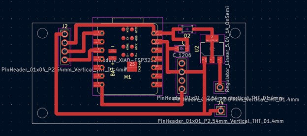
The PCB integrates the following components, each chosen for a specific purpose:
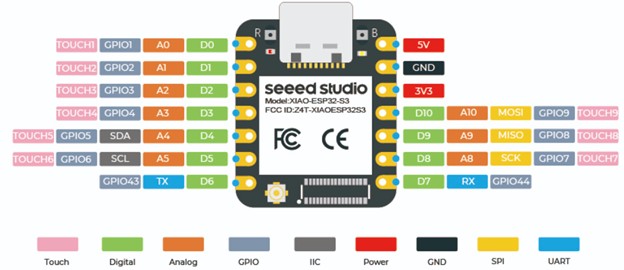
- Seeed Studio XIAO ESP32-S3 Module: It connects over Wi-Fi, receives commands from the laptop, and generates the PWM signals for the ESC.
- 5 V Linear Voltage Regulator: Takes the 12 V from the robot’s battery and brings it down to 5 V so the ESP32 doesn’t burn out (datasheet here: https://www.onsemi.com/pdf/datasheet/ncp1117-d.pdf)
- Schottky Diode: Placed before the regulator to protect the board from accidental reverse-polarity and voltage spikes. (Datasheet here: https://www.st.com/content/ccc/resource/technical/document/datasheet/c6/32/d4/4a/28/d3/4b/11/CD00004930.pdf/files/CD00004930.pdf/jcr:content/translations/en.CD00004930.pdf)
- Capacitor: This 10 µF capacitor smooths and stabilizes the voltage going into the regulator. It helps prevent dips or noise from the LiPo battery from reaching the ESP32.
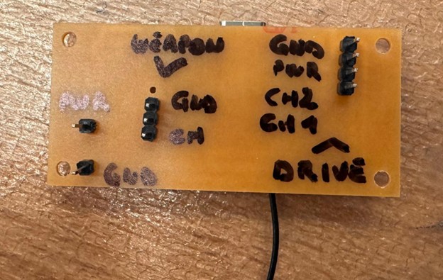
- Pin Headers for the Drive ESC: There are two 4-pin headers. These connect to:
- Channel 1 signal
- Channel 2 signal
- Ground
- 5 V
- Pin Headers for the Weapon ESC: There are three 3-pin headers reserved for the weapon ESC.
- Battery Input Header: A simple 1-pin header where the LiPo battery voltage enters the board.
- Ground Header: A dedicated ground pin that ties the PCB ground to the robot’s ground.
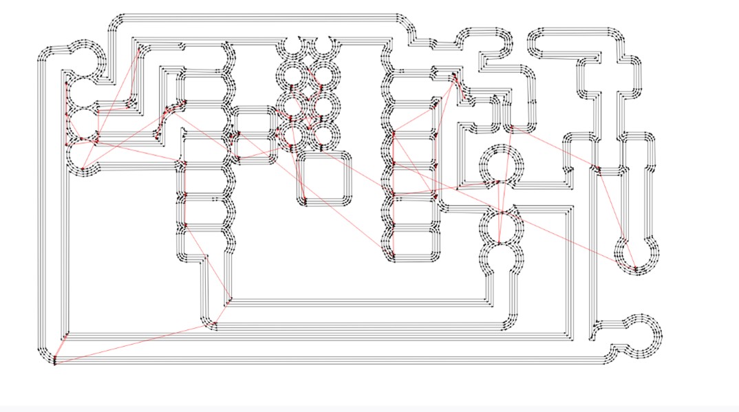
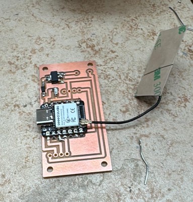
I designed it in KiCad and used mill traces of 1mm. Then went over to Quentin's website to generate the pictures needed for milling.


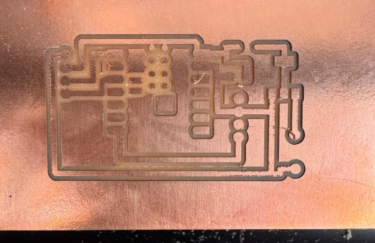
Below are the photos showing the full processes of milling the PCB (took two tries) and soldering the XIAO and all components.
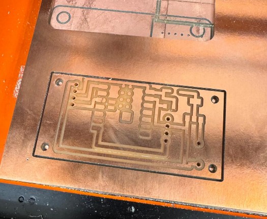
Here below the final board.
Pin Mapping
To control the drive ESC, I used two GPIO pins from the XIAO ESP32-S3 that can output stable PWM signals. The mapping is simple:
- Channel 1 (left motor) → D2 / GPIO3
- Channel 2 (right motor) → D0 / GPIO1
Other pin headers on the PCB (the three 3-pin headers for the weapon ESC) were prepared for future work but not used in this assignment.
Software
Connecting the Board to the Arduino IDE
To program the ESP32-S3, I first had to configure the Arduino IDE so it could recognize the board. The steps were straightforward:
- Install the ESP32 board package
- Open File → Preferences
- In “Additional Boards Manager URLs”, add:
https://espressif.github.io/arduino-esp32/package_esp32_index.json - Then go to Tools → Board → Boards Manager
- Search for “esp32 by Espressif Systems” and install it
- Select the correct ESP32-S3 board
- Go to Tools → Board → esp32
- Select: ESP32S3 Dev Module
- Adjust the required board settings
Under Tools, set:
- USB CDC On Boot → Enabled
- Upload Mode → UART0 / USB
After these settings were applied, the Arduino IDE was able to detect the board on COM6, compile the firmware, and upload it without issues.
First Test Code: Spinning the wheels
Before dealing with Wi-Fi, I first wanted to check that the ESP32-S3 + ESC + motors actually worked together. The goal of this first firmware was simple: type two numbers in the Arduino Serial Monitor (between −100 and 100) and see the wheels spin.
The Repeat Robotics ESC expects a standard RC servo signal:
- Frequency: 50 Hz → one pulse every 20 ms
- Pulse width:
- ~1000 µs = full reverse
- ~1500 µs = neutral
- ~2000 µs = full forward
So the code does three main things:
- Define the PWM and RC ranges
- PWM_FREQ = 50 sets the ESC update rate.
- The RC pulse limits define how we map our −100…100 values into actual microseconds.
- Convert “−100…100” into a duty cycle the LEDC hardware understands
- valueToPulse() takes a user value between −100 and 100 and maps it to 1000–2000 µs.
- pulseToDuty() converts that pulse width into a 0…16383 duty value for the ESP32’s LEDC hardware.
- writePulseUS() is a helper that writes the correct duty to the chosen pin.
- Apply those pulses to the two ESC channels
- The right channel is negated (-ch2_val) to fix the fact that one wheel was spinning in the opposite direction.
Finally, the loop() reads lines from the Serial Monitor
Full code
// ESP32-S3 controlling Repeat Robotics Dual Brushed ESC (DESC)
// Core v3.x compatible (uses ledcAttach / ledcWrite)
//
// CH1: GPIO3 (D2)
// CH2: GPIO1 (D0)
//
// Control from Serial: type two numbers -100..100, e.g. "50 -50" then Enter

#include

// Pin definitions
const int CH1_PIN = 3;   // D2 / GPIO3
const int CH2_PIN = 1;   // D0 / GPIO1

// PWM settings
const int PWM_FREQ     = 50;   // 50 Hz -> 20 ms period (RC standard)
const int PWM_RES_BITS = 14;   // 14-bit resolution (0..16383)

// RC pulse limits (microseconds)
const int RC_MIN_US     = 1000; // full reverse (safe default)
const int RC_MAX_US     = 2000; // full forward (safe default)
const int RC_NEUTRAL_US = 1500; // neutral/stop

// Map a value in [-100, 100] to RC pulse in microseconds
int valueToPulse(int val) {
  if (val < -100) val = -100;
  if (val > 100)  val = 100;
  long pulse = map(val, -100, 100, RC_MIN_US, RC_MAX_US);
  return (int)pulse;
}

// Convert pulse width (µs) to LEDC duty for given freq/resolution
uint32_t pulseToDuty(int pulseWidthUs) {
  uint32_t maxDuty = (1UL << PWM_RES_BITS) - 1; // e.g. 16383 for 14 bits
  // duty = pulse_us * freq / 1e6 * maxDuty
  uint64_t duty = (uint64_t)pulseWidthUs * PWM_FREQ * maxDuty / 1000000ULL;
  return (uint32_t)duty;
}

// Write RC pulse to a specific pin using LEDC
void writePulseUS(int pin, int pulseWidthUs) {
  uint32_t duty = pulseToDuty(pulseWidthUs);
  ledcWrite(pin, duty);
}

void setChannelValues(int ch1_val, int ch2_val) {
  int ch1_pulse = valueToPulse(ch1_val);
  int ch2_pulse = valueToPulse(-ch2_val); // <-- note the minus

  writePulseUS(CH1_PIN, ch1_pulse);
  writePulseUS(CH2_PIN, ch2_pulse);

  Serial.print("CH1: ");
  Serial.print(ch1_val);
  Serial.print(" (");
  Serial.print(ch1_pulse);
  Serial.print(" us)  |  CH2: ");
  Serial.print(ch2_val);
  Serial.print(" (");
  Serial.print(ch2_pulse);
  Serial.println(" us)");
}

String inputLine = "";

void setup() {
  Serial.begin(115200);
  delay(1000);
  Serial.println("\nESP32-S3 + Repeat Dual ESC control (core v3.x)");
  Serial.println("Type two numbers between -100 and 100, e.g.:  0 0   or   50 -50");

  // Setup LEDC PWM on both pins (new API)
  // ledcAttach(pin, freq, resolutionBits)
  if (!ledcAttach(CH1_PIN, PWM_FREQ, PWM_RES_BITS)) {
    Serial.println("Error: ledcAttach failed on CH1_PIN");
  }
  if (!ledcAttach(CH2_PIN, PWM_FREQ, PWM_RES_BITS)) {
    Serial.println("Error: ledcAttach failed on CH2_PIN");
  }

  // Start at neutral on both channels
  setChannelValues(0, 0);
}

void loop() {
  // Read a full line from Serial (until '\n')
  while (Serial.available()) {
    char c = Serial.read();
    if (c == '\r') continue; // ignore CR (Windows)
    if (c == '\n') {
      if (inputLine.length() > 0) {
        int ch1 = 0, ch2 = 0;
        int parsed = sscanf(inputLine.c_str(), "%d %d", &ch1, &ch2);
        if (parsed == 2) {
          setChannelValues(ch1, ch2);
        } else if (parsed == 1) {
          setChannelValues(ch1, ch1);
        } else {
          Serial.println("Parse error. Use:     e.g.  30 -30");
        }
      }
      inputLine = "";
    } else {
      inputLine += c;
    }
  }

  // PWM keeps running in hardware; nothing else needed here
}
Adding Keyboard Control with a Python Script
Once I could spin the wheels by typing values in the Arduino Serial Monitor, the next step was to make the robot react to the arrow keys in real time. The idea was to write a Python script that:
- opens the same serial port used by Arduino (e.g. COM6)
- listens for arrow key presses (↑ ↓ ← →)
- converts those presses into left/right speed values between −100 and 100
- sends lines like “30 -30\n” to the ESP32, in the same format as before
- supports space for an emergency stop and q to quit
Because the Arduino code already expected text commands in the form L R over Serial, I didn’t need to change the Arduino code at all. The Python script simply replaces my hands typing values into the Serial Monitor.
The Python script has a few key parts:
- Configuration and state
- PORT and BAUD match the ESP32 serial connection.
- MAX_SPEED controls how fast the bot drives forward/backward
- TURN_STRENGTH controls how strong the turning is.
- state keeps track of which arrow keys are currently held down.
- Computing left/right motor values from keys
- If up is pressed, throttle is positive; if down is pressed, throttle is negative.
- Left and right change the turn value.
- The mixing left = throttle + turn, right = throttle - turn turns the robot by speeding one side up and slowing the other down.
- Finally, both values are clamped so the Arduino still sees numbers in the −100…100 range.
- Handling key presses and releases
- When an arrow key is pressed, the corresponding flag in state becomes True
- When the key is released, it goes back to False.
- Space clears all directions (emergency stop).
- q stops the listener and exits the program.
- Main loop: send commands over Serial
- Opens the serial port to the ESP32.
- Starts a background listener for the keyboard.
- Every 50 ms (time.sleep(0.05)), it:
- computes the current left and right values,
- if they changed, sends a line "L R\n" over Serial.
- On exit, it sends "0 0" once to stop the robot and closes the port.
Full code
import time
import serial
from pynput import keyboard

# === CONFIG ===
PORT = "COM6"        # Change if necessary
BAUD = 115200

MAX_SPEED = 60       # forward/backward strength
TURN_STRENGTH = 60   # turning strength

# ==============

state = {
    "up": False,
    "down": False,
    "left": False,
    "right": False,
}

def compute_motors():
    throttle = 0
    turn = 0

    # forward/back
    if state["up"] and not state["down"]:
        throttle = MAX_SPEED
    elif state["down"] and not state["up"]:
        throttle = -MAX_SPEED

    # left/right
    if state["left"] and not state["right"]:
        turn = -TURN_STRENGTH
    elif state["right"] and not state["left"]:
        turn = TURN_STRENGTH

    # differential mixing
    left = throttle + turn
    right = throttle - turn

    # clamp
    left = max(-100, min(100, left))
    right = max(-100, min(100, right))

    return left, right

def on_press(key):
    try:
        if key == keyboard.Key.up:
            state["up"] = True
        elif key == keyboard.Key.down:
            state["down"] = True
        elif key == keyboard.Key.left:
            state["left"] = True
        elif key == keyboard.Key.right:
            state["right"] = True
        elif key == keyboard.Key.space:
            for k in state:
                state[k] = False
        elif hasattr(key, "char") and key.char == "q":
            print("Quitting...")
            return False
    except Exception:
        pass

def on_release(key):
    if key == keyboard.Key.up:
        state["up"] = False
    elif key == keyboard.Key.down:
        state["down"] = False
    elif key == keyboard.Key.left:
        state["left"] = False
    elif key == keyboard.Key.right:
        state["right"] = False

def main():
    print(f"Opening serial port {PORT} at {BAUD}...")
    ser = serial.Serial(PORT, BAUD, timeout=0.1)
    print("Connected. Use arrow keys to drive, SPACE to stop, 'q' to quit.")
    print("Make sure this window stays focused.")

    listener = keyboard.Listener(on_press=on_press, on_release=on_release)
    listener.start()

    last_left, last_right = None, None

    try:
        while listener.is_alive():
            left, right = compute_motors()
            if left != last_left or right != last_right:
                msg = f"{left} {right}\n"
                ser.write(msg.encode("ascii"))
                print("Sent:", msg.strip())
                last_left, last_right = left, right

            time.sleep(0.05)
    except KeyboardInterrupt:
        pass
    finally:
        try:
            ser.write(b"0 0\n")
        except Exception:
            pass
        ser.close()
        listener.stop()
        print("Stopped and serial closed.")

if __name__ == "__main__":
    main()
Making the System Wireless
To move from a wired Serial connection to a fully wireless robot, I only needed to change the communication layer while keeping the motor-control logic exactly the same. The steps I followed were:
- Create a Wi-Fi network on the ESP32
- I set the ESP32-S3 to Access Point (AP) mode, so it creates its own network called “Trallallero-TrallaLAN”.
- In this mode, the board always uses the default IP address 168.4.1, which makes it easy for my laptop to connect directly to the robot.
- Start a TCP server on the ESP32
- Instead of reading commands from USB Serial, the ESP32 now listens for incoming control messages on a fixed port.
- Once the laptop connects, the board receives text commands ("L R\n") exactly as before.
- Update the Python controller to use Wi-Fi instead of Serial
- The script no longer opens COM6; instead it opens a TCP socket.
- It connects to 192.168.4.1 and sends the same motor-command lines.
- The arrow-key logic and mixing computation did not change.
- Keep all the ESC and PWM code identical
- No changes were needed to the motor-control logic.
- The ESC wiring, PWM generation, and mapping from −100…100 values all stayed the same.
- Only the transport layer changed: Serial → Wi-Fi.

Full Arduino Code
// ESP32-S3 + Repeat Robotics Dual Brushed ESC (DESC)
// Wi-Fi AP + TCP control from laptop
// Core v3.x compatible (uses ledcAttach / ledcWrite)
//
// CH1: GPIO3 (D2)  -> left motor
// CH2: GPIO1 (D0)  -> right motor (inverted)
//
// Laptop connects to Wi-Fi "Trallallero-TrallaLAN" and sends "L R\n" over TCP (port 4210)

#include
#include

// --------- Wi-Fi CONFIG ---------
const char* WIFI_SSID     = "Trallallero-TrallaLAN";
const char* WIFI_PASSWORD = "tralla123";   // min 8 chars

const uint16_t TCP_PORT = 4210;
WiFiServer server(TCP_PORT);
WiFiClient client;

// --------- ESC / PWM CONFIG ---------
// Pin definitions
const int CH1_PIN = 3;   // D2 / GPIO3 (left)
const int CH2_PIN = 1;   // D0 / GPIO1 (right)

// PWM settings
const int PWM_FREQ     = 50;   // 50 Hz -> 20 ms period (RC standard)
const int PWM_RES_BITS = 14;   // 14-bit resolution (0..16383)

// RC pulse limits (microseconds)
const int RC_MIN_US     = 1000; // full reverse (safe default)
const int RC_MAX_US     = 2000; // full forward (safe default)
const int RC_NEUTRAL_US = 1500; // neutral/stop

// Map a value in [-100, 100] to RC pulse in microseconds
int valueToPulse(int val) {
  if (val < -100) val = -100;
  if (val > 100)  val = 100;
  long pulse = map(val, -100, 100, RC_MIN_US, RC_MAX_US);
  return (int)pulse;
}

// Convert pulse width (µs) to LEDC duty for given freq/resolution
uint32_t pulseToDuty(int pulseWidthUs) {
  uint32_t maxDuty = (1UL << PWM_RES_BITS) - 1; // e.g. 16383 for 14 bits
  // duty = pulse_us * freq / 1e6 * maxDuty
  uint64_t duty = (uint64_t)pulseWidthUs * PWM_FREQ * maxDuty / 1000000ULL;
  return (uint32_t)duty;
}

// Write RC pulse to a specific pin using LEDC
void writePulseUS(int pin, int pulseWidthUs) {
  uint32_t duty = pulseToDuty(pulseWidthUs);
  ledcWrite(pin, duty);
}

void setChannelValues(int ch1_val, int ch2_val) {
  // CH2 inverted so your left/right directions match real life
  int ch1_pulse = valueToPulse(ch1_val);
  int ch2_pulse = valueToPulse(-ch2_val);  // note the minus

  writePulseUS(CH1_PIN, ch1_pulse);
  writePulseUS(CH2_PIN, ch2_pulse);

  Serial.print("CH1: ");
  Serial.print(ch1_val);
  Serial.print(" (");
  Serial.print(ch1_pulse);
  Serial.print(" us)  |  CH2: ");
  Serial.print(ch2_val);
  Serial.print(" (");
  Serial.print(ch2_pulse);
  Serial.println(" us)");
}

String netLine = "";
unsigned long lastCommandMs = 0;
const unsigned long FAILSAFE_TIMEOUT_MS = 500; // stop if no command for 0.5s

void setup() {
  Serial.begin(115200);
  delay(1000);
  Serial.println("\nESP32-S3 + Repeat Dual ESC + Wi-Fi TCP control");

  // Setup LEDC PWM on both pins
  if (!ledcAttach(CH1_PIN, PWM_FREQ, PWM_RES_BITS)) {
    Serial.println("Error: ledcAttach failed on CH1_PIN");
  }
  if (!ledcAttach(CH2_PIN, PWM_FREQ, PWM_RES_BITS)) {
    Serial.println("Error: ledcAttach failed on CH2_PIN");
  }

  // Start at neutral on both channels
  setChannelValues(0, 0);

  // Wi-Fi AP setup
  WiFi.mode(WIFI_AP);
  bool ap_ok = WiFi.softAP(WIFI_SSID, WIFI_PASSWORD);
  if (ap_ok) {
    Serial.print("Wi-Fi AP started. SSID: ");
    Serial.print(WIFI_SSID);
    Serial.print("  password: ");
    Serial.println(WIFI_PASSWORD);
    Serial.print("AP IP address: ");
    Serial.println(WiFi.softAPIP()); // usually 192.168.4.1
  } else {
    Serial.println("ERROR: Failed to start Wi-Fi AP");
  }

  server.begin();
  Serial.print("TCP server listening on port ");
  Serial.println(TCP_PORT);
}

void handleClientData() {
  // Accept new client if none or disconnected
  if (!client || !client.connected()) {
    WiFiClient newClient = server.available();
    if (newClient) {
      client = newClient;
      Serial.println("New TCP client connected.");
      netLine = "";
    }
  }

  if (client && client.connected() && client.available()) {
    while (client.available()) {
      char c = client.read();
      if (c == '\r') continue; // ignore CR
      if (c == '\n') {
        if (netLine.length() > 0) {
          int ch1 = 0, ch2 = 0;
          int parsed = sscanf(netLine.c_str(), "%d %d", &ch1, &ch2);
          if (parsed == 2) {
            setChannelValues(ch1, ch2);
            lastCommandMs = millis();
          } else if (parsed == 1) {
            setChannelValues(ch1, ch1);
            lastCommandMs = millis();
          } else {
            Serial.print("Parse error on line: ");
            Serial.println(netLine);
          }
        }
        netLine = "";
      } else {
        netLine += c;
      }
    }
  }
}

void loop() {
  handleClientData();

  // Failsafe: if no command in some time, stop motors
  unsigned long now = millis();
  if (now - lastCommandMs > FAILSAFE_TIMEOUT_MS) {
    setChannelValues(0, 0);
  }

  // (Optional) you can still type commands via USB Serial for debugging:
  // e.g., send "30 30" from Serial Monitor if you want.
  if (Serial.available()) {
    String line = Serial.readStringUntil('\n');
    line.trim();
    if (line.length() > 0) {
      int ch1 = 0, ch2 = 0;
      int parsed = sscanf(line.c_str(), "%d %d", &ch1, &ch2);
      if (parsed == 2) {
        setChannelValues(ch1, ch2);
        lastCommandMs = now;
      } else if (parsed == 1) {
        setChannelValues(ch1, ch1);
        lastCommandMs = now;
      } else {
        Serial.print("Serial parse error on line: ");
        Serial.println(line);
      }
    }
  }
}
Full Python Code
import time
import socket
from pynput import keyboard

# === CONFIG ===
HOST = "192.168.4.1"   # ESP32 AP default IP
PORT = 4210            # must match TCP_PORT in Arduino code

MAX_SPEED = 60         # forward/backward strength (-100..100)
TURN_STRENGTH = 60     # turning strength (-100..100)

RAMP_RATE = 5          # max change per tick (every UPDATE_DT) -> ~100 units/sec
UPDATE_DT = 0.05       # loop period in seconds
# ==============

state = {
    "up": False,
    "down": False,
    "left": False,
    "right": False,
}

def compute_motors():
    """Compute target left/right values (-100..100) from key state."""
    throttle = 0
    turn = 0

    # Forward / backward
    if state["up"] and not state["down"]:
        throttle = MAX_SPEED
    elif state["down"] and not state["up"]:
        throttle = -MAX_SPEED

    # Left / right
    if state["left"] and not state["right"]:
        turn = -TURN_STRENGTH   # left
    elif state["right"] and not state["left"]:
        turn = TURN_STRENGTH    # right

    # Differential drive mixing
    # (flipped so RIGHT arrow = turn right with your current wiring)
    left = throttle - turn
    right = throttle + turn

    # Clamp to [-100, 100]
    left = max(-100, min(100, left))
    right = max(-100, min(100, right))

    return left, right

def ramp(value, target):
    """Slew-rate limiter: move value toward target by at most RAMP_RATE."""
    if value < target:
        return min(value + RAMP_RATE, target)
    elif value > target:
        return max(value - RAMP_RATE, target)
    return value

def on_press(key):
    try:
        if key == keyboard.Key.up:
            state["up"] = True
        elif key == keyboard.Key.down:
            state["down"] = True
        elif key == keyboard.Key.left:
            state["left"] = True
        elif key == keyboard.Key.right:
            state["right"] = True
        elif key == keyboard.Key.space:
            # emergency stop: clear all directions
            for k in state:
                state[k] = False
        elif hasattr(key, "char") and key.char == "q":
            print("Quitting...")
            return False
    except Exception:
        pass

def on_release(key):
    if key == keyboard.Key.up:
        state["up"] = False
    elif key == keyboard.Key.down:
        state["down"] = False
    elif key == keyboard.Key.left:
        state["left"] = False
    elif key == keyboard.Key.right:
        state["right"] = False

def main():
    print(f"Connecting to {HOST}:{PORT} ...")
    sock = socket.socket(socket.AF_INET, socket.SOCK_STREAM)
    sock.settimeout(5.0)
    sock.connect((HOST, PORT))
    sock.settimeout(None)
    print("Connected. Use arrow keys to drive, SPACE to stop, 'q' to quit.")
    print("Make sure this window stays focused.")

    listener = keyboard.Listener(on_press=on_press, on_release=on_release)
    listener.start()

    current_left = 0.0
    current_right = 0.0
    last_left = None
    last_right = None

    try:
        while listener.is_alive():
            target_left, target_right = compute_motors()

            # Apply ramping
            current_left = ramp(current_left, target_left)
            current_right = ramp(current_right, target_right)

            # Only send if changed
            if current_left != last_left or current_right != last_right:
                msg = f"{int(current_left)} {int(current_right)}\n"
                sock.sendall(msg.encode("ascii"))
                print("Sent:", msg.strip())
                last_left, last_right = current_left, current_right

            time.sleep(UPDATE_DT)
    except KeyboardInterrupt:
        pass
    finally:
        try:
            sock.sendall(b"0 0\n")
        except Exception:
            pass
        sock.close()
        listener.stop()
        print("Stopped, socket closed.")

if __name__ == "__main__":
    main()
Adding the weapon control (via cable)
It was then time to test the weapon. To test the weapon system, I extended the existing firmware so that the ESP32-S3 could also drive the ReadyToSky 35A BLHeli_S weapon ESC connected to GPIO43 (D6). The goal was to control the weapon speed with a simple 0–100 value sent over the Serial Monitor. The main elements for the weapon are:
- const int WEAPON_PIN = 43; This defines GPIO43 (D6) as the signal pin for the weapon ESC.
- int weaponValueToPulse(int val) This function takes a weapon command between 0 and 100 and converts it into an RC-style pulse width between 1000 µs (stopped) and 2000 µs (full throttle):
- 0 → 1000 µs → weapon off
- 100 → 2000 µs → maximum speed
- void setWeaponValue(int weapon_val) This function:
- Calls weaponValueToPulse(weapon_val) to get the right pulse width.
- Uses writePulseUS(WEAPON_PIN, pulse) to send this pulse to the weapon ESC using the ESP32’s hardware PWM.
- Prints a debug line like WEAPON | 30 (1500 us) so I can see the commanded value and pulse width in the Serial Monitor.
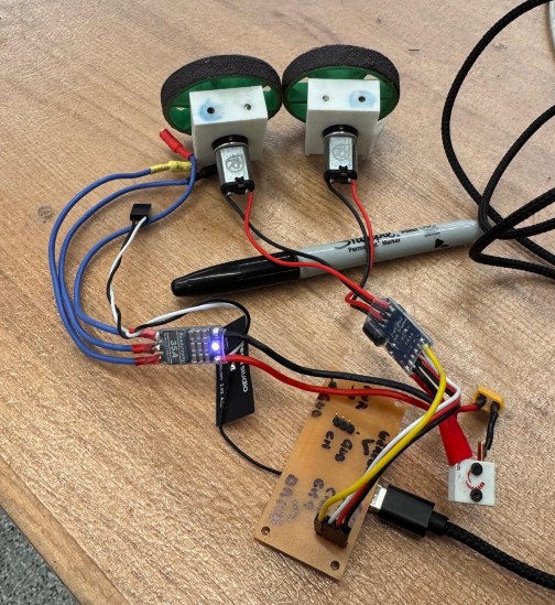
To check that the weapon ESC and motor were working correctly with this code, I used the following procedure:
- Physical setup
- Connected the weapon ESC signal wire to the pin header tied to GPIO43 (D6).
- Made sure the ESC ground and the board ground were connected.
- Plugged the LiPo battery into the ESC to power the weapon motor.
- Kept the weapon removed for safety.
- Connect the ESP32-S3 to the laptop
- Plugged the ESP32-S3 into my laptop via USB.
- Opened the Arduino Serial Monitor.
- Send test commands over Serial
- Started with everything stopped by sending: 0 0 0 (the first two values are for drive and were ignored for this test, the third value is the weapon command).
- Then gradually increased the weapon value, for example:
- 0 0 10
- 0 0 20
- 0 0 30
- … up to 0 0 100
Full Code
// ESP32-S3 controlling Repeat Robotics Dual Brushed ESC (DESC)
// + ReadyToSky 35A BLHeli_S ANT weapon ESC
// Core v3.x compatible (uses ledcAttach / ledcWrite)
//
// Drive CH1: GPIO3 (D2)
// Drive CH2: GPIO1 (D0)
// Weapon:    GPIO43 (D6)
//
// Control from Serial:
//   2 values  -> drive only:          "<ch1> <ch2>"
//   3 values  -> drive + weapon:      "<ch1> <ch2> <weapon>"
//   1 value   -> both drive motors:   "<ch>"

#include <Arduino.h>

// Pin definitions
const int CH1_PIN     = 3;   // D2 / GPIO3 (drive left)
const int CH2_PIN     = 1;   // D0 / GPIO1 (drive right)
const int WEAPON_PIN  = 43;  // D6 / GPIO43 (weapon ESC)

// PWM settings
const int PWM_FREQ     = 50;   // 50 Hz -> 20 ms period (RC standard)
const int PWM_RES_BITS = 14;   // 14-bit resolution (0..16383)

// RC pulse limits (microseconds)
const int RC_MIN_US     = 1000; // min throttle / full reverse
const int RC_MAX_US     = 2000; // max throttle / full forward
const int RC_NEUTRAL_US = 1500; // neutral/stop (not used for weapon)

// Map a value in [-100, 100] to RC pulse in microseconds (drive)
int valueToPulse(int val) {
  if (val < -100) val = -100;
  if (val > 100)  val = 100;
  long pulse = map(val, -100, 100, RC_MIN_US, RC_MAX_US);
  return (int)pulse;
}

// Map a value in [0, 100] to RC pulse in microseconds (weapon)
int weaponValueToPulse(int val) {
  if (val < 0)   val = 0;
  if (val > 100) val = 100;
  long pulse = map(val, 0, 100, RC_MIN_US, RC_MAX_US);
  return (int)pulse;
}

// Convert pulse width (µs) to LEDC duty for given freq/resolution
uint32_t pulseToDuty(int pulseWidthUs) {
  uint32_t maxDuty = (1UL << PWM_RES_BITS) - 1; // e.g. 16383 for 14 bits
  // duty = pulse_us * freq / 1e6 * maxDuty
  uint64_t duty = (uint64_t)pulseWidthUs * PWM_FREQ * maxDuty / 1000000ULL;
  return (uint32_t)duty;
}

// Write RC pulse to a specific pin using LEDC
void writePulseUS(int pin, int pulseWidthUs) {
  uint32_t duty = pulseToDuty(pulseWidthUs);
  ledcWrite(pin, duty);
}

void setDriveValues(int ch1_val, int ch2_val) {
  int ch1_pulse = valueToPulse(ch1_val);
  int ch2_pulse = valueToPulse(-ch2_val); // right side inverted

  writePulseUS(CH1_PIN, ch1_pulse);
  writePulseUS(CH2_PIN, ch2_pulse);

  Serial.print("DRIVE  |  CH1: ");
  Serial.print(ch1_val);
  Serial.print(" (");
  Serial.print(ch1_pulse);
  Serial.print(" us)  |  CH2: ");
  Serial.print(ch2_val);
  Serial.print(" (");
  Serial.print(ch2_pulse);
  Serial.println(" us)");
}

void setWeaponValue(int weapon_val) {
  int pulse = weaponValueToPulse(weapon_val);
  writePulseUS(WEAPON_PIN, pulse);

  Serial.print("WEAPON | ");
  Serial.print(weapon_val);
  Serial.print(" (");
  Serial.print(pulse);
  Serial.println(" us)");
}

String inputLine = "";

void setup() {
  Serial.begin(115200);
  delay(1000);
  Serial.println("\nESP32-S3 + Drive ESC + Weapon ESC control");
  Serial.println("Type:");
  Serial.println("  <ch1> <ch2>                (drive only, -100..100)");
  Serial.println("  <ch1> <ch2> <weapon>       (drive + weapon, weapon 0..100)");
  Serial.println("  <ch>                       (same value on both drive motors)");

  // Setup LEDC PWM on all three pins (new API)
  if (!ledcAttach(CH1_PIN, PWM_FREQ, PWM_RES_BITS)) {
    Serial.println("Error: ledcAttach failed on CH1_PIN");
  }
  if (!ledcAttach(CH2_PIN, PWM_FREQ, PWM_RES_BITS)) {
    Serial.println("Error: ledcAttach failed on CH2_PIN");
  }
  if (!ledcAttach(WEAPON_PIN, PWM_FREQ, PWM_RES_BITS)) {
    Serial.println("Error: ledcAttach failed on WEAPON_PIN");
  }

  // Start at neutral on drive and weapon stopped
  setDriveValues(0, 0);
  setWeaponValue(0);
}

void loop() {
  // Read a full line from Serial (until '\n')
  while (Serial.available()) {
    char c = Serial.read();
    if (c == '\r') continue; // ignore CR (Windows)
    if (c == '\n') {
      if (inputLine.length() > 0) {
        int ch1 = 0, ch2 = 0, weapon = 0;
        int parsed = sscanf(inputLine.c_str(), "%d %d %d", &ch1, &ch2, &weapon);

        if (parsed == 3) {
          setDriveValues(ch1, ch2);
          setWeaponValue(weapon);
        } else if (parsed == 2) {
          setDriveValues(ch1, ch2);
        } else if (parsed == 1) {
          setDriveValues(ch1, ch1);
        } else {
          Serial.println("Parse error. Use:");
          Serial.println("  <ch1> <ch2>            or  <ch1> <ch2> <weapon>");
        }
      }
      inputLine = "";
    } else {
      inputLine += c;
    }
  }
  // PWM keeps running in hardware; nothing else needed here
}
Making the System Wireless (again)
It was now time again to put everything together. As before, this required a finetuning of the python and Arduino codes. Full codes here below.
Full Arduino Code
// ESP32-S3 + Wi-Fi AP + TCP control
// Drive: Repeat Robotics Dual Brushed ESC (DESC)
// Weapon: ReadyToSky 35A BLHeli_S ANT ESC
//
// Drive CH1: GPIO3 (D2)  -> left
// Drive CH2: GPIO1 (D0)  -> right (inverted)
// Weapon:    GPIO43 (D6)
//
// TCP command format (from laptop over Wi-Fi):
//   "<left> <right> <weapon>\n"
//   left/right:  -100..100
//   weapon:       0..100

#include <Arduino.h>
#include <WiFi.h>

// ------- Wi-Fi CONFIG -------
const char* WIFI_SSID     = "TrallaBot";
const char* WIFI_PASSWORD = "tralla123";
const uint16_t TCP_PORT   = 4210;

WiFiServer server(TCP_PORT);
WiFiClient client;

// ------- PINS -------
const int CH1_PIN    = 3;   // D2 / GPIO3 (drive left)
const int CH2_PIN    = 1;   // D0 / GPIO1 (drive right)
const int WEAPON_PIN = 43;  // D6 / GPIO43 (weapon)

// ------- PWM CONFIG -------
const int PWM_FREQ     = 50;   // 50 Hz
const int PWM_RES_BITS = 14;   // 0..16383

// RC pulse limits
const int RC_MIN_US     = 1000;
const int RC_MAX_US     = 2000;
const int RC_NEUTRAL_US = 1500;

// Map drive value [-100,100] to 1000..2000 us
int valueToPulse(int val) {
  if (val < -100) val = -100;
  if (val > 100)  val = 100;
  long pulse = map(val, -100, 100, RC_MIN_US, RC_MAX_US);
  return (int)pulse;
}

// Map weapon value [0,100] to 1000..2000 us
int weaponValueToPulse(int val) {
  if (val < 0)   val = 0;
  if (val > 100) val = 100;
  long pulse = map(val, 0, 100, RC_MIN_US, RC_MAX_US);
  return (int)pulse;
}

uint32_t pulseToDuty(int pulseWidthUs) {
  uint32_t maxDuty = (1UL << PWM_RES_BITS) - 1;
  uint64_t duty = (uint64_t)pulseWidthUs * PWM_FREQ * maxDuty / 1000000ULL;
  return (uint32_t)duty;
}

void writePulseUS(int pin, int pulseWidthUs) {
  uint32_t duty = pulseToDuty(pulseWidthUs);
  ledcWrite(pin, duty);
}

void setDriveValues(int ch1_val, int ch2_val) {
  int ch1_pulse = valueToPulse(ch1_val);
  int ch2_pulse = valueToPulse(-ch2_val);  // invert right

  writePulseUS(CH1_PIN, ch1_pulse);
  writePulseUS(CH2_PIN, ch2_pulse);
}

void setWeaponValue(int weapon_val) {
  int pulse = weaponValueToPulse(weapon_val);
  writePulseUS(WEAPON_PIN, pulse);
}

String netLine = "";

void setup() {
  Serial.begin(115200);
  delay(1000);
  Serial.println("ESP32-S3 Wi-Fi drive + weapon control");

  // PWM setup
  ledcAttach(CH1_PIN,    PWM_FREQ, PWM_RES_BITS);
  ledcAttach(CH2_PIN,    PWM_FREQ, PWM_RES_BITS);
  ledcAttach(WEAPON_PIN, PWM_FREQ, PWM_RES_BITS);

  setDriveValues(0, 0);
  setWeaponValue(0);

  // Wi-Fi AP
  WiFi.mode(WIFI_AP);
  WiFi.softAP(WIFI_SSID, WIFI_PASSWORD);
  IPAddress ip = WiFi.softAPIP();
  Serial.print("AP IP: ");
  Serial.println(ip);

  // TCP server
  server.begin();
  Serial.print("Listening on port ");
  Serial.println(TCP_PORT);
}

void loop() {
  // Accept client if none
  if (!client || !client.connected()) {
    WiFiClient newClient = server.available();
    if (newClient) {
      client.stop();
      client = newClient;
      client.setTimeout(10);
      Serial.println("Client connected");
      setDriveValues(0, 0);
      setWeaponValue(0);
      netLine = "";
    }
    return;
  }

  // Read lines from TCP
  while (client.available()) {
    char c = client.read();
    if (c == '\r') continue;
    if (c == '\n') {
      if (netLine.length() > 0) {
        int l = 0, r = 0, w = 0;
        int parsed = sscanf(netLine.c_str(), "%d %d %d", &l, &r, &w);
        if (parsed >= 2) {
          setDriveValues(l, r);
        }
        if (parsed == 3) {
          setWeaponValue(w);
        }
      }
      netLine = "";
    } else {
      netLine += c;
    }
  }

  // If client disconnects, stop everything
  if (!client.connected()) {
    Serial.println("Client disconnected, stopping all.");
    setDriveValues(0, 0);
    setWeaponValue(0);
  }
}
Full Python Code
import time
import socket
from pynput import keyboard

# === CONFIG ===
HOST = "192.168.4.1"   # ESP32 AP IP
PORT = 4210            # must match TCP_PORT in Arduino code

MAX_SPEED = 60         # forward/backward strength (-100..100)
TURN_STRENGTH = 60     # turning strength (-100..100)

RAMP_RATE_DRIVE   = 5   # drive change per tick  (~100 units/s at 0.05s)
RAMP_RATE_WEAPON  = 2   # weapon change per tick (~40 units/s at 0.05s)
UPDATE_DT = 0.05        # seconds

WEAPON_STEP = 5         # how much W/S change the weapon target (0..100)
# ==============

state = {
    "up": False,
    "down": False,
    "left": False,
    "right": False,
}

weapon_target = 0.0    # desired weapon value (0..100)


def compute_motors():
    """Compute target left/right values (-100..100) from key state."""
    throttle = 0
    turn = 0

    # Forward / backward
    if state["up"] and not state["down"]:
        throttle = MAX_SPEED
    elif state["down"] and not state["up"]:
        throttle = -MAX_SPEED

    # Left / right
    if state["left"] and not state["right"]:
        turn = -TURN_STRENGTH
    elif state["right"] and not state["left"]:
        turn = TURN_STRENGTH

    # Differential drive mixing
    left = throttle - turn
    right = throttle + turn

    # Clamp
    left = max(-100, min(100, left))
    right = max(-100, min(100, right))

    return left, right


def ramp(value, target, rate):
    """Slew-rate limiter: move value toward target by at most `rate`."""
    if value < target:
        return min(value + rate, target)
    elif value > target:
        return max(value - rate, target)
    return value


def on_press(key):
    global weapon_target
    try:
        if key == keyboard.Key.up:
            state["up"] = True
        elif key == keyboard.Key.down:
            state["down"] = True
        elif key == keyboard.Key.left:
            state["left"] = True
        elif key == keyboard.Key.right:
            state["right"] = True
        elif key == keyboard.Key.space:
            # emergency stop for drive (weapon unchanged)
            for k in state:
                state[k] = False
        elif hasattr(key, "char"):
            ch = key.char.lower()
            if ch == "w":
                weapon_target = min(100, weapon_target + WEAPON_STEP)
                print(f"Weapon target: {weapon_target}")
            elif ch == "s":
                weapon_target = max(0, weapon_target - WEAPON_STEP)
                print(f"Weapon target: {weapon_target}")
            elif ch == "q":
                print("Q pressed: full stop and exit.")
                return False  # stops listener -> main loop will exit
    except Exception:
        pass


def on_release(key):
    if key == keyboard.Key.up:
        state["up"] = False
    elif key == keyboard.Key.down:
        state["down"] = False
    elif key == keyboard.Key.left:
        state["left"] = False
    elif key == keyboard.Key.right:
        state["right"] = False


def main():
    global weapon_target
    print(f"Connecting to {HOST}:{PORT} ...")
    sock = socket.socket(socket.AF_INET, socket.SOCK_STREAM)
    sock.settimeout(5.0)
    sock.connect((HOST, PORT))
    sock.settimeout(None)
    print("Connected.")
    print("Arrows = drive, W/S = weapon up/down, Q = stop & quit, SPACE = drive stop.")
    print("Make sure this window stays focused.")

    listener = keyboard.Listener(on_press=on_press, on_release=on_release)
    listener.start()

    current_left = 0.0
    current_right = 0.0
    current_weapon = 0.0

    last_left = None
    last_right = None
    last_weapon = None

    try:
        while listener.is_alive():
            target_left, target_right = compute_motors()

            # Apply ramping to drive
            current_left = ramp(current_left, target_left, RAMP_RATE_DRIVE)
            current_right = ramp(current_right, target_right, RAMP_RATE_DRIVE)

            # Apply smoother ramping to weapon
            current_weapon = ramp(current_weapon, weapon_target, RAMP_RATE_WEAPON)

            if (
                current_left != last_left
                or current_right != last_right
                or current_weapon != last_weapon
            ):
                msg = f"{int(current_left)} {int(current_right)} {int(current_weapon)}\n"
                sock.sendall(msg.encode("ascii"))
                print("Sent:", msg.strip())
                last_left = current_left
                last_right = current_right
                last_weapon = current_weapon

            time.sleep(UPDATE_DT)
    except KeyboardInterrupt:
        pass
    finally:
        # Full stop on exit
        try:
            sock.sendall(b"0 0 0\n")
        except Exception:
            pass
        sock.close()
        listener.stop()
        print("Stopped, socket closed.")


if __name__ == "__main__":
    main()
Next Steps
- Finetune parameters for smoother drive
- Mobile app (TBD)
Final result
Here a video of me testing out the system (shot in W14 after having reprinted some parts).
<
Final Project
Please note that the final project includes a detailed walkthrough of how the combat robot was connected to a PS5 controller. The robot creates its own Wi-Fi network, which the computer connects to. At the same time, the computer pairs with the PS5 controller via Bluetooth. Controller inputs are then read on the computer using Python and transmitted to the robot, where Arduino code converts them into motor commands. The full setup, code, and communication flow are documented step by step on the final project page.
Back to main page.