Introduction
This week is Wildcard Week, where the assignment is to design and fabricate something using a digital process - a workflow involving computer-aided design and computer-aided manufacturing - that wasn’t already covered in another week. The documentation must show which requirements the assignment satisfies and include everything needed for someone else to reproduce the work. Throughout the semester I’ve completed several digital-fabrication processes that fit this category, so I’m documenting them here along with the specific project I carried out this week:
- Cutting 1/8" AR500 steel with a laser cutter
- Cutting 1/8" AR500 steel with a waterjet
- Cutting 1 mm carbon fiber with a waterjet
- Embroidering a logo onto a T-shirt
- Using the ShopBot to paint
Cutting 1/8 thick AR500 steel with a lasercutter
I’ve already documented this process on my Final Project page under “Week 11 – Putting it all together (finally)”. Still, here’s a concise summary: this was the fabrication of the spinning weapon for my combat robot - a steel horizontal bar meant to deliver the bot’s main impact.
I originally cut the piece using the laser cutter, only to later discover that this version wasn’t balanced. All of this took place in the N52 Fabrication Shop on the 3rd floor of the MIT Morningside Academy for Design (MAD). To prep the steel, I first cleaned the surface with a grinder to remove impurities. Then, with help from the shop manager, I walked through the cutting workflow: exporting the weapon profile as a DXF, loading it into the laser cutter software, selecting the correct material and thickness, and exporting the job to a USB. After loading the file into the machine, all that remained was setting the origin with the laser pointer and starting the cut. A few minutes later, the weapon came out clean and sharp -ready for the next stage (which, unfortunately, it never reached, since the piece turned out to be unbalanced).
Cutting 1/8 thick AR500 steel with a water jet
I’ve already documented also this process on my Final Project page under “Week 11 – Putting it all together (finally)”. I returned to N52 but worked on the ground floor in the MakerWorkshop - an incredibly well-equipped, student-run mechanical engineering space packed with everything from 3D printers and laser cutters to a CNC mill, precision lathe, and, most importantly for me, the OMAX 5555 waterjet. With help from the shop manager, I prepped the job: exporting the weapon profile as a DXF, powering on the machine and computer, and waiting the required warm-up period. After loading the file, selecting the correct material and thickness, confirming the toolpath, securing the steel plate, setting the nozzle height and origin, and launching the cut, the OMAX sliced through the metal in just a few minutes. When it finished, I had a perfectly cut, waterjetted weapon ready to mount on the robot.
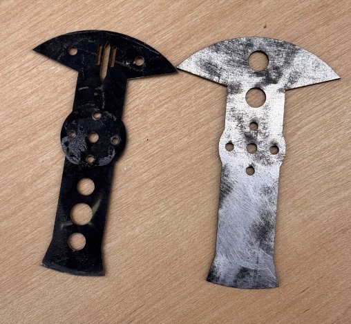
Here a comparison of the two weapons I cut: on the left the water-jetted one, on the right, the laser-cut one.
Cutting 1mm thick carbonfiber with a water jet
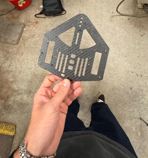
I've gain already documented this process on my Final Project page under “Week 11 – Putting it all together (finally)”. Cutting carbon fiber was key for the success of my robot, however, it has been a very stressful process due to the fact that my carbon fiber order arrived with 4 days of delay and so I had to rush the process.
Considering that carbon fiber is also unsafe to cut out of the water (explain), using the waterjet was my only option and I had to make sure I did it right the first time.
With that said, I used the same machine in N52 builidng as before, and after waiting for the machine to warm up for like 30 min, the cut came out perfect.
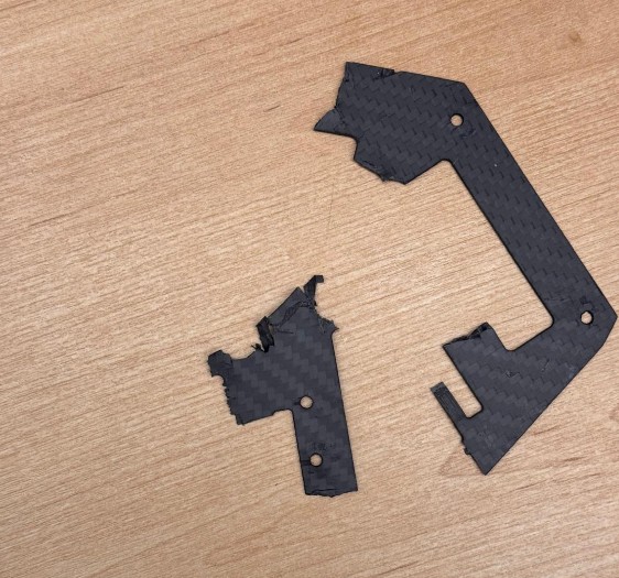
Unfortunately, this is what is left now of one of the two plates:
Embroidering a logo onto a T-shirt
Since I’ll be in New York this weekend, I decided to sign up for the embroidery workshop and try to complete everything by Friday.
Preparing the logo
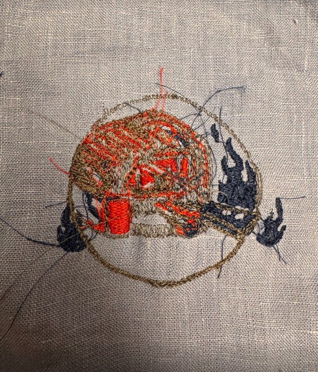
My final project is a combat robot named Trallallero Trallallà, so I wanted to embroider its logo onto a T-shirt. I first created the logo itself - using ChatGPT for the design - and ended up with the version shown below.
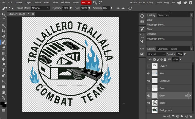
Initially, I thought I needed a separate file for each color in the design, so I opened Photopea (a free online editor) and manually created seven separate color layers.
Preparing the machine
I signed up for the timeslot happening on Thursday evening. The goal is to use the Bother I registered for a Thursday evening timeslot using the Brother SE1800 sewing and embroidery machine. When I arrived, Gert was troubleshooting the machine: it kept failing to stitch correctly, and the issue turned out to be the backing material, which was old and no longer providing enough stability for the fabric during embroidery (apparently it was stretching instead of holding tension).
Since the machine couldn’t be used safely, we decided to regroup on Friday afternoon while Gert continued investigating the issue. In the meantime, I also learned that I didn’t need multiple color files, the embroidery software automatically detects and separates colors on its own.
Doing the job
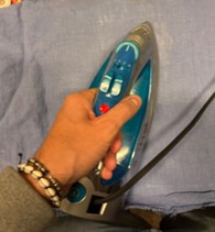
By Friday, the backing issue had been resolved and the machine was functional again, though demand was high since everyone from Thursday had been pushed to the same day. The SE1800 is also not the most reliable machine, so it frequently paused or errored out, slowing progress. Around 6:45 p.m. it was finally my turn, and we decided to start not on a T-shirt but on a piece of scrap fabric that we first ironed flat.
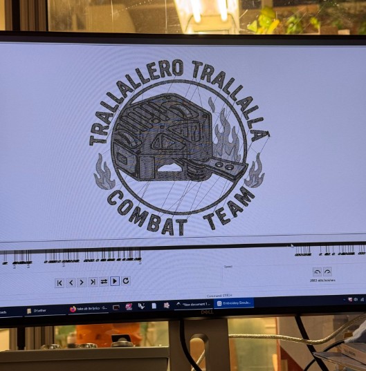
We then loaded my file into the (newly updated) embroidery software, which generates the stitch path, sorts color regions, and previews the sequence the machine will follow. After exporting the file to a USB drive, we launched the job.
The initial stitches looked promising, but as the machine continued, small issues began to accumulate—loose threads, misalignments, and gradual drift. After about 15 minutes, the needle path had shifted roughly half an inch to the left, causing the machine to embroider over areas it had already completed. At that point the output looked messy and unsalvageable, so I decided to stop the test.
It was 7:30 p.m. on Friday, and while this attempt didn’t succeed, I’ll likely try again next week with a simpler, more embroidery-friendly version of the logo.
Using the ShopBot to paint
Since Week 7, I’ve been trying to create a drawing using the ShopBot. This was originally my plan for the “Make Something Big” assignment, inspired by the work of the artist Florian Markus (https://florianmarkus.com/)
His practice centers on CNC-assisted drawing: he programs machines to translate digital linework into physical mark-making, often using pens, pencils, or brushes mounted onto CNC tools. The result is a hybrid between mechanical precision and expressive, hand-like irregularity: exactly the kind of effect I wanted to explore.
By Week 7, I had designed a drawing sized to fit a Large White 24" × 36" stretched canvas.
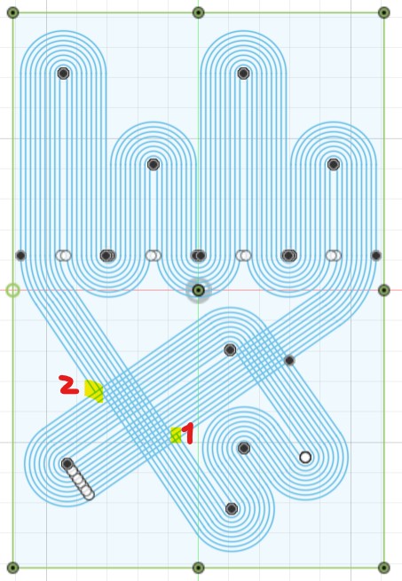
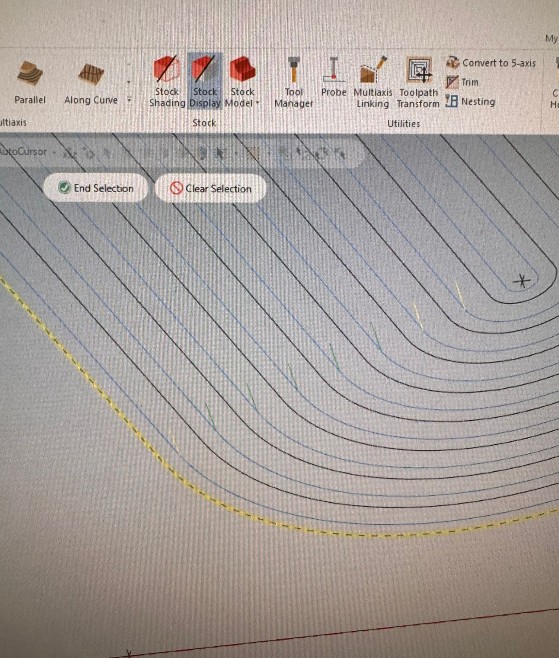
I quickly realized, however, that I’m not good at Mastercam - and programming the toolpath became a nightmare. Thankfully, Christina (the Architecture workshop TA) was extremely generous with her time, and together we built a functioning Mastercam file.
By mid-November, we were finally able to run a first test: we taped a pencil onto the endmill of the ShopBot and plotted the drawing onto cardboard.
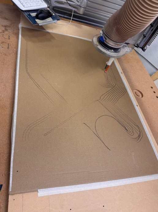
This test revealed a minor but persistent issue in the file: one connection in the drawing wasn’t properly linked, causing the machine to briefly lift when it shouldn’t. I tried troubleshooting for hours and even asked Christina again, but we couldn’t find a clean fix.
Despite this, I decided to move forward and designed 3D-printed tool holders to replace the ShopBot endmill. These parts had three goals:
- Hold a pen or pencil in a perfectly centered position, avoiding the wobble that happens when something is simply taped to the tool.
- Allow quick swapping between pencil and brush.
- Provide an adjustable height mechanism so the tool could lightly touch the canvas.
This height adjustability mattered because the canvas surface isn’t perfectly flat; my solution was to (1) use tools with soft or flexible tips (pen-brush tips, brushes, etc.), and (2) allow micro-adjustments in Z-height.
Unfortunately, since the project fell slightly outside the main HTMAA requirements, the shop had to allocate time to other priority tasks, and we weren’t able to run the machine again before the end of the semester.
definitely still plan to complete this project. I already invested in the paints, tools, and canvases for the intended final version, so I’d really like to see it through, ideally next semester in the Hobby Shop or another CNC-accessible space.