Assignment
- group assignment:
- design a machine that includes mechanism + actuation + automation + function
- build the mechanical parts and operate it manually
- actuate and automate the machine
- document the group project and individual contributions
For the full group documentation, please visit the Neilbot group page.
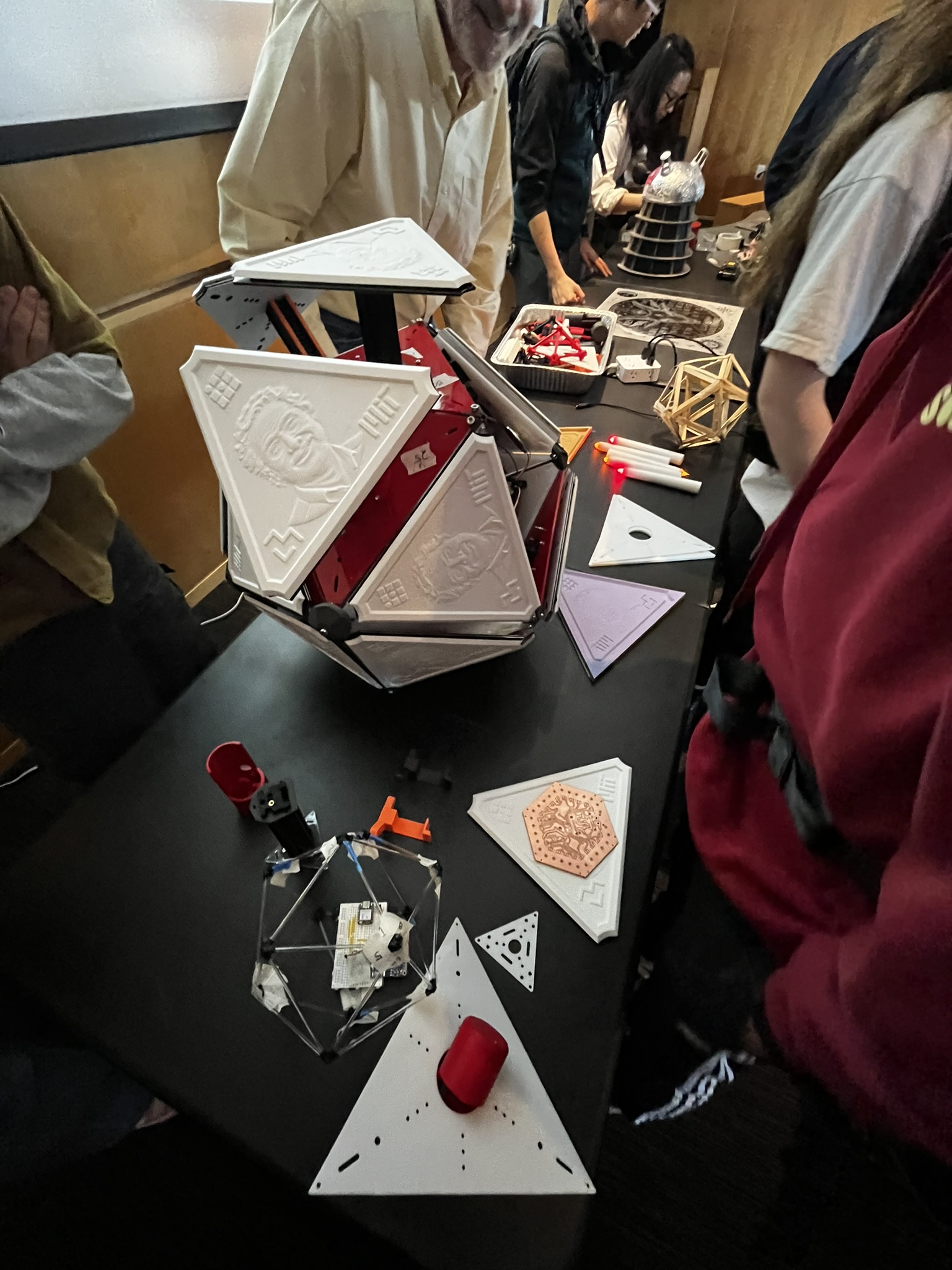
The Machine
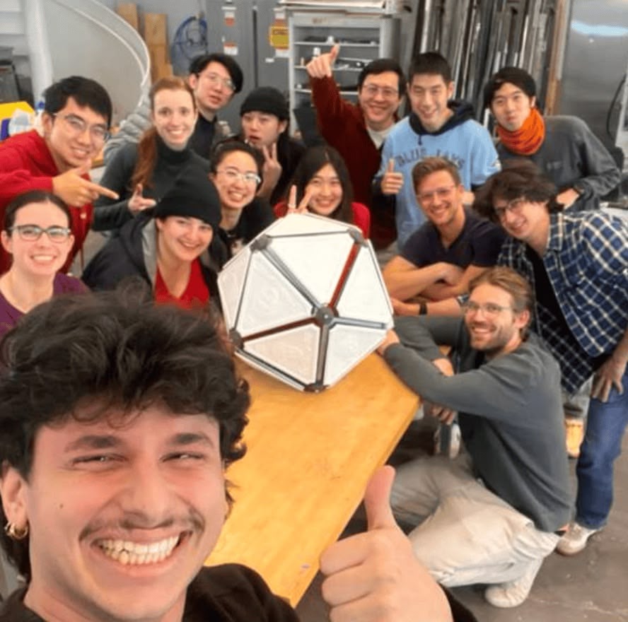
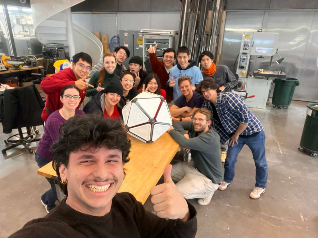
Our section built Neilbot, an icosahedral robot that moves by extending and retracting its 20 triangular faces. The robot uses an IMU sensor to track its orientation in space, and a web-based controller determines which faces to actuate based on the desired movement direction.
I joined the software team alongside Matti, Sun, Miranda, Saetbyeol, and Sophia.
Day 1: IMU Data and Visualization
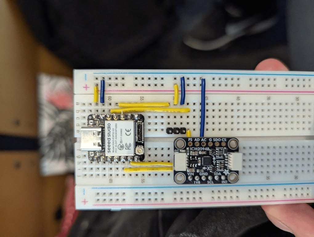
The first task was getting data from the 9-DOF IMU sensor and transmitting it to a laptop for visualization. We used the ICM-20948 breakout board from Adafruit, which provides quaternion orientation data via its onboard Digital Motion Processor (DMP).
WiFi Communication Setup
We set up bi-directional communication between the ESP32 and our laptops using UDP over the MIT Media Lab's MLDEV WiFi network. Sun wrote the networking layer, and we quickly had sensor data streaming to a Node.js server.
TODO: Add setup photo
IMU Data Visualizer
I built a simple web-based visualizer to display the IMU sensor data streaming from the ESP32. This helped the team verify that the sensor was working correctly and that the UDP communication was stable.
TODO: Add visualizer screenshot or video
The challenging part was the 3D math—figuring out how to interpret the quaternion data and translate it into meaningful orientation information for our icosahedron model. Matti and I approached the problem from different angles—he had years of VFX experience working with 3D transforms, while I was trying to reason through it from linear algebra first principles.
We kept talking past each other with different terminology for the same concepts. Eventually, I decided to let Matti and Miranda handle the quaternion math and icosahedron visualization while I moved to building something that would help everyone: a physical testing frame.
Building the Testing Frame
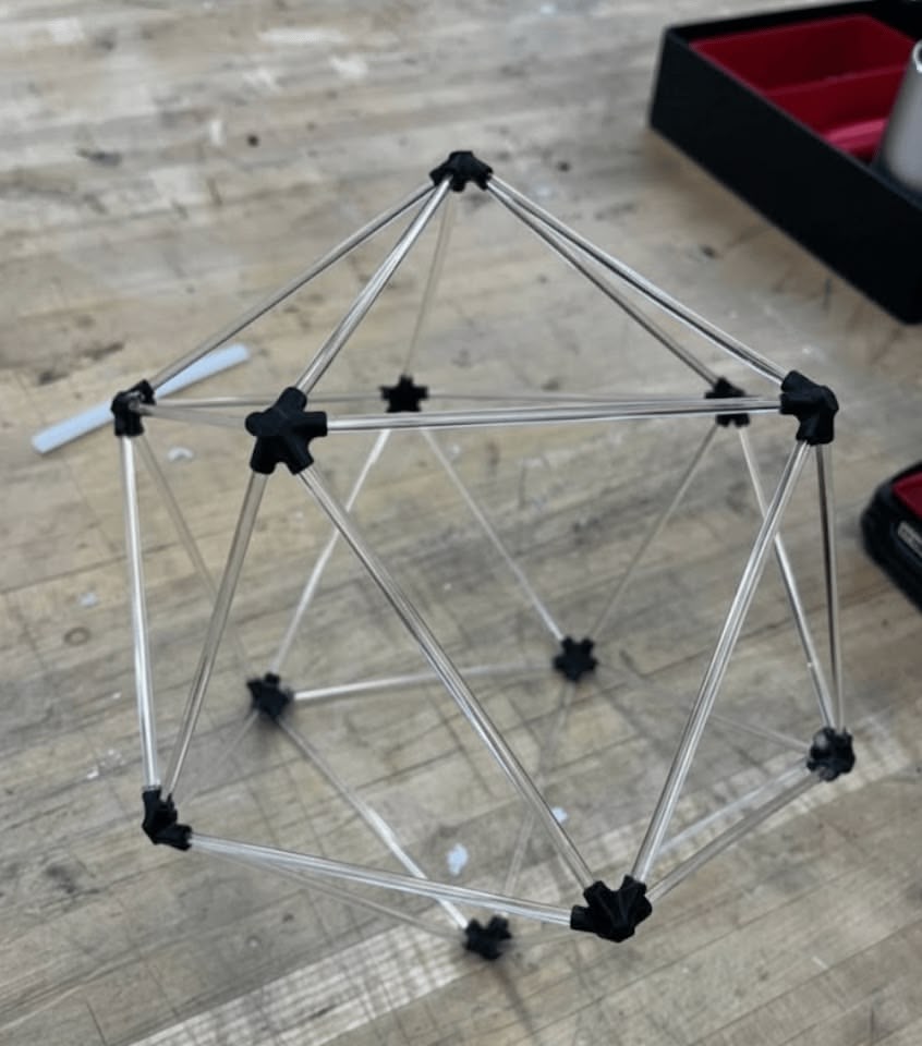
To test the calibration logic without having to imagine an icosahedron floating in the air, I decided to build a physical frame that matched our digital model.
Reusing Week 4 Design
I had already designed icosahedron vertex connectors for Week 4's 3D printing assignment. Each connector accepts five rods at the precise angles needed to form an icosahedron. I printed a fresh batch of these connectors for the testing frame.
For the edges, I ordered clear acrylic dowel rods from Amazon (30pcs 1/8" x 12" Acrylic Dowel Rods). I cut each rod to about 3 inches using pliers. The transparency made it easy to see through the frame while working.
Mounting Plate Design
I designed a simple plate with M3 screw holes to mount the breadboard inside the frame. The plate also had cutouts to accept the 1/8" acrylic rods at the correct angles.
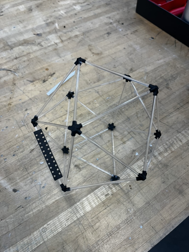
The fit wasn't perfect—I ended up having to hot glue some of the connections—but it was stable enough for testing.
Numbered Faces
Crucially, I numbered each face on the frame to match our software definitions and the D20 dice that Eitan had printed for everyone. I wrapped masking tape around the rods and wrote the corresponding face numbers on them. This seemingly small detail massively sped up our development: when someone said "actuate face 7," everyone knew exactly which physical face that corresponded to.
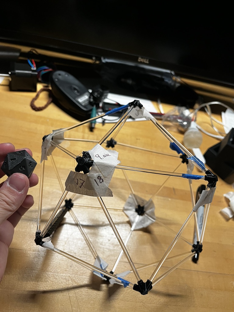
We mounted the breadboard with the MCU, IMU sensor, and later even servos inside this frame. The software team could now rotate the frame and immediately see if the 3D visualization matched reality.
Command Sequencer
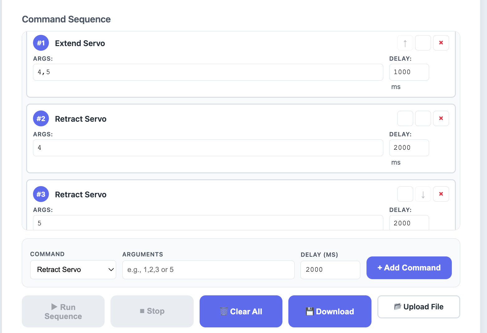
After Matti and Miranda completed the quaternion math and we switched from WiFi/UDP to Bluetooth Low Energy (BLE), I implemented a command sequencer for the web controller.
Why a Sequencer?
We anticipated needing to film the robot moving in specific patterns. Manually clicking buttons in real-time wasn't reliable enough—we needed a way to pre-program sequences of servo commands with precise timing.
Implementation
The sequencer allows you to:
- Add commands (extend servo, retract servo, move servo)
- Set delays between commands in milliseconds
- Import/export sequences as text files
- Execute sequences with visual feedback
// Example sequence format
move_servo 1,2,3 2000   // Extend faces 1-3, wait 2 seconds
move_servo 4,5,6 2000   // Extend faces 4-6, wait 2 seconds
reset 0                 // Reset device
This tool proved essential during filming—we could rehearse and refine movement sequences before committing to a take.
Assembly
As we approached the final build, I moved off software work and joined everyone in the Mars Lab for assembly. The mechanical team had designed a rack-and-pinion mechanism for each face, and there were hundreds of parts to put together.
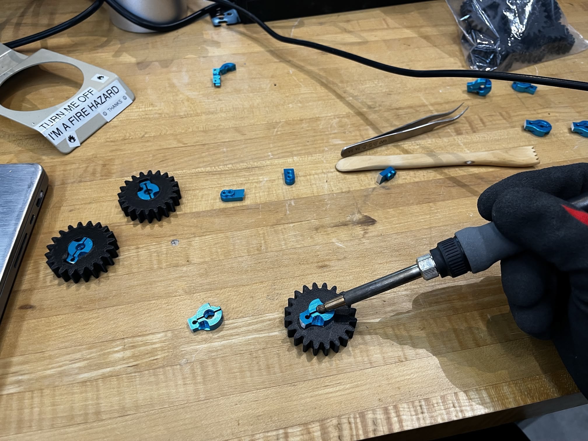
Sanding and Heat-Setting Servo Arms
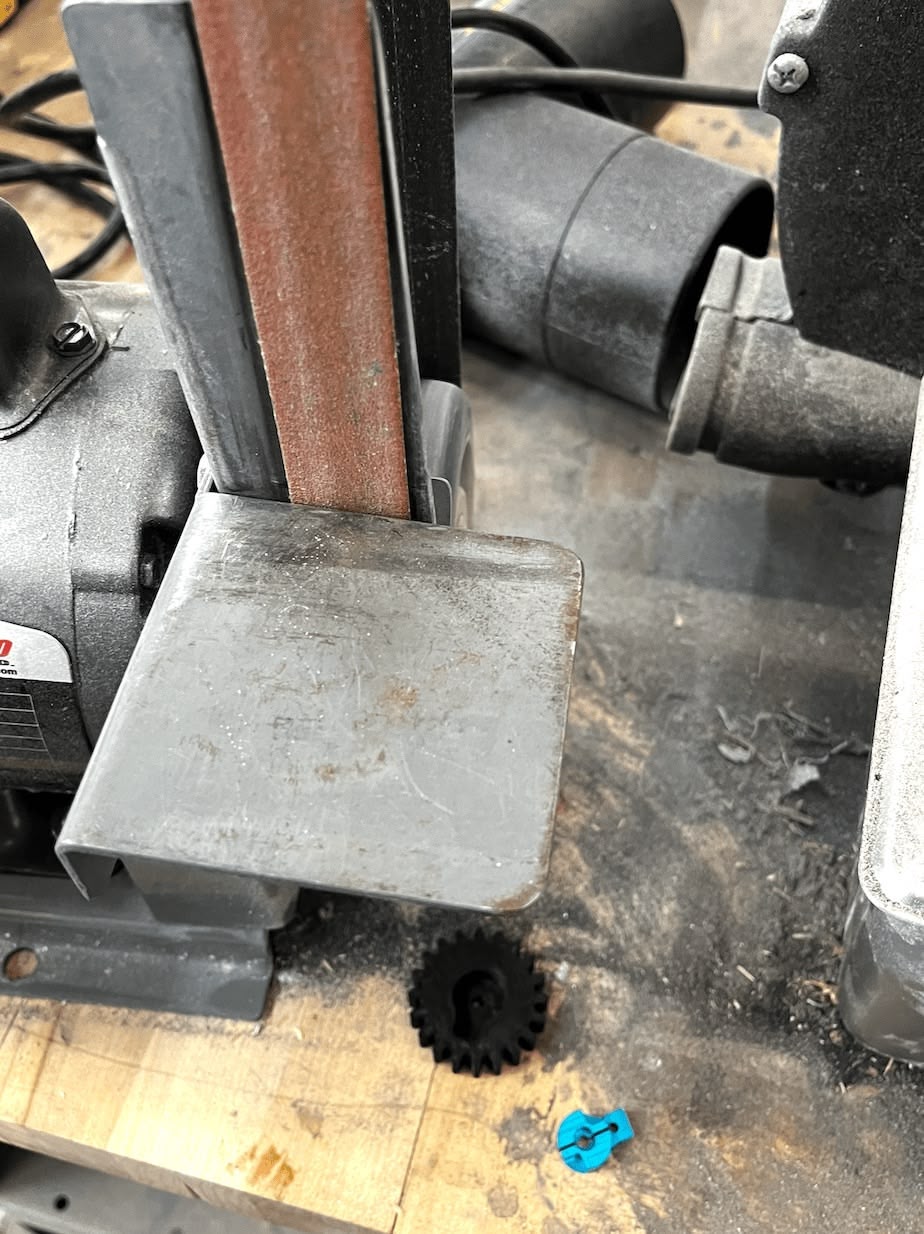
With instructions from Matti, I prepared and installed the servo arms into the 3D printed gear housings. The process had two steps:
Step 1: Sanding the servo arms. The plastic servo arms needed to be sanded down to fit properly into the housings. I used the belt sander for this—fair warning, the friction makes the parts extremely hot! Wear gloves.
Step 2: Heat-setting. Once sanded, I heat-set the servo arms into the 3D printed housings using a soldering iron. Pressing the heated arm into the plastic softened the material and formed a tight bond as it cooled.
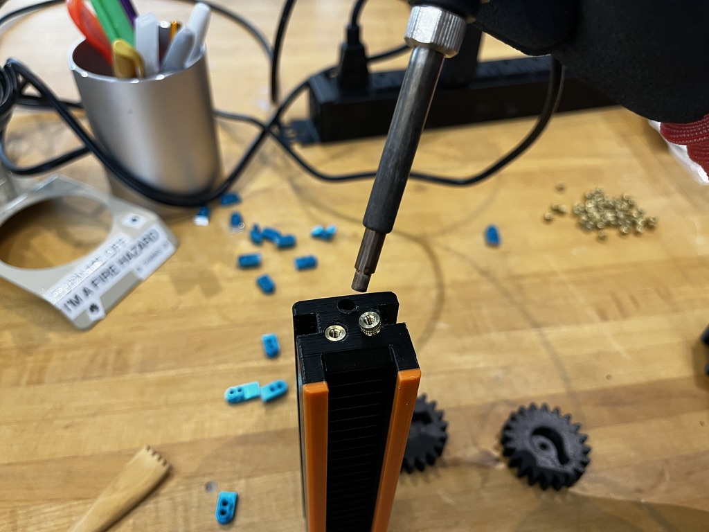
Heat-Setting Screw Nuts
I also heat-set screw nuts into the sliding gear shafts—the "feet" of Neilbot that extend and retract. This was delicate work; the plastic walls were thin, and overheating would warp the entire part.
TODO: Add photo of gear shaft
Unfortunately, these parts turned out to be the weak point of our design. Several gear shafts broke after the first test run—the forces during actuation were higher than expected.
Surgical Repairs
Some of the 3D printed gear shafts came out of the printer with layer adhesion issues. Rather than reprinting (we were out of time), I did "surgical repairs" with the soldering iron—carefully melting broken layers back together and reinforcing weak spots.
TODO: Add photo of repair work
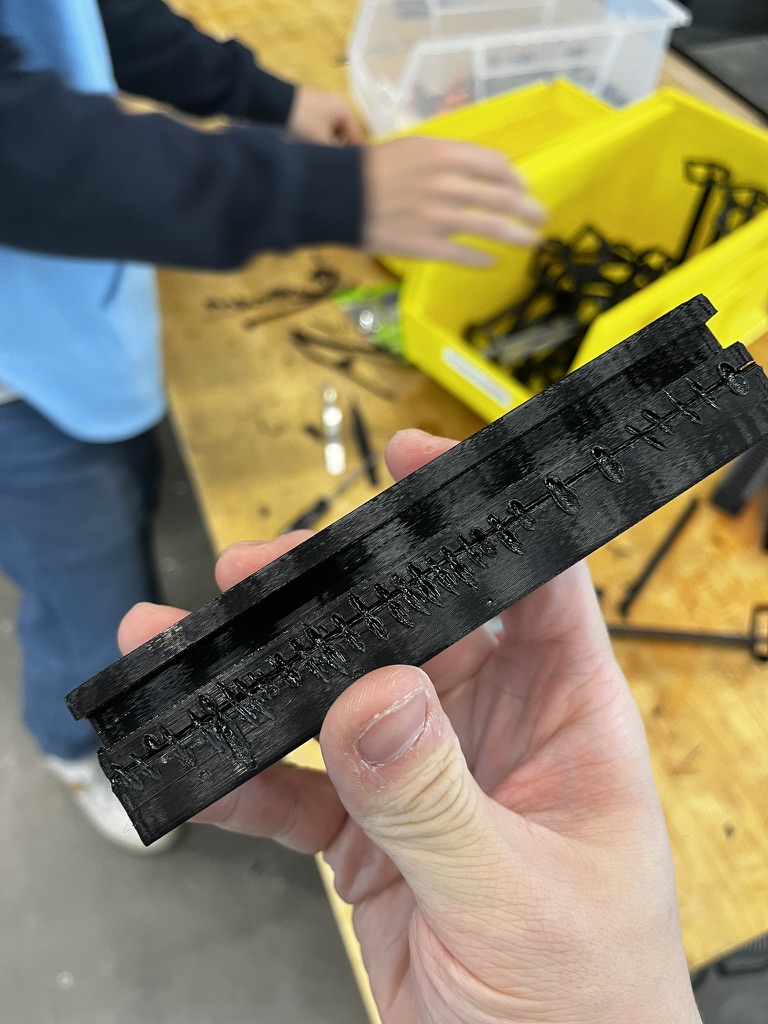
It wasn't pretty, but it worked well enough to get us through the demo.
Final Demo
After an all-nighter of assembly and debugging, we started testing incrementally.
Early Success
With just a few faces assembled, we tested whether the mechanism could actually roll the icosahedron. It worked! The partial assembly successfully tipped itself over.
Full Assembly Test
Once everything was assembled, we tested the servo extension and retraction. The servos worked, but we were testing without load—the icosahedron was suspended in the air rather than bearing its own weight.
The Smoke Test (Literally)
When we attempted to roll the final, fully-loaded version... it didn't move. And then it started smoking, and we had to take it apart to save it from itself...
The mechanical forces required to tip the full icosahedron exceeded what our rack-and-pinion mechanism could deliver. The motors stalled under load and overheated.
The Rescue
Dimitar and Miranda stayed even longer after the all-nighter to salvage what they could. They managed to get half of the motors working again so we could still demo during class. Thank you both!
As a proof of concept and a demonstration of what 15+ people can build in a week, it was still a success—even if autonomous rolling remained just out of reach.
Reflection
This was one of the most intense weeks of the semester. What struck me most was how naturally everyone found their role. When I hit a wall with the quaternion math, I pivoted to building physical infrastructure that unblocked the whole team. When the software was stable, I moved to assembly alongside everyone else.
The testing frame, in particular, was a small investment that paid off repeatedly. Being able to point at a physical face and say "that's face 7" eliminated an entire category of communication errors.
References
- Neilbot Group Documentation
- SparkFun ICM-20948 Library
- Week 4: 3D Printing Icosahedron Kit
- Clear Acrylic Dowel Rods (Amazon)
Design Files
- Testing Frame Components