")
I need to do a few attempts with the bobbin because the clearance was not sufficient.
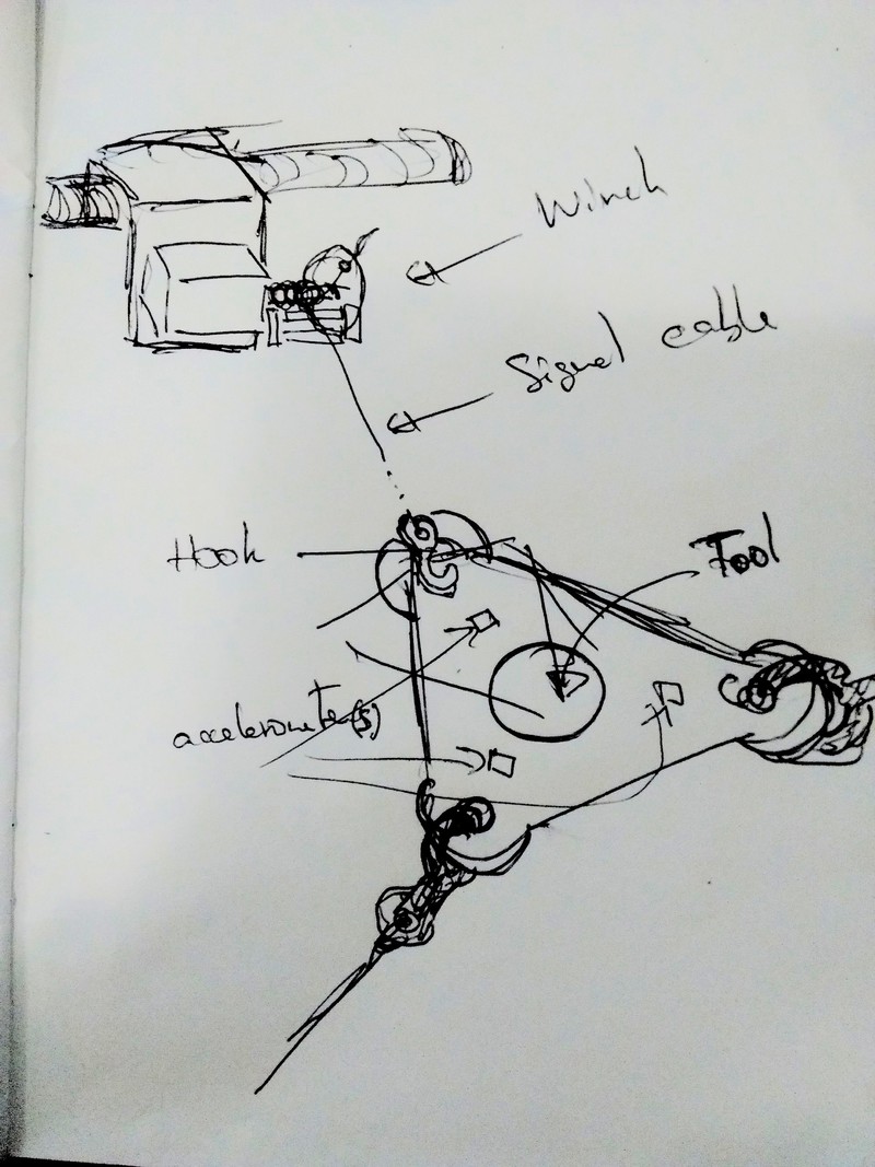
At this point, the components / general steps I have isolated include:
The auto-calibration involves figuring out at which position each axis is. One part of it can be done by the encoder if it is active (and homed) while the user connects the cable to the end-effector plate. It means allowing the stepper to move freely while the encoder is on and records the displacement (possibly with some minimal holding torque).
I can imagine the encoder in two states: (1) fixed positioning (from driver / board) with closed loop correction, and (2) free positioning (user can move it with minimal holding torque) while the encoder records the position but does not correct it. The state could be toggled with a switch on the hook.
Full positioning requires an extra information to be provided, either through accelerometers, or torque / tension sensors to fully determine the position at an instantaneous time point. Another strategy would be to use multiple calibration points to fully determine the system, but this would make it less user-friendly.
The slip ring is an important part if any signal is transmitted through the cables to a board near the stepper motor. It is meant to transfer signals from an element that is spinning (e.g. the cable around the bobbin) to a stationary component that is not (e.g. the stepper motor board). For example, it was used in the 3D printer for Interactive Electromagnetic Devices.
I winding the electric wire around the failed bobbin and discovered that although it would fit (but barely), the multiple layers end up creating lots of elastic energy that is not welcome for the system. I will go with fishing lines that do not stretch, are very strong and are much lighter and smaller.
I printed the bobbin with clearances of 1/128 and 1/256 inches, and both seem to work pretty well. The real test will be when these are loaded.
 and one with 1/128in (left)")
I had lots of discussions with my colleagues in my lab about what types of sensors I should be using for the calibration. This is more complicated than I thought and I didn't figure out an easy setup that would fully determine the system easily yet.
The initial (0,0,0) position would be defined by the user setting up the machine (and possibly clicking on a button to trigger the calibration procedure). At that point, we have three pieces of data (provided by the stepper encoders): the distance from (0,0,0) to the three winches. The system is not fully defined, we need more constraints. Total: 9DoFs if we simplify the winch models and assume single point of exit without caring about the winch and cable orientations.
If we use step movements for each axis, we can measure some of the changes of the system and potentially infer the remaining DoFs. Unfortunately, getting the relative position from (0,0,0) directly does not seem trivial. Can we do it indirectly with sensors? Hopefully yes.
Given lots of thinking and not many good outcomes, I decided to start creating a simulation environment for cable machine using Three.js. This may help get a clearer idea by looking at the system's dynamics.
Created page project for sound-based positioning. The idea is to use sound to do fine localization of components within a machine, which would be very useful to automate the calibration of a cable-driven machine.
I read about Euclidean Distance Matrices or how to precisely find the relative position of nodes when we know their pairwise distances. This means that the project is basically focusing on figuring out the distance between two similar nodes using sound (similar to sonars, except these usually work with echo waves). Piezo-electric components (such as that one) seem to be able to emit and sense sound, but are not necessarily very efficient. I'll be checking these to figure out if it's any use for distance measurement at multiple meters apart. A friend of mine suggested to not have co-located emitters and receivers, but instead use dedicated chips that would have much better properties. He recommended usound but these are in progress, so not for today. He also suggested looking at the InvenSense chips from TDK.
I'll be getting piezo-element samples from Amazon and testing them soon. If they work, perfect. Otherwise, we'll go with distinct emitters and receivers that are located nearby. In that case, we may want the emitter to have some directionality (to be more efficient at transferring sound).
Also ordering samples for speakers and microphones:
The initial idea was to use a piezo element as a co-located speaker and microphone, at a very low cost. I tested one from Amazon and although they can generate reasonable amount of sound, their general sensitivity is much lower. They can easily hear contact vibration such as knocks but I could not get any reading from external sounds that would not be in direct contact with the contact surface. Piezo elements mostly work as contact microphones.
This means I'll probably go with a two-components approach with a specialized mini small speaker located near a small microphone.
I will need to find a reasonable pair speaker/microphone with similar frequency of maximum efficiency.
To do the distance measurement, we need to measure precisely the time at which the signal is received, which means discovering the signal and getting precise phase information.
The first attempt will be software-based chirp demodulation, either using software PLL (several tutorials), or (more likely) simple cross-correlation for chirp matching (since it's much simpler to implement).
Instead of worrying about the nRF52 ADC speed, Jake suggested to rely on digital microphone I2S signals. He suggested this microphone, and that happens to be one that I ordered through Digikey (as an Adafruit board).
V=(PR)1/2=0.56V and I=(P/R)1/2=0.018A.
See P = VI.
Initially, I didn't think about it and just plugged the speaker to an Arduino.
Nothing burnt, but I was likely going above the rated power.
21/2 = 1.4, but it won't help much.
Looking at new speakers, and audio amplifiers since we'll need higher power (i.e. 100mW or even 1W).
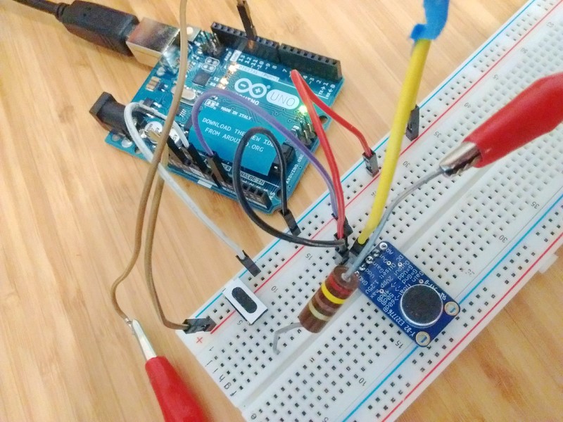
Testing the microphone boards from Adafruit, notably the one with automatic gain control. I went over the accompanying tutorial and wired it as well as the mini speaker (with 250 Ohms in series).
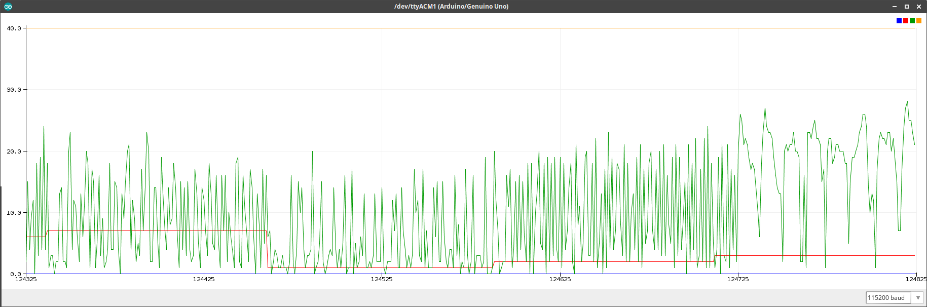
Although the emitted sound is very quiet, we can definitely see the change of frequency in the raw signal (buried with lots of noise).
The plot below shows four different audio samples' instantaneous rates (in green),
the frequency index (in red) out of [0.1, 0.25, 0.5, 1, 1.5, 2, 2.5] kHz,
as well as two constants for the ranges (blue = 0, orange = 40).
Different frequencies definitely show different rate patterns.
The code uses the DDS from Martin Nawrath.
#include "avr/pgmspace.h"

// table of 256 sine values / one sine period / stored in flash memory
const unsigned char sine256[] PROGMEM = {
  127,130,133,136,139,143,146,149,152,155,158,161,164,167,170,173,176,178,181,184,187,190,
  192,195,198,200,203,205,208,210,212,215,217,219,221,223,225,227,229,231,233,234,236,238,
  239,240, 242,243,244,245,247,248,249,249,250,251,252,252,253,253,253,254,254,254,254,254,
  254,254,253,253,253,252,252,251,250,249,249,248,247,245,244,243,242,240,239,238,236,234,
  233,231,229,227,225,223,221,219,217,215,212,210,208,205,203,200,198,195,192,190,187,184,
  181,178,176,173,170,167,164,161,158,155,152,149,146,143,139,136,133,130,127,124,121,118,
  115,111,108,105,102,99,96,93,90,87,84,81,78,76,73,70,67,64,62,59,56,54,51,49,46,44,42,39,
  37,35,33,31,29,27,25,23,21,20,18,16,15,14,12,11,10,9,7,6,5,5,4,3,2,2,1,1,1,0,0,0,0,0,0,0,
  1,1,1,2,2,3,4,5,5,6,7,9,10,11,12,14,15,16,18,20,21,23,25,27,29,31,33,35,37,39,42,44,46,49,
  51,54,56,59,62,64,67,70,73,76,78,81,84,87,90,93,96,99,102,105,108,111,115,118,121,124
};
#define cbi(sfr, bit) (_SFR_BYTE(sfr) &= ~_BV(bit))
#define sbi(sfr, bit) (_SFR_BYTE(sfr) |= _BV(bit))

int ledPin = 13;                 // LED pin 7
int testPin = 7;
int t2Pin = 6;
byte bb;

const uint8_t samples = 25;

int freqidx = 0;
int freqcount = 7;
double freqlist[] = {
  100.0, 250.0, 500.0, 1000.0, 1500.0, 2000.0, 2500.0
};

double dfreq;
// const double refclk=31372.549;  // =16MHz / 510
const double refclk=31376.6;      // measured

// variables used inside interrupt service declared as voilatile
volatile byte icnt;              // var inside interrupt
volatile byte icnt1;             // var inside interrupt
volatile byte c4ms;              // counter incremented all 4ms
volatile unsigned long phaccu;   // pahse accumulator
volatile unsigned long tword_m;  // dds tuning word m

void setup()
{
  pinMode(ledPin, OUTPUT);      // sets the digital pin as output
  Serial.begin(115200);        // connect to the serial port
  Serial.println("DDS Test");

  pinMode(0, INPUT);
  pinMode(6, OUTPUT);      // sets the digital pin as output
  pinMode(7, OUTPUT);      // sets the digital pin as output
  pinMode(11, OUTPUT);     // pin11= PWM  output / frequency output

  Setup_timer2();

  // disable interrupts to avoid timing distortion
  cbi (TIMSK0,TOIE0);              // disable Timer0 !!! delay() is now not available
  sbi (TIMSK2,TOIE2);              // enable Timer2 Interrupt

  dfreq=freqlist[freqidx];                    // initial output frequency = 1000.o Hz
  tword_m=pow(2,32)*dfreq/refclk;  // calulate DDS new tuning word

}
void loop()
{
  while(1) {
    if (c4ms > 250) {                  // timer / wait fou a full second
      c4ms = 0;
      // dfreq=analogRead(0);             // read Poti on analog pin 0 to adjust output frequency from 0..1023 Hz
      freqidx = (freqidx + 1) % freqcount;
      dfreq = freqlist[freqidx];

      cbi (TIMSK2,TOIE2);              // disble Timer2 Interrupt
      tword_m=pow(2,32)*dfreq/refclk;  // calulate DDS new tuning word
      sbi (TIMSK2,TOIE2);              // enable Timer2 Interrupt
    }

    sbi(PORTD,6); // Test / set PORTD,7 high to observe timing with a scope
    cbi(PORTD,6); // Test /reset PORTD,7 high to observe timing with a scope

    // only output the 10 first milliseconds of each second
    // so that we can visualize the difference between multiple frequencies easily
    if(c4ms > 25)
      continue;

    // accumulate samples
    static int lastSample = 0;
    int newSample = analogRead(0);

    //Serial.print(dfreq);
    //Serial.print("  ");
    Serial.print("0 ");
    Serial.print(freqidx + 1);
    Serial.print(" ");
    Serial.print(abs(newSample - lastSample));
    Serial.println(" 40");

    lastSample = newSample;
  }
}
//******************************************************************
// timer2 setup
// set prscaler to 1, PWM mode to phase correct PWM,  16000000/510 = 31372.55 Hz clock
void Setup_timer2() {

// Timer2 Clock Prescaler to : 1
  sbi (TCCR2B, CS20);
  cbi (TCCR2B, CS21);
  cbi (TCCR2B, CS22);

  // Timer2 PWM Mode set to Phase Correct PWM
  cbi (TCCR2A, COM2A0);  // clear Compare Match
  sbi (TCCR2A, COM2A1);

  sbi (TCCR2A, WGM20);  // Mode 1  / Phase Correct PWM
  cbi (TCCR2A, WGM21);
  cbi (TCCR2B, WGM22);
}

//******************************************************************
// Timer2 Interrupt Service at 31372,550 KHz = 32uSec
// this is the timebase REFCLOCK for the DDS generator
// FOUT = (M (REFCLK)) / (2 exp 32)
// runtime : 8 microseconds ( inclusive push and pop)
ISR(TIMER2_OVF_vect) {

  sbi(PORTD,7);          // Test / set PORTD,7 high to observe timing with a oscope

  phaccu=phaccu+tword_m; // soft DDS, phase accu with 32 bits
  icnt=phaccu >> 24;     // use upper 8 bits for phase accu as frequency information
                         // read value fron ROM sine table and send to PWM DAC
  OCR2A=pgm_read_byte_near(sine256 + icnt);

  if(icnt1++ == 125) {  // increment variable c4ms all 4 milliseconds
    c4ms++;
    icnt1=0;
   }

 cbi(PORTD,7);            // reset PORTD,7
}
I then went to look for FFTs:
Reading about BLE and porting the Arduino code to Adafruit BLE boards with the nRF52. Adafruit has a Desktop BLE application written with node.js. There seems to be interest in doing that directly in the browser. This might be possible soon with WebBluetooth.
I have been trying to port the DDS to the nRF52 and this was not very successful.
I seem to have a few issues with PWM in hardware.
The first part is to get a way to handle the TOP value from the RAM, which I got to work in a sequence, but it's buggy.
I can use the PWM_DECODER_LOAD_WaveForm mode so that the three first outputs of a channel use their RAM value for comparison, and the last one becomes the TOP value,
but I can't get to modify that value afterwards, or even just to have a sequence with alternating values for this TOP value.
On top of that, there seems to be a random output inversion which many have mentioned on nRF52 threads, but none seem to apply since I'm using the nRF52 board from Adafruit, and only the hardware PWM, not the PPI or SoftDevice versions.
static uint16_t PWM_vals[] = {
  2000, 0, 0, 6000
};
for(int i = 0; i < 4; ++i)
  PWM_vals[i] |= 1 << 15; // to undo the inversion

NRF_PWM0->PSEL.OUT[0] = (A0 << PWM_PSEL_OUT_PIN_Pos) | (PWM_PSEL_OUT_CONNECT_Connected << PWM_PSEL_OUT_CONNECT_Pos);
NRF_PWM0->ENABLE = (PWM_ENABLE_ENABLE_Enabled << PWM_ENABLE_ENABLE_Pos);
NRF_PWM0->MODE = (PWM_MODE_UPDOWN_Up << PWM_MODE_UPDOWN_Pos);
NRF_PWM0->PRESCALER = (PWM_PRESCALER_PRESCALER_DIV_32 << PWM_PRESCALER_PRESCALER_Pos);
NRF_PWM0->COUNTERTOP = (PWM_top << PWM_COUNTERTOP_COUNTERTOP_Pos); //1 msec
NRF_PWM0->LOOP = (PWM_LOOP_CNT_Disabled << PWM_LOOP_CNT_Pos);
NRF_PWM0->DECODER = (PWM_DECODER_LOAD_WaveForm << PWM_DECODER_LOAD_Pos) | (PWM_DECODER_MODE_RefreshCount << PWM_DECODER_MODE_Pos);
NRF_PWM0->SEQ[0].PTR = ((uint32_t)(PWM_vals) << PWM_SEQ_PTR_PTR_Pos);
NRF_PWM0->SEQ[0].CNT = ((sizeof(PWM_vals) / sizeof(uint16_t)) << PWM_SEQ_CNT_CNT_Pos);
NRF_PWM0->SEQ[0].REFRESH = 0;
NRF_PWM0->SEQ[0].ENDDELAY = 0;
NRF_PWM0->TASKS_SEQSTART[0] = 1;
I also tried to use the NRF_PWM0->EVENTS_PWMPERIODEND event to update the RAM information, but that was never triggered.
So I still have some way to go before I can get interesting chirps with the nRF52.
Also, I tried to use a sequence of a sine directly, and I passed it through an audio amplifier from Adafruit, which I then gave to a 1W mini-speaker, and the result is quite loud! At least I know that I have the speaker components, I just need to get a reasonable chirp.
Unfortunately, I can't just store the whole chirp in memory because (1) the lowest PWM clock is at 125kHz, and (2) the nRF52 only has around 64kB of RAM. Given the lowest clock, a 1 second sequence would use a 125'000 16bit storage, which the chip doesn't have. Half a second is still not possible because of other libraries. Considering that we want to use a soft device for bluetooth on top, as well as the receiving part on each emitter, we can't rely on having the whole chirp in RAM.
I figured out the issue with my events not being triggered. I changed my code with two modifications:
NVIC_SetPriority(PWM0_IRQn, 0); //low priority
NVIC_ClearPendingIRQ(PWM0_IRQn);
NVIC_EnableIRQ(PWM0_IRQn);
export "C" { } when coding in C++.
After talking with Jake, I figured out that EasyDMA transfer for WaveForm PWM is only triggered when setting the start task. This does the trick!
#ifdef __cplusplus
extern "C" {
#endif
void PWM0_IRQHandler(void){
  other += 1;
  // check the event is a period end
  if(NRF_PWM0->EVENTS_PWMPERIODEND != 0){
    NRF_PWM0->EVENTS_PWMPERIODEND = 0; // clear interrupt
    other += 2;
    // reset PWM value and top
    if(other % 2){
      PWM_vals[0] = 150 | (1 << 15);
      PWM_vals[3] = 300 | (1 << 15);
    }else{
      PWM_vals[0] = 300 | (1 << 15);
      PWM_vals[3] = 600 | (1 << 15);
    }
    // update DMA
    NRF_PWM0->TASKS_SEQSTART[0] = 1;
  }
}
#ifdef __cplusplus
}
#endif
I can thus use the EVENTS_PWMPERIODEND to easily generate any kind of waveform
and this should simplify a lot the DDS implementation for LFM chirp generation.
With lots of debugging, I ended up getting a working DDS using this IRQ handling strategy. Furthermore, by brute-force frequency computation (thanks to the FPU), I can update the frequency in the IRQ. So here is the chirp! The one below is a linear chirp from 500Hz to 2.5kHz over 1 second.
The current DDS implementation is brute-force computation, but fortunately runs just within the PWM period (at around 32us). When not updating the frequency, the timing information runs at 13us. I also fine-tuned the reference frequency by measuring it on the oscilloscope. This makes it quite more precise as a continuous 1kHz sine with the theoretical clock frequency gives me an output sine frequency around +/-5Hz, whereas fine-tuned, it gives +/-0.5Hz (10-fold better!).
void PWM0_IRQHandler(void){
  // check the event is a period end
  NRF_GPIO->OUTSET = 1 << A1;
  NRF_GPIO->OUT ^= 1 << A3;
  if(NRF_PWM0->EVENTS_PWMPERIODEND != 0){
    NRF_PWM0->EVENTS_PWMPERIODEND = 0; // clear interrupt

    // time information
    static unsigned long chirp_counter = 1;

    // local time
    double dt = chirp_counter * chirp.ref_period;

    // chirp on/off
    if(dt < chirp.duration_on){
      // ~30us
      // compute current linear frequency
      double f = chirp.f_start + chirp.f_delta * dt / chirp.duration_on;

      // 32bits phase accumulator
      unsigned long tuning_word = chirp.n_samples * f / chirp.ref_clk;
      chirp.phaccu += tuning_word;

      // /!\ do not assign directly tuning_word expression
      // chirp.phaccu += chirp.n_samples * f / chirp.ref_clk;
      // this does not work!
      // the compiler messes up the type conversion !!!

      // frequency debug
      static uint8_t last_idx = 0;

      // use most significant 8 bits as frequency information
      uint8_t sine_idx = chirp.phaccu >> 24;
      if(sine_idx < last_idx){
        NRF_GPIO->OUT ^= 1 << A2; // toggle to get period / frequency
      }
      last_idx = sine_idx;


      // update duty cycle from sine table
      chirp.cycle_duty = sine256[sine_idx];
    } else {
      // 13us

      // out of chirp
      long current = micros();
      if(current + chirp.ref_period / 2 >= chirp.start_us + chirp.duration){
        // we should restart chirp on next iteration
        chirp.phaccu = 0;
        chirp.start_us = current;
        chirp_counter = -1; // will be overflowed to 0
        // debug signal
        NRF_GPIO->OUT ^= 1 << A4;
      }
      // off-chirp
      chirp.cycle_duty = 0 | (1 << 15);
    }

    // update DMA
    NRF_PWM0->TASKS_SEQSTART[0] = 1;

    // update local time
    ++chirp_counter;
  }
  NRF_GPIO->OUTCLR = 1 << A1;
}
One tricky part that took me a while was to realize that the compiler generated a very different result for the two following computations (seemingly the same) of the new phase accumulator:
// wrong:
chirp.phaccu += chirp.n_samples * f / chirp.ref_clk;

// correct:
unsigned long tuning_word = chirp.n_samples * f / chirp.ref_clk;
chirp.phaccu += tuning_word;
The first version doesn't compute the correct result because the phase accumulator has type unsigned long
whereas the new tuning word expression is a double.
When using +=, the compiler unrolls it into a full RHS expression that includes the phase accumulator,
which gets cast to double, so the two expression are actually quite different.
The first casts the final phase accumulator back, whereas the second casts the tuning word directly.
The full code can be found here.
Update: I went on to reduce the runtime in the IRQ (which was very close to the PWM frequency). The optimization included removing some unprecise time computations to use the default microsecond timer instead. This also resulted in fewer floating pointer operations. Now, the code runs in 15us on chirp, and 9us off chirp. Find the optimized code here.
Next is the chirp demodulation with I2S, Automatic Gain Control (AGC) and PLL in software.
I've been trying to get I2S working with the nRF52 but couldn't see any clock signal out. I saw a few people having issues with I2S in master mode for microphones on it, and notably this github repository. I am only interested in mono channel, so I may not be affected by the issue, but looking with an oscilloscope, I don't see any signal with the default examples.
I'll try debugging further, and if nothing comes out, I'll revert to using the ADC directly for reading the microphone data since I have already got that working.
I Went over many papers for path planning, most of which came from the Computer-Aided Design journal.
So, I think I found the problem I was dealing with. The base code I used to narrow it down was this one that generates a sine wave with I2S.
This works, and switching to the Mono/Left setting still works with a reasonable master clock at around 3MHz.
However, if I try to use a single RAM data point, it does not work anymore.
Basically, I2S requires a buffer size of minimum 2 to work properly.
I guess this has to do with double buffering and Easy DMA.
Unfortunately, I am now seeing the issues that others have faced. Especially this thread explains that the current microphone (and most I2S ones) won't work with the nRF52 because of the number of bits (24) not being correctly supported. The person who went through the debugging eventually went with using PDM instead. There's another brave soul who decided to hack it and use I2S in slave mode, while generating the master clock using PWM. I will check that hack, and if it works out of the box, stay with it, otherwise I'll give up on I2S and use a PDM microphone.
I decided to avoid the hack and test PDM directly, and it works out-of-the-box. Unfortunately, the gain control here was not sufficient (only software). I realized that without gain control, I won't get much of the receiver signal. This is using the PDM breakout board from Adafruit.
And then using directly the nRF ADC to sample from the MAX9814 board with AGC, we can much more clearly see the actual chirp signal. This means we'll need automatic gain control in hardware.
Those videos are testing 80cm away.
It degrades substantially when going farther, except for the AGC one, where even at 2m the signal is still visible.
However, I may still need to use a different speaker.
Interestingly, I tried this 0.2W 8Ohm speaker, and the sound was much louder.
However, with the audio amplifier, I'm actually running it beyond its power rating.
Did some stuffing (6 stepper driver boards) under the supervision of Jake.
Unfortunately, I'm away this week to CHI, so nothing important will happen.
I decided to analyze the sound signal to check whether I had any chance at demodulation before going farther. My first attempt was done on the ADC result signal and had weird slow-down periods. The spectrogram is not nice. We can see the linear chirps, but it's not linear, it goes up, then down and back up... Compared to ambiant noise, it's clearly in the good direction, but I am thinking of a sampling issue here.


I decided to capture the signal with an oscilloscope before it gets processed by the ADC of the nRF52.
I used an Owon HDS1021M, and did some fixing over these drivers.
The owondump code had a bug for me where the timestamp was 0, and thus dumping never ended.
I fixed it by checking for the special case where decoding a null timestamp (see modified source and original header, compile with gcc -o owondump owondump.c -lusb).
Below is a comparison of the signal at the output of the AGC microphone, before being read on the nRF52, as well as the signal from the nRF52 using the ADC to read the previous signal.

There is likely a sampling issue. Unclear whether from ADC or sending the signal over UART. This leads to bad spectrum information. In fact, the raw signal has a really nice linear spectrum trace (with quite a few harmonics, but still).


The first problem is definitely a sampling issue, because over a one second chirp, I only get around 1000 samples, when the signal frequencies go from 500Hz to 2500Hz. I need at least 5000 samples to be meaningful!
Note: I am taking the spectrogram of the normalized signal. Here, normalized refers to normalizing so that the mean (from the 500 past samples) is at 0, and the amplitude (half range from past 500 samples) is 1. Without normalization, the spectrograms would have most the energy at the base frequencies.
I improved my serial communication (less data), and increased baudrate to 230400, and finally used a bitstream instead of sending ascii data. This resulted in a much higher sample rate beyond what necessary (10k samples per second). Now I get an expected spectrogram, similar to that from the oscilloscope, with some shift because I'm actually sampling twice as fast as what the oscilloscope would allow for a second of samples stored in memory. The frequency sweep is quite nice, but there are a few harmonics. Hopefully these won't hurt. Next is the PLL.


I got three boards from Jake, and he eventually took care of programming the router which he gave us too.
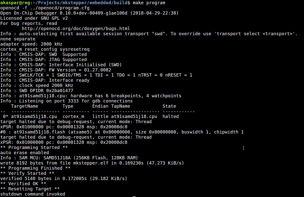
As for programming the stepper board, I started trying with OpenOCD from Linux and quickly found that it was not working.
The issue seems to come from ATSAMD51 boards (there's the driver at91samdXX available), not behaving the same way
for memory programming.
After an evening of debugging, I resolved to installing Windows 10 in VirtualBox and trying first to program with Atmel Studio. There are a few tweaks, namely the need to upgrade the firmware of the Atmel ICE from within VirtualBox. This is solved as shown there. It requires adding USB filters to let the debugger through the virtual environment. In fact, it captures it, so you cannot use it both on Linux and Windows at the same time of course...
This worked, and I got it to work. I then went back to Linux and tried programming the binary files from Jake. This was still not working. I quickly found the existence of a patch that supposedly takes care of it. I then installed openocd from sources and applied that patch.
And it works!
I pushed the documentation on how to do that in a openocd branch on mkstepper.
See there.
I also added information on how to build with make, program and debug there.
Now to trying with the router and having a small light switch. My packet is the following:
packet 0,3,ptr,end,128
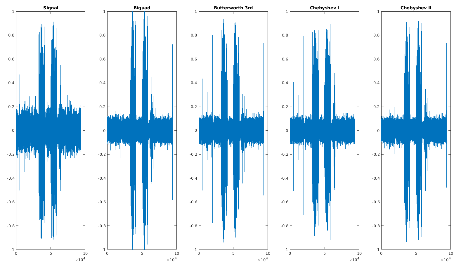
Tried some PLL implementation and was shocked by how the parameters are hard to set correctly. Then I decided to try cleaning the original signal a bit. By looking at the FFT of my noise, I can see that most of it was below 500Hz, so I'll be using a highpass filter to only keep what's above. I tried with biquadratic, Butterworth and Chebyshev (type I and II) filters. It seems that I'll go with Butterworth for now, and third order is easy enough (2x4 coefficients IIR).
As for the PLL, I am thinking of recording a simpler chirp. Right now, the frequency range is very large (500Hz to 2.5KHz), and the PLL doesn't seem to lock. I'll go with something closer to the peak efficiency of the receiver/emitter pair (i.e. at 1.5KHz) with small band. Of course, the higher the change of frequency, the more precise the result, but I don't have any result yet...
Lots of attempts at tweaking the PLL, and I realize that having a linear chirp might be overkill. In theory, it's nice, but practice will be hard to implement because of the frequency sweep. If the two signals had no phase shift, it could work well, but because we're looking to find explicitly the phase shift, it has lots of complications. I thus decided to go with Frequency-Shift Keying. I might use more than just the binary (or unary really) version of it.
Tweaking the PLL parameters is an art. It took me a while to understand some of their behaviours, so I'll document what I found here. The code for the results below is there. But before that, here are some results with an ideal processing pipeline where I'd know the amplitude decay of the sound (which we don't given that we're looking for the distance), and assuming that we can normalize the signal and filter it with great precision (here butterworth 3rd order). I tried it first on a audio signal using a signal chirp frequency at 1.5kHz:

Then looking at the less ideal variant of doing automatic normalization (using 500 past samples), we actually get something really similar in terms of PLL lock, but the PLL output is very noisy. This means that we wouldn't do a good job at outputting the locked frequency. Except we don't care about that since we're not going with linear chirps anymore (I had a reason).

If we use a biquadratic lowpass filter (2x 3 coefficients IIR, cutoff at 1kHz), then we could get a nice frequency output.

And then, if we apply all of that on the chirp-modulated signal, we do get basically an output for the small period the chirp is around 1.5kHz. The PLL is still stable.


If we had lots of computing power, we could use many PLLs in parallel: one for each frequency that is generated within the chirp, namely 33 in our example. The other ideal option would be to use a PLL that locks on the chirp signal itself, but then we need to do it multiple times, or have the frequency sweep only start on lock detection. This is possible, but probably not trivial because generating the chirp is already computing intensive, so generating the reference and a PLL at the same time might be too hard. I'll focus on FSK for now. Maybe 3-FSK.
Now about the parameter tweaking:
The next trick is going to be to actually have that not in Matlab but on the microcontroller and in realtime, specifically because many of these operations are floating point multiplications, which take a considerable amount of computing time. Not having to filter several of the signals will help. As for the required lock filters, we'll probably go with biquadratic filters, using fixed point operations. Fortunately, there are Arduino libraries for fixed-point arithmetic, notably with Q numbers such as that one.
I decided to implement BFSK coding for the chirp to have better average accuracy. And I started to realize a few issues at the chirp boundaries. The first one is that when using two different frequencies, we get a few harmonics. See the spectrum below for BFSK at 750Hz and 1500Hz (I tried first 1kHz and 1.5kHz but the total harmonics were even more troublesome).


One other issue are peaks at the frequency transition. I never looked closely at the transition region yet, and this is however quite important. The issue for two frequencies is that the second one gets highly attenuated because of the peaks and the automatic gain control circuit. This cannot really be removed, so the peaks are quite of an issue since they mess up the amplitude.

Fortunately, if we use narrow bandpass filters, we can remove a lot of these problems. However, now that it locks correctly, I am starting to see the reason why I think FSK won't work. The PLL takes too long to lock.

This delay can be mitigated by reducing the lowpass filtering (right now cut above 10Hz) and extending to larger variations (e.g. 100Hz). This however leads to spurious locks in the noise region. Because the delay seems somewhat constant, I started figuring out the cost of it and whether the uncertainty was bad. And that's where I raised an issue with FSK...
I think I looked at that problem early on, but I skipped it because linear frequency modulation technically solves it. Here the issue with FSK is the presence of the lowpass delay. In the faster locking at 100Hz for the PLL lock, forgetting the problem of new noisy locks, I still counted around 50 samples of delay. But what is that? At a sampling of roughly 10kHz, this is 5ms. Sounds travels at 343m/s, so this means 1.7m of uncertainty!
Let's think back about the goal: precise localization. Assuming velocity at 343m/s, we have:
| Time uncertainty | Range uncertainty |
| 1 us | 343 um |
| 5 us | 1.72 mm |
| 10 us | 3.43 mm |
| 100 us | 3.43 cm |
| 1 ms | 34.3 cm |
| 5 ms | 1.72 m |
For reasonable purposes, we need to be at most at 1us uncertainty. In fact, to get useful calibration, we probably want to be closer to 100us! Our target is 100us uncertainty (given the size of speakers/receivers).
Now, regarding the sampling, we're mostly fine with the current setup because I get samples to the computer at around 10kHz which is a 100us period. Of course the real thing will be on the IC.
Can we do better? To make sure I looked up the SAADC specs, and we can run it (in 8bit resolution) at up to 16MHz/80 which is 200kHz. This is great, it would be a period of 5us (1.72mm). However we're far from that with our 50 samples of discrepancy above (i.e. 1.7m!).
For frequency locking, we need to get a very precise lock and very quickly, which seems hard without getting noise issues. The reason I had hope initially was because the linear chirp can average the error over time: any single datapoint after the initial PLL lock provides a valid measurement of the initial time of the chirp. By having a long chirp, we might thus get away with some of the errors.
On the other side, FSK uses binary (or N-ary) frequency shifts that all get the same lock problem. PLL keeps working well if the frequency transitions are continuous. FSK unfortunately uses discontinuities, and thus keeps reintroducing the lock problem.
So at this stage, I'm considering (2+1) approaches:
For some reason, I had not considered pulse coding yet. Still, it seems like a simpler alternative. The main unknown are:
Before diving with pulses, I'll check whether the current setup can be made to work with linear short-range chirps. This will require: (1) testing whether we can get a reasonable lock over the whole sweep with a single reference frequency, and (2) checking the resulting accuracy (with a filter on the PLL output to aggregate correct chirp information).
One idea for the chirp lock is to still sweep the reference, but by using a known delta on the tuning word (since the tuning word changes at known rate). This should be done on the emitter too, to reduce computations below 10us (by avoiding floating operations completely).
Then we can envision doing sampling at 100kHz which would allow a much faster and better locking mechanism. Although then it wouldn't make sense unless we increase the PDM sampling frequency to equivalently 100kHz which might degrade the wave quality. We'll see if it is needed.
I tested PLL with a chirp from 1kHz to 1.1kHz and got settings to lock onto it for the whole chirp with a single reference frequency at 1.05kHz.

I then focused on the internal signals, namely the two locks (each at 90deg from the other, in dotted blue and gray) and the PLL output (continuous darkblue / purple). As we can see, interestingly, the two locks switch depending on whether the real frequency is below or above the reference frequency. However, the switch is not very clean, and using that for the offset calculation wouldn't benefit from a long chirp. I also tried to use frequency steps instead of a continuous modulation. It works, but I am not sure it can really help (besides giving us an estimate of the lock time).


The locking mechanism is basically all behind one trigonometric formula:
Thus by multiplying our input signal with a reference signal at fixed frequency (here our mid-frequency at 1.05kHz), and then lowpass-filtering the result, we have a signal that only contains a mix of the phase and frequency offsets:
This offset signal can be used for two purposes: (1) first to cancel the phase offset so as to align two signals, and (2) then to actually output frequency information. With the chirp that has continuously varying frequency, there is a tradeoff between getting good phase lock and correct frequency output. However I realized that by using two ramps (one up and the other down), then we don't need to get accurate frequency measurement, we only need to get a good estimate of the frequency ramp switch.


Here the boundaries (where the locking is uncertain) don't matter. Every sample gives us a datapoint that can be accumulated to measure the chirp center (one ramp down intersected with the other going up). And the longer the chirp, the more samples, so the more accurate the estimate! I'll be going with this method for range measurement.
I implemented an online algorithm for detecting the chirp beginning using (weighted) moving average for estimation of the slope parameters. This is slightly tricky and the result is that I am not sure whether we are as precise as I expected. The weird part is that their is a consistent slopt difference between the decreasing chirp and the increasing chirp. The slop of the increasing chirp seems to vary less, but unfortunately I didn't find a way to use a single slop as of now.

The discrepancy between up and down chirp slopes is a bit worrying (i.e. I assumed they would be the same - modulo the sign). I also tested using the zero crossing of the PLL output signal and assuming both would be at 1/4 and 3/4 of the chirp. This seems to be quite close to what I get by slope intersection: within 10 samples, which sadly at 8kHz sampling means 40cm. The hope is that by sampling 10 times faster, that may be only 4cm uncertainty.
At this stage, I don't think I will get any improvement unless I test on the nRF52, so the next stage is porting it and testing the real-life accuracy. If it doesn't work, I'll use pulses, which seems to have a simpler variant as done in this paper, except that they did it with ultrasonic sensors pulses at 40kHz.
This is the last week! Still lot to do! Arghk.
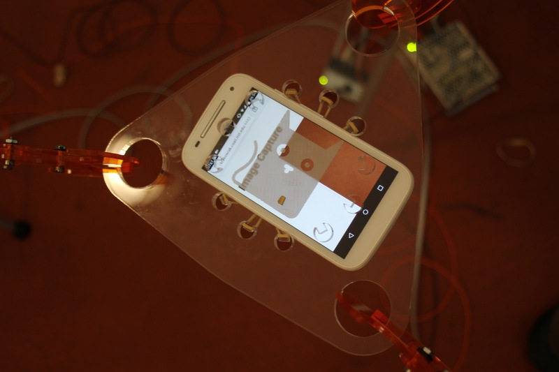
After looking at the Image Capture API, I decided to implement my scanner using
a smartphone that would be connected to my server.
Locally, I use Node.js with WebSockets and HTTPS.
HTTPS is required for accessing the MediaDevices on Chrome.
localhost is the only exception, but since I'm using a client/server with the client on a different system (phone), I need that.
Fortunately, it's reasonably easy to do in a hacky way.
From the terminal, it serves the files over HTTPS, and can send commands to the clients.
Right now, there's just image to acquire an image from every client and save that locally.
Later, it'll also talk to the stepper motors and move the machine.

")
I implemented normalization slightly differently by using a moving average (similar) for the mean-centering, and a min/max finding algorithm for the range that uses an accumulation map to count how many elements are of a given value for our interval. This means that when the signal changes smoothly, the tracking doesn't incur much. When it changes abruptly, the tracking can take slightly longer. The signal is correctly normalized!
Then I realized while timing the sections of my code that my assumption of fixed point vs floating point usage was wrong.
I decided to use a library for fixed point computation because my experience had been bad with floating point operations,
but now I realized that my fixed point implementation was slower than a simpler usage of float.
The whole normalization takes around 8 to 13 us using fixed point computations,
against 2 to 8 us (the median is closer to 2)!
The experiment code is in embedded/acoloca/acoloca.ino with the precompiler switch USE_FIXED_POINT.
However I'm only keeping it in this tag commit.
I started unrolling the PLL code naively with floating point operations. Additions and multiplications are negligible (~100ns each). Lowpass filtering is also reasonably fast (~0.5us each). However, the hit is with cosine and sine computations. Done directly, they cost around 50us each!
The good news is that replacing that with a phase accumulator (with a variable tuning word) reduces it to around 400ns, which is great. Compare:
// direct fp computations
ref_time += SAMPLE_PERIOD; // ~100ns
ref_phase = REF_OMEGA * (ref_time + pll_integral); // ~100ns
ref_signal = sin(ref_phase); // ~50us !!!

// phase accumulator with sine table (total ~400ns)
tuning_word = TUNING_DELTA * (1.0f + pll_loop_control);
ref_phase_accu += tuning_word;
ref_signal2 = fsin256[uint8_t(ref_phase_accu >> 24)];
I finally finished the port with almost just copy and paste from Matlab. The good news is that now the whole PLL loop takes 4us. The signal is probably less precise, notably because of:
But the good news is that the PLL still successfuly locks onto the chirp!
For now, I'm going with the simplest: finding the zero-crossing of the PLL output, and using the two detected ones, I get the center time. This was quick and painless.
This took MUCH longer than I expected. First, the SAADC of the nRF52 has quite a lot of parameters, but secondly, its main mode of interest (or at least I though) using continuous sampling cannot do the job I want because it seems to work similarly to PWM where the module needs to be restarted after the DMA buffer is full. With a single-size buffer, I can trigger the start/sample from the interrupt, but the sampling rate varies a lot.
The main solution came from this post that uses the Programmable Peripheral Interconnect module to trigger the ADC restart/sampling using the event of a timer. Unfortunately, I couldn't get to 100kHz initially with this strategy for some unknown reason. I could go only to 60kHz. Using a timer at 100kHz got me 33kHz only, there's a sweet spot at 60kHz after which it seems that starting the ADC module takes too long and shifts the sampling to a following timer interrupt.
I then tested direct analogRead calls, getting only around 30kHz, but using the whole CPU time (so basically useless).
I also tested the same but only initializing the SAADC once and using the calls to read like analogRead, but without the configuration,
which gave me 50kHz, but again with full CPU usage.
Finally, my colleague suggested using PPI but not with a timer, and instead by using the NRF_SAADC->EVENTS_END event to trigger the next start/sample events.
This gets me the highest sampling rates with no CPU time.
By changing the ADC's acquisition time (TACQ: 3us, 5us, 10us ...), I can vary the effective sampling rate (but precision varies).
| Method | Events | TACQ | Highest Frequency |
| PPI | SAADC End | 3us | 217 ± 17 kHz |
| PPI | SAADC End | 5us | 96 ± 2 kHz |
| PPI | SAADC End | 10us | 64 ± 2 kHz |
| PPI | Timer1 | 3us | 60 ± 2 kHz |
| Interrupt | SAADC End | 3us | ~50 kHz (large deviations) |
optimized analogRead() | - | 3us | 50 kHz (full CPU) |
default analogRead() | - | 3us | 33 kHz (full CPU) |
We assembled the hardware for the stepper boards with Andy and did some crimping and debugging for the stepper board. The first main issue was to figure out that we need to reset the board while it's powered to allow the initialization of the stepper driver. Before that, it was not drawing any current or holding anything. Now it does hold very strongly, but we haven't been able to make it move in a desired way. We're powering it at 12V. The current goes to 0.17A.
By increasing the voltage to 19V and then holding reset, it does move continuously, although in a very shaky way.
I looked at the spreadsheet and it seems that we're running with two signals: step (up/down signal) and direction (positive/negative). I looked further at the initialization settings, and found that the only major possible change for the current is to change its scale. The current one is set for 12/32, so maybe we are not using enough current (or too much and the guarding algorithms prevent it). Or maybe there's another problem.
Update: after the class, I went downstairs with Jake and we tested my board + stepper and they worked all well given correct step numbers. We misunderstood the step speed and acceleration values to be in step per second instead of per minute!
Back in my lab, I tested all the four boards I have, and found that using my linux machine to communicate would not work whereas using my macbook would work. This is odd because the communication still works with my linux machine. I can program it, I can send commands and read packets back. But I cannot send blocks that get "interpreted". This is very odd, but given that I'll be using my laptop to run any final demo, this is all fine for now. Andy was not as fortunate, out of three boards, one doesn't program, and the two others didn't manage to move the stepper motors consistently. They can move abruptly the first time, but not after that unless it is reset.
For the video above, I sent the following packet (three times).
packet 0,ptr,end,block,20000,1500000,60000,2000,1900
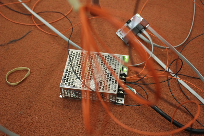
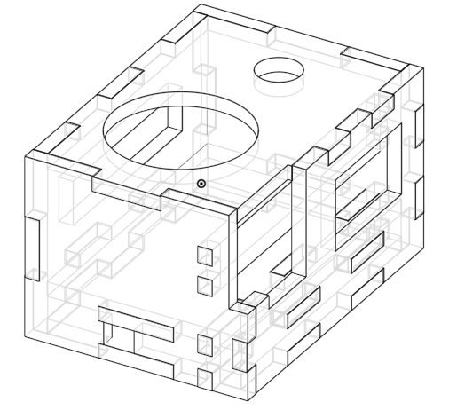
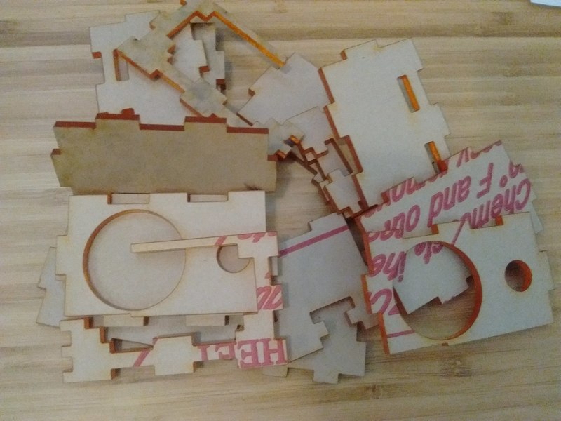
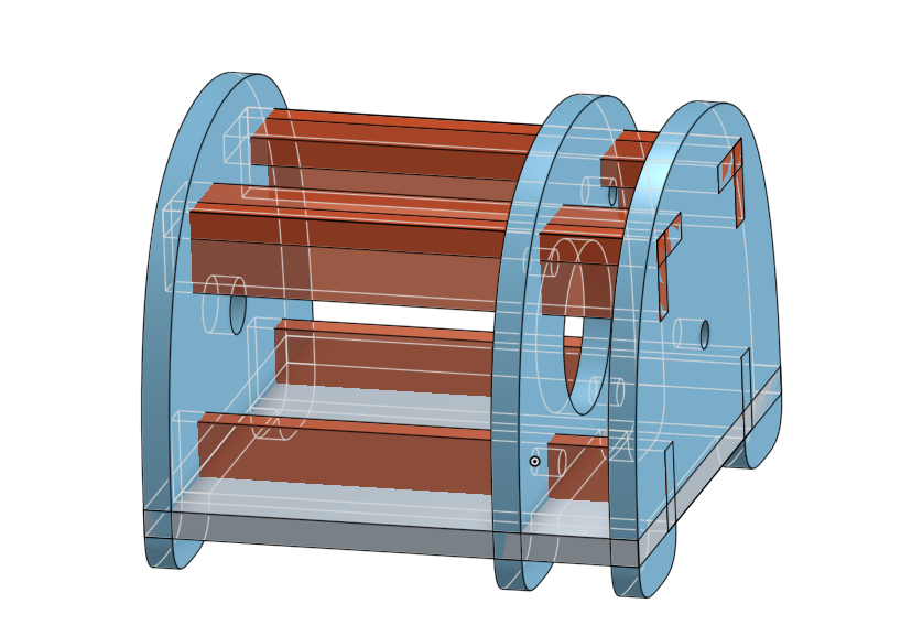
I decided to laser cut a box for all the components making up the acoustic setup. I designed it on OnShape. The two main feature scripts I use for laser cutting are:
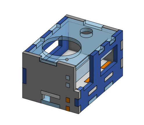
This took several iterations, first to get a good acrylic snap (used a kerf of 0.25mm with 1.25mm sheets). And then, packing the components with jumper cables was harder than expected. I documented the dimensions manually and tried multiple variants considering mostly the 1200mAh Lithium Ion battery, the nRF52 board and the 0.2W speaker.

Since the nRF52 board only has one ground pin (but fortunately 2x 3V pins), I created mini-wire multiplexers by shorting the pins of male headers.

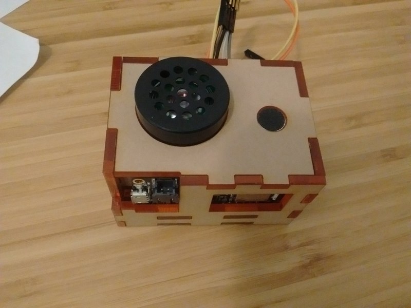
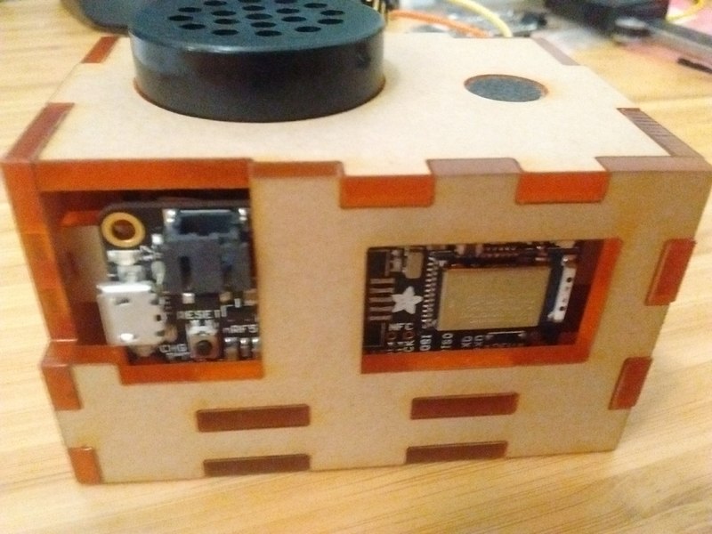
As for the box, it went through having too brittle sides which needed to be widened, to having components at the bad position and blocking each others (most of them are at highly constrained regions with no room for movement). Finally, with the cables I currently have, the wiring would not fit inside the box, so I created an outlet to let the wires do their mess outside of the box. This is not ideal, but it will do for now.
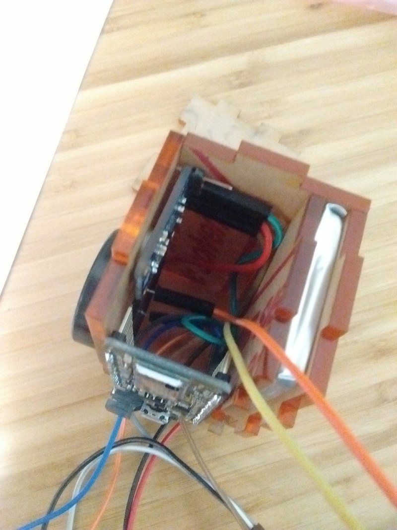
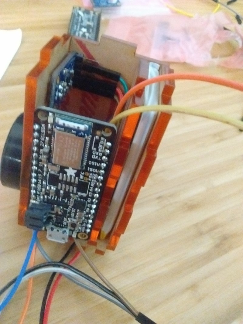
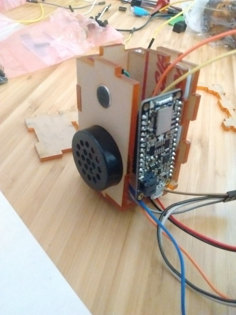
And we have our little package. The size of the final box is 67.35 x 49.025 x 39.525 mm (length, width, depth).
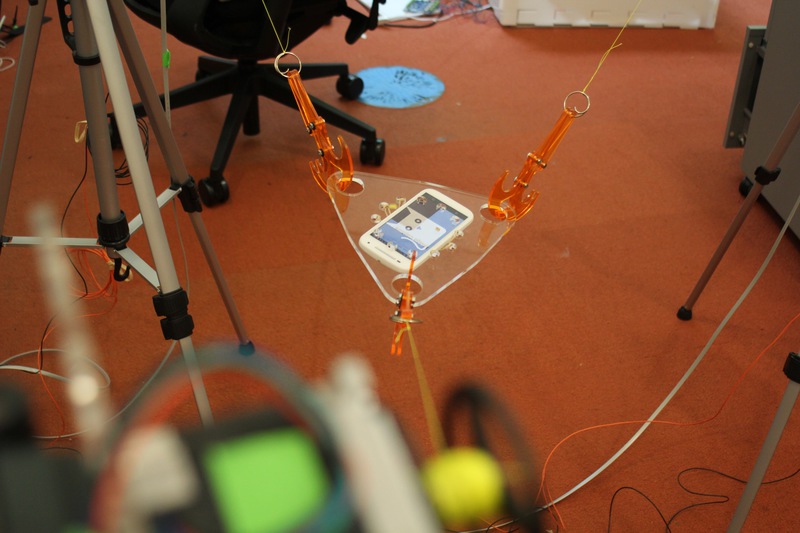
The plate will be kept as simple as possible, with the intention of holding a smartphone at its bottom, and one acoloca on its top, and with three holes to allow connection to the axis cables.
To attach the phone, I'll be using elastic bands. I'll attach the elastic bands using small holes with bump features. The modeling is again on OnShape and is basically mostly using the circular pattern action to repeat holes and structure around the center.


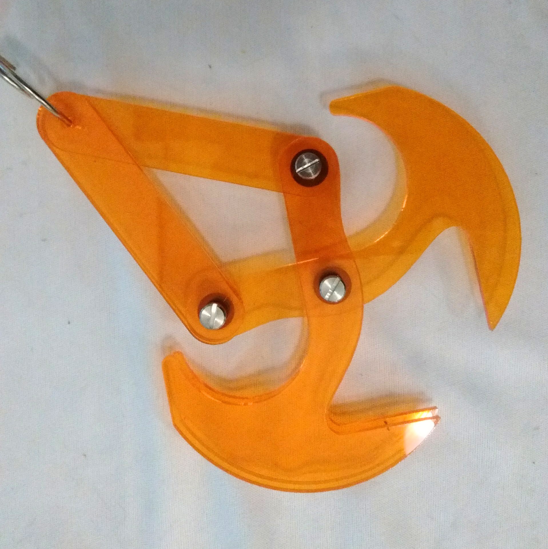
As for the hook, because my sizes changed, the previous one is too small. I could have just scaled up, but time is not available, so I'll be laser-cutting new hooks (the previous ones were 3d-printed).
I borrowed the design from the gravity hook made of two front blades and two back bars that work together as a hook.

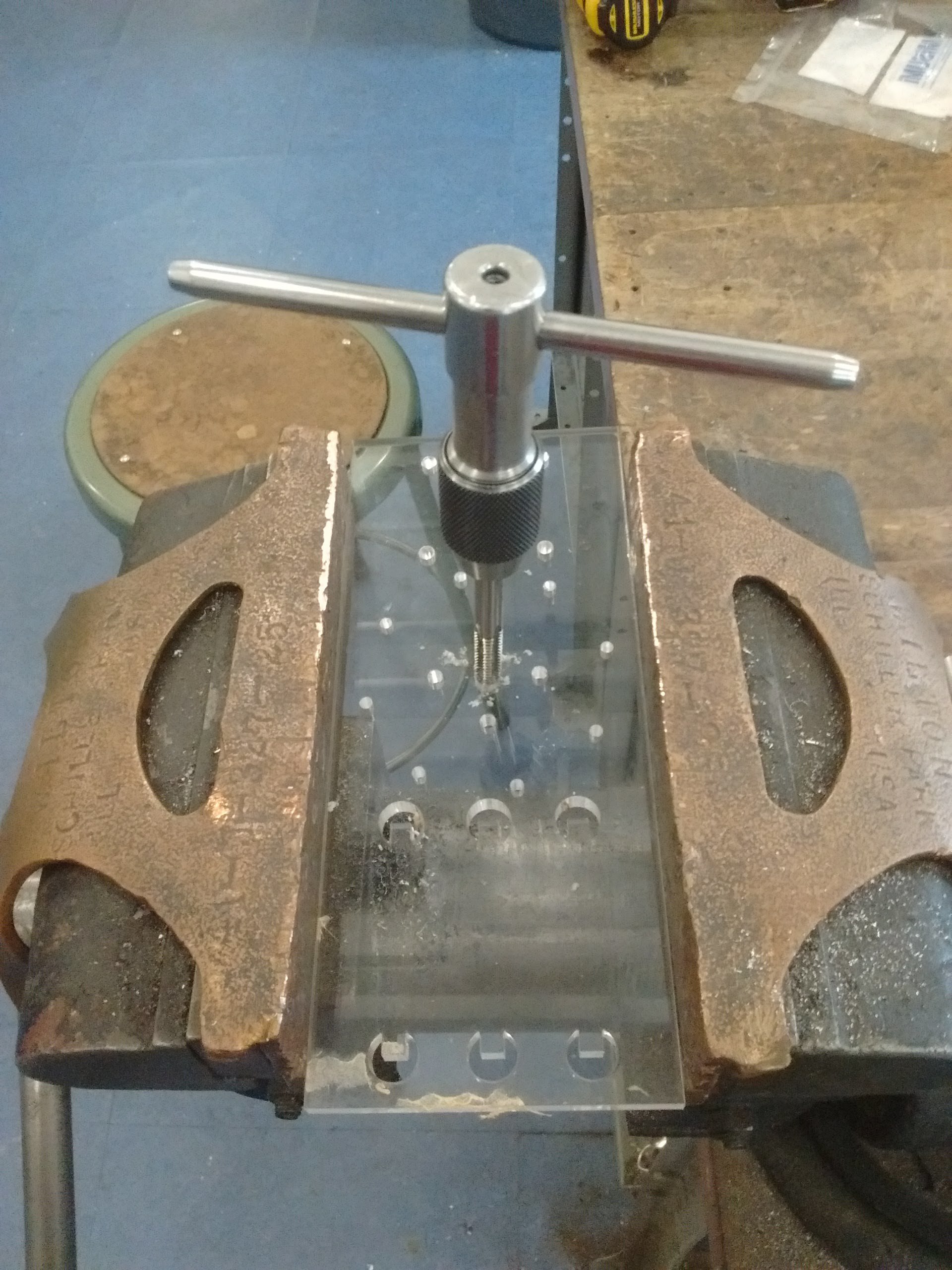
For the purpose of easily installing the winch anywhere, I'll be using tripods. This means connecting the whinch to the tripod either through its standard 1/4'' d-ring screw, or creating the mount directly. I went with the screw: this just means tapping a 1/4 inch screw hole.
Regarding the design, it took me a while and I created way too complicated cages for the stepper motor initially. Some of them are visible on the design document.
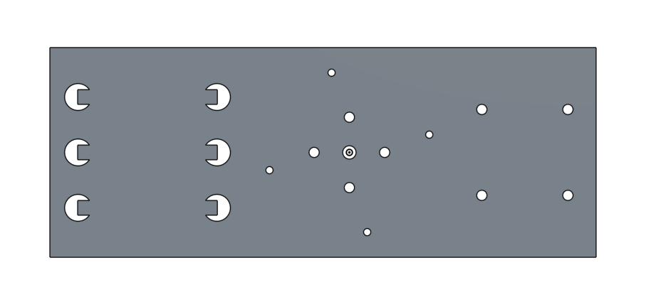
I finally went with a simpler single connector plate with various types of holes. The center hole for the 1/4 inch screw requires to be tapped and so I learned that we still need to cut with a corresponding diameter, which I got using drilling tables for tapping. In my case, it's a coarse 1/4-20 thread, so the drill diameter is 0.2010 inch.
We connect the stepper motor and its board, and we test and it's working!
To really do calibration, I will need multiple instances of my little acoloca package. I went and created the remaining ones. I have components for 4 instances, so 4 it is.
One of the instances broke the top panel, probably because of some internal friction. It would be worth doing a further iteration to improve what can be considered a mess of cables. What matters now though is to check that things are working and implement the software that drives all of that.

And here is a fast-paced overview of the 9min for one instance:
I tried to get my PLL to work properly and got initial promising results.
But then I attempted to measure the deviation and it was terrible.
It seems completely inaccurate.
I decided after hours of debugging to switch to pulse capture since this is the simplest,
and it took me several attempts, until I eventually realized that one inherent problem I was dealing with was the fact
that the function micros() gives very poor timing information!
Time values get coalesced into around 52 groups of same value.
I fixed this by using the timers in conjunction with PPI (thus avoiding the use of any CPU time). The code is the following:
void sync_setup(){
  // setup precise timing
  // timer3 accumulate microseconds
  // timer2 pushes microseconds from timer3 to its cc register
  NRF_TIMER2->PRESCALER = 0;   // 16 MHz base frequency
  NRF_TIMER2->MODE = 0;        // Timer
  NRF_TIMER2->BITMODE = 0;     // 16 Bit timer
  NRF_TIMER2->CC[0] = 16;      // roll back every microsecond
  NRF_TIMER2->SHORTS = 1;      // CC0 clears counter
  NRF_TIMER2->TASKS_CLEAR = 1; // clear timer for now

  NRF_TIMER3->PRESCALER = 4;   // 1 MHz base frequency
  NRF_TIMER3->MODE = 0;
  NRF_TIMER3->BITMODE = 3;     // 32 Bit timer
  NRF_TIMER3->TASKS_CLEAR = 1;

  // setup PPI
  NRF_PPI->CH[1].EEP = (uint32_t)&NRF_TIMER2->EVENTS_COMPARE[0];
  NRF_PPI->CH[1].TEP = (uint32_t)&NRF_TIMER3->TASKS_CAPTURE[0];
  NRF_PPI->CHENSET   = PPI_CHEN_CH1_Enabled << PPI_CHEN_CH1_Pos;

  // start us timer
  NRF_TIMER2->TASKS_START = 1;
  NRF_TIMER3->TASKS_START = 1;
}

typedef unsigned long timestamp_t;
timestamp_t sync_micros() {
  return NRF_TIMER3->CC[0];
}
And then we test it over a meter. The results are very promising, although I assume this only works really well in a quiet environment. The jump at 40mm and 90mm is what I would really expect in reality, so +/- 5cm. This is just a prelimiary test, and also a very naive pulse detection implementation: finding the max peak over time period of meaningful range. For each distance, I gathered 5 sample timings. See the data points there.
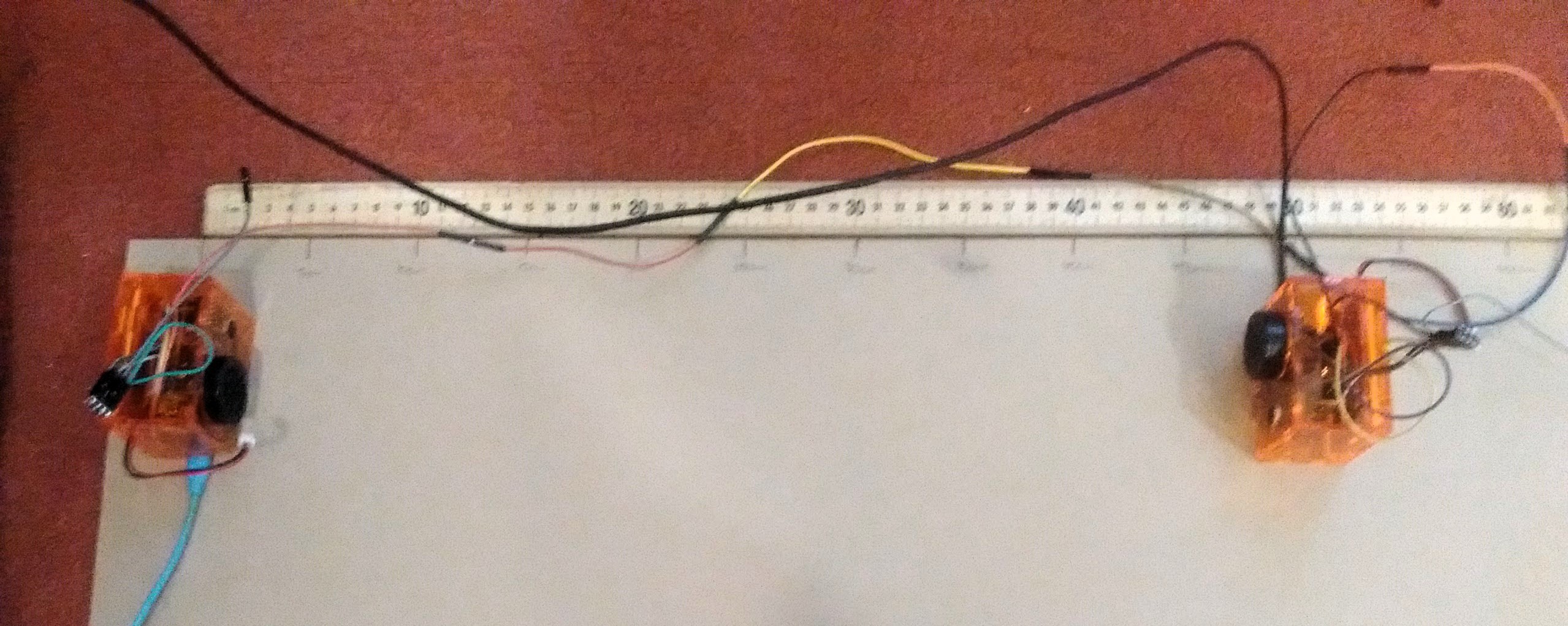

Here is a short example video with three pulses.
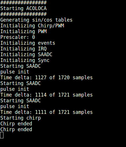
Given the reading in the console, this corresponds to slightly below 30cm (~28cm or ~11inches) and the mapping confirms it.
I saw that the orientation can have an impact on the mapping. By rotating one module by 90 degrees, the distance measurement shifts by around 2 centimeters. Lots of potential extra characterizations could be made.
For the routing, I used the base of mkterminal.js from Jake and added a few functions
to set a default speed, acceleration, acceleration and deceleration length, direction, and undoing packets.
It works almost fine. Sometimes, only one axis gets triggered and the others don't respond.
Not quite sure where that comes from.
The routing code is there as well as on the repository in tools.
I also attached my phone with elastic bands (thanks to the hooks that I laser cut), and started my webapp to enable taking pictures via wifi. This is not integrated yet with the routing, but could easily be. The routing code is in the repository under web.