
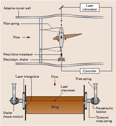
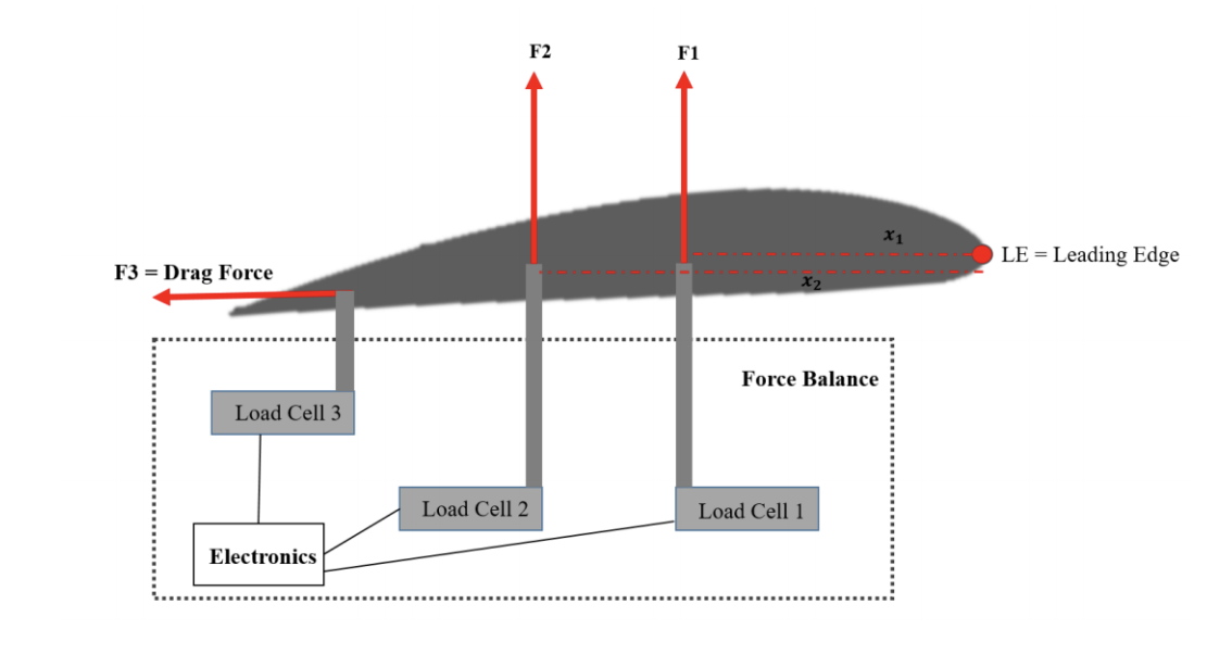
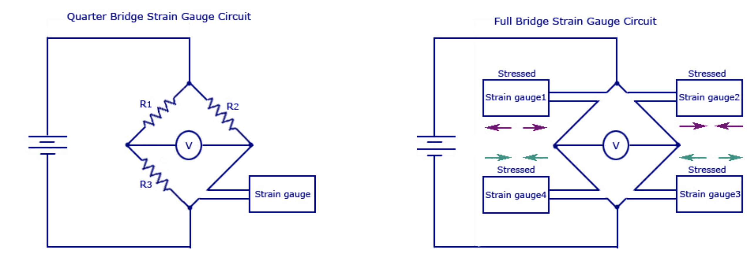
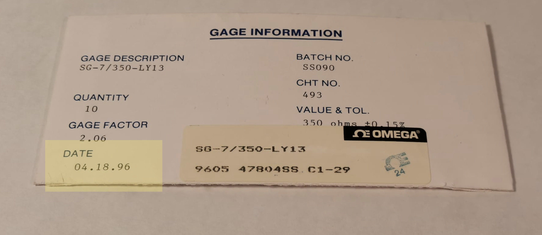
This week I decided to dive in first in have a feeling about if Im able to build my own sensing platforms with arbitrary shape. To do so I am going to build some classic loadcells. Firstly I am going to make a quarter bridge with a simple monolithc bar just to warm up and to see if I can read voltage. Strain gauges are variable resistors but we need to convert that Ohms meassurements into voltage as it is way more handy to be readded by a microcontroller. The circuit that enables you to do so are Wheatstone bridges.
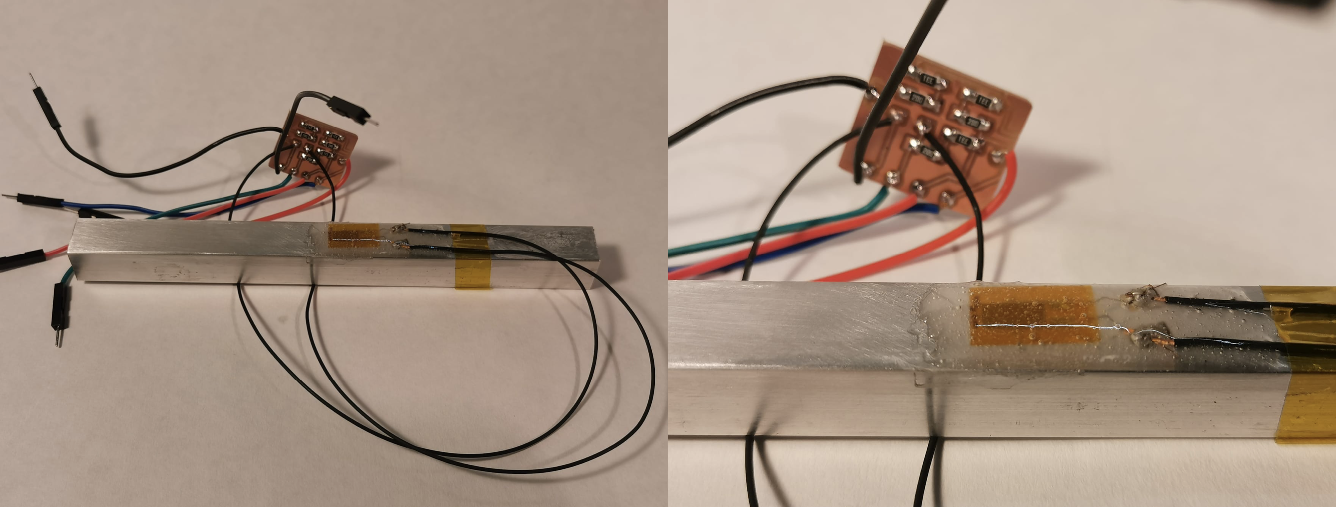

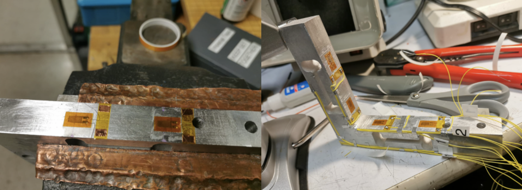
 You can check the video here.
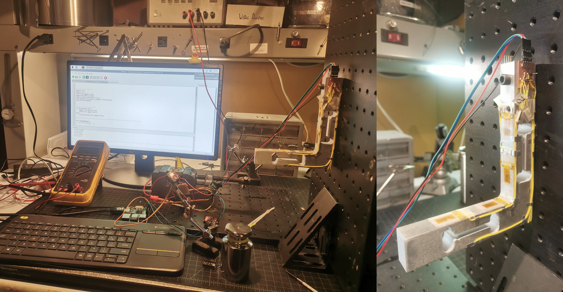
This week Ive been working in the code above, reading the load cell and plotting real data. Also Ive been doing microstepping raspi code with a NEMA17. Im ready now to controll the angle of attack, read the load and act according.
My ultimate goal is make the wind tunnel talks with the morphing wing.
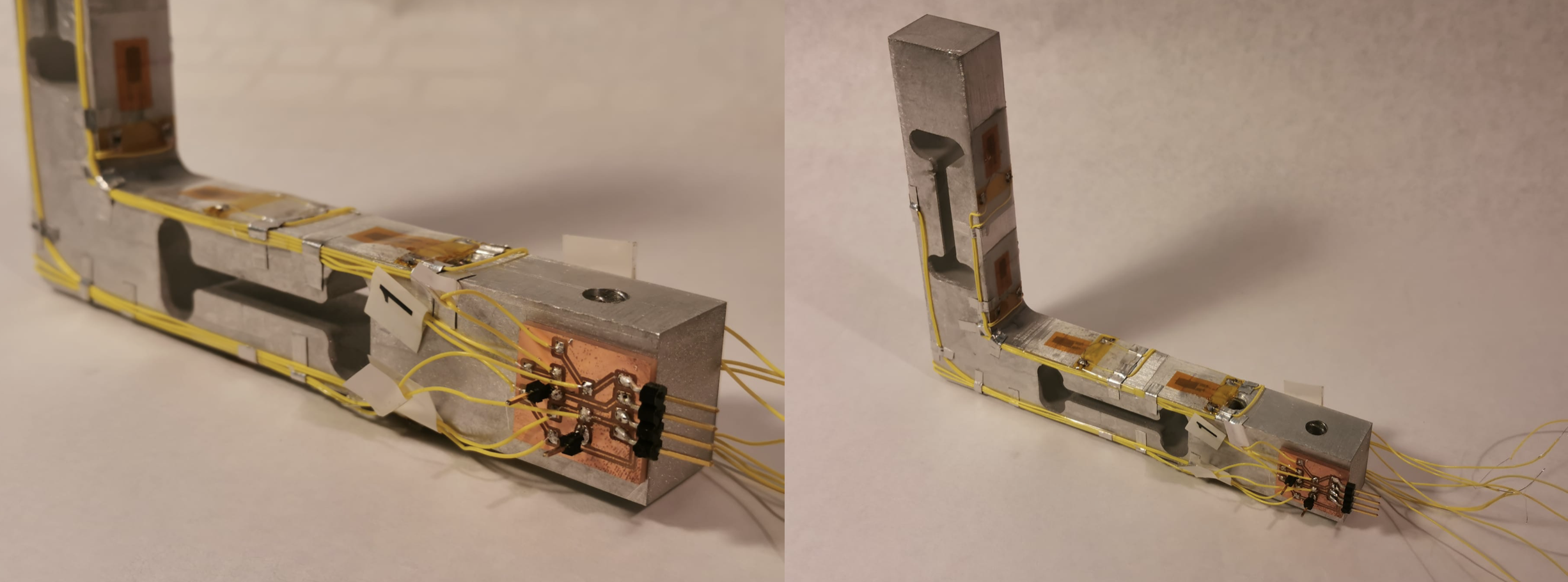
This last weeks Ive fix the final design for the horizontal balance, manufacture subcomponents, assembled them, failed a bunch of times, set up the teensy to serial read the HX711 at 80Hz and somehow make all work together.

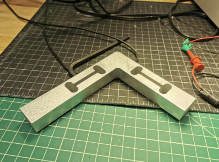
EDM LOADCELL
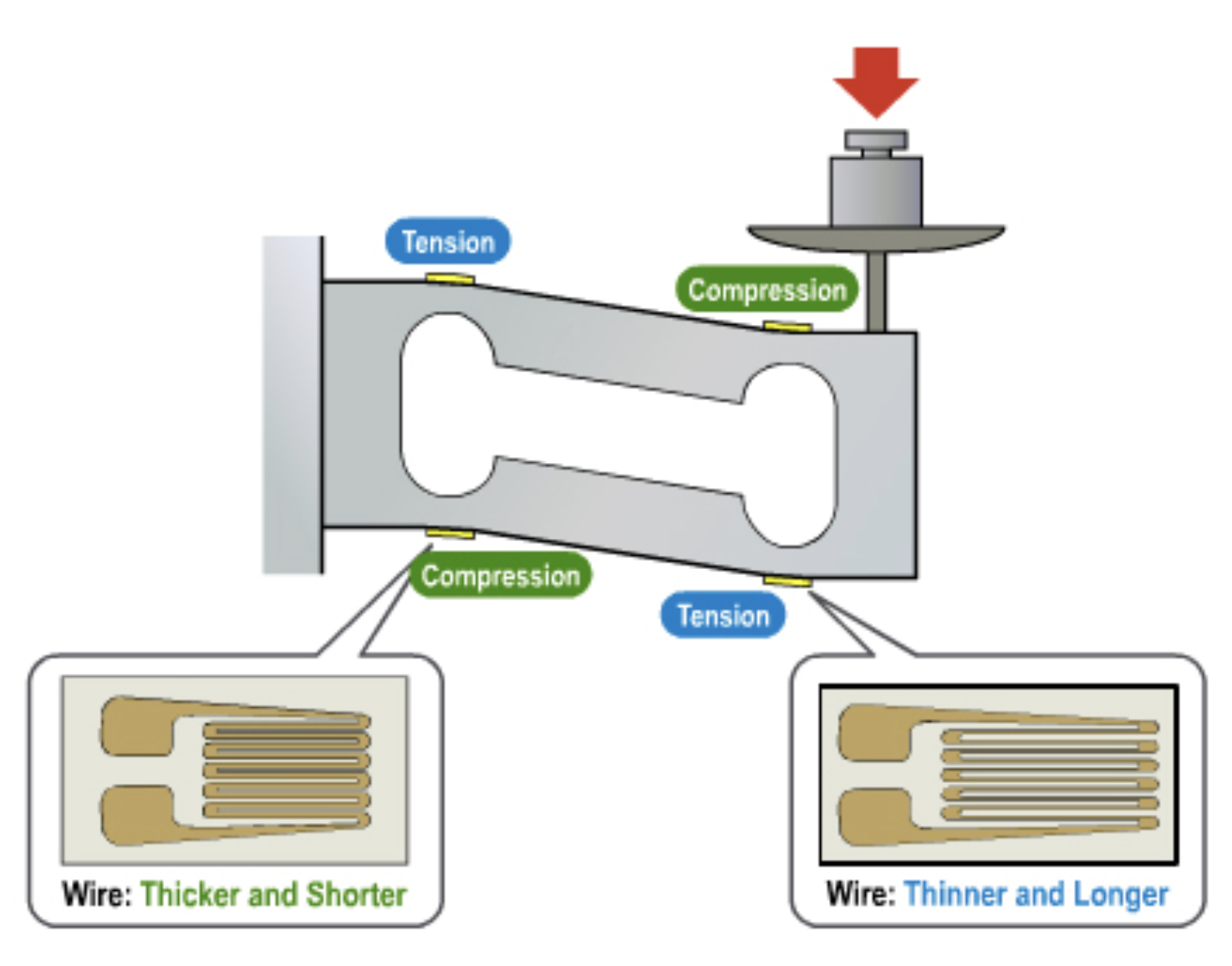
I firstly decided to jump from waterjet to EDM the load cell. I decided so to controll way better the tolerance of the thin section that the L structure have. Of course Zach helped me with the EDM process.
Later, I realized that maybe its not needed as you'll need to sand the lateral face to make the superglue work.

Ive also did cut the main base using the waterjet and tapped all the holes to be M5.
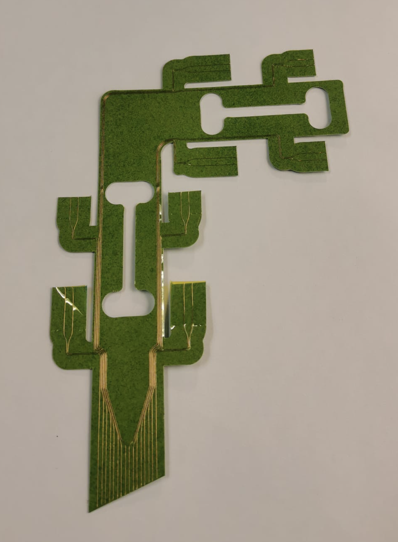
WIREPLOTTING WITH THE ZUND
Sam Calisch , PhD student from our lab developed a beautifull hack for the zund as is wireplotting. You can check here the process (last chapter). That allows you to print a continuum (hamiltonian) path over a sticky material that, in my case, I used later to paste it on the loadcell and route all the neede cables.
As in the last loadcell it was a nightmare to route one by one those tiny cables I decided to automate it and even use thinner cable (41 AWG). First I did a dxf of a closed circuit that later will be cutted the perimeter in a way that breaks the continuity of the path, with the Zund in the same job

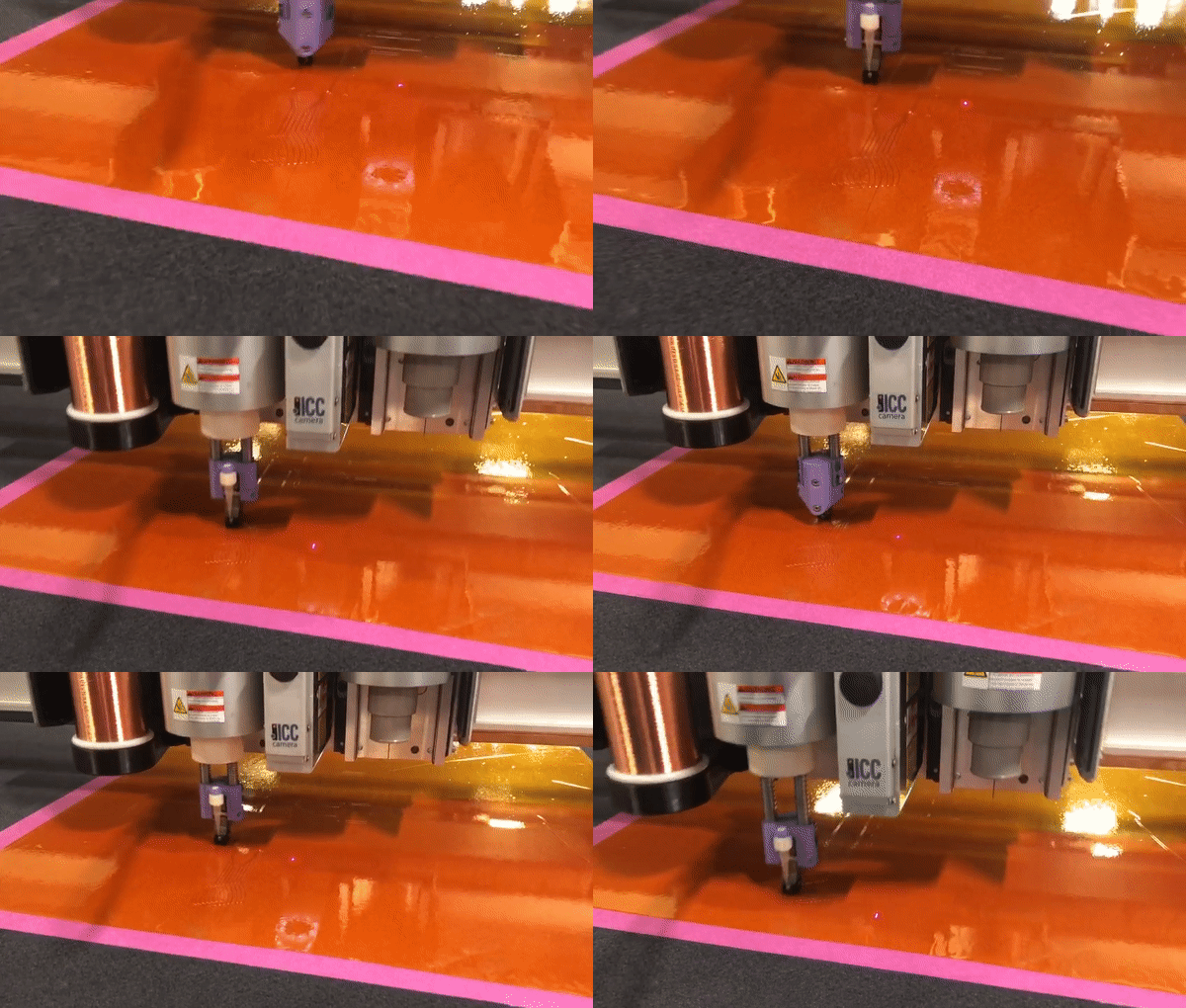 And heck here the result
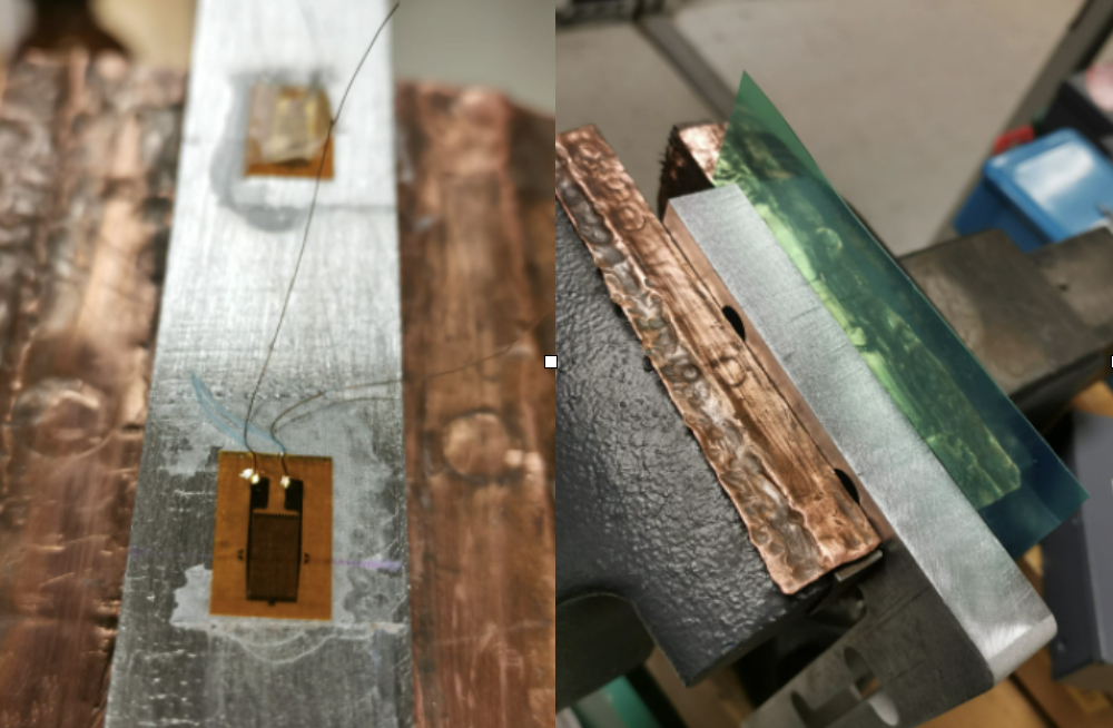
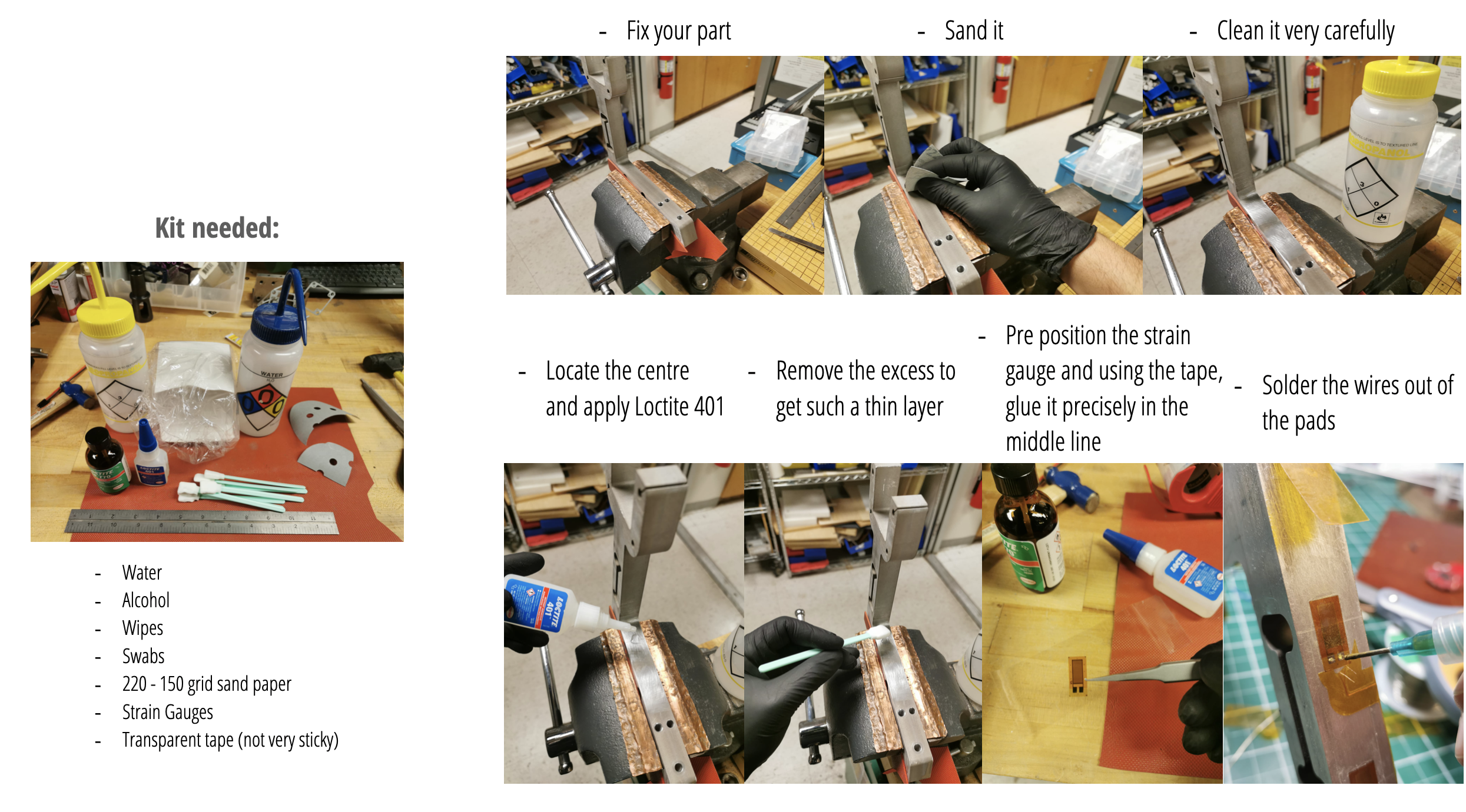
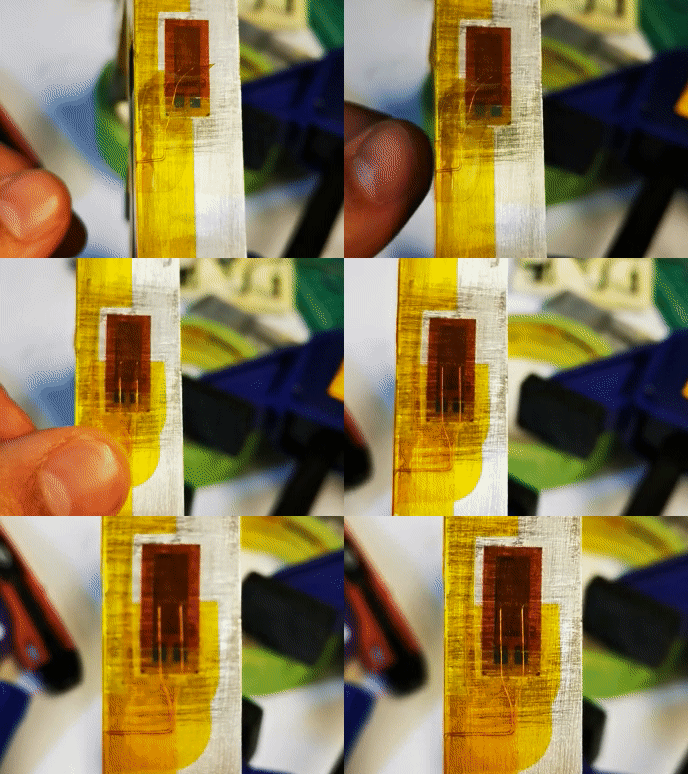
INSTALLING STRAIN GAUGES
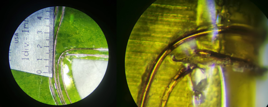
There's a reason why the protective kapton layer is more than needed.
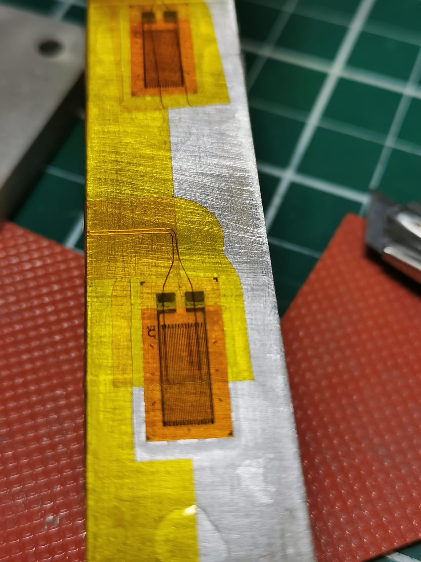
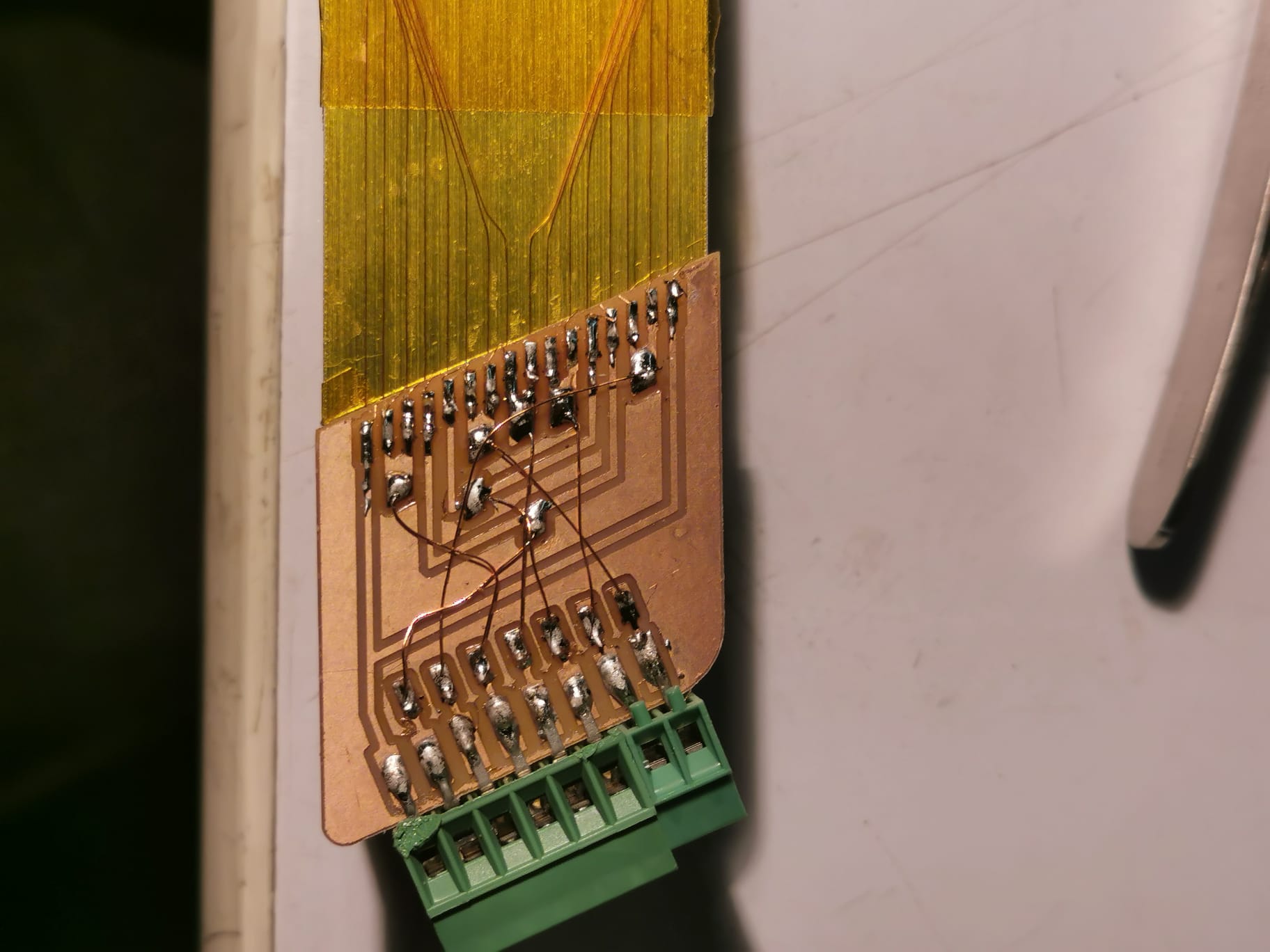
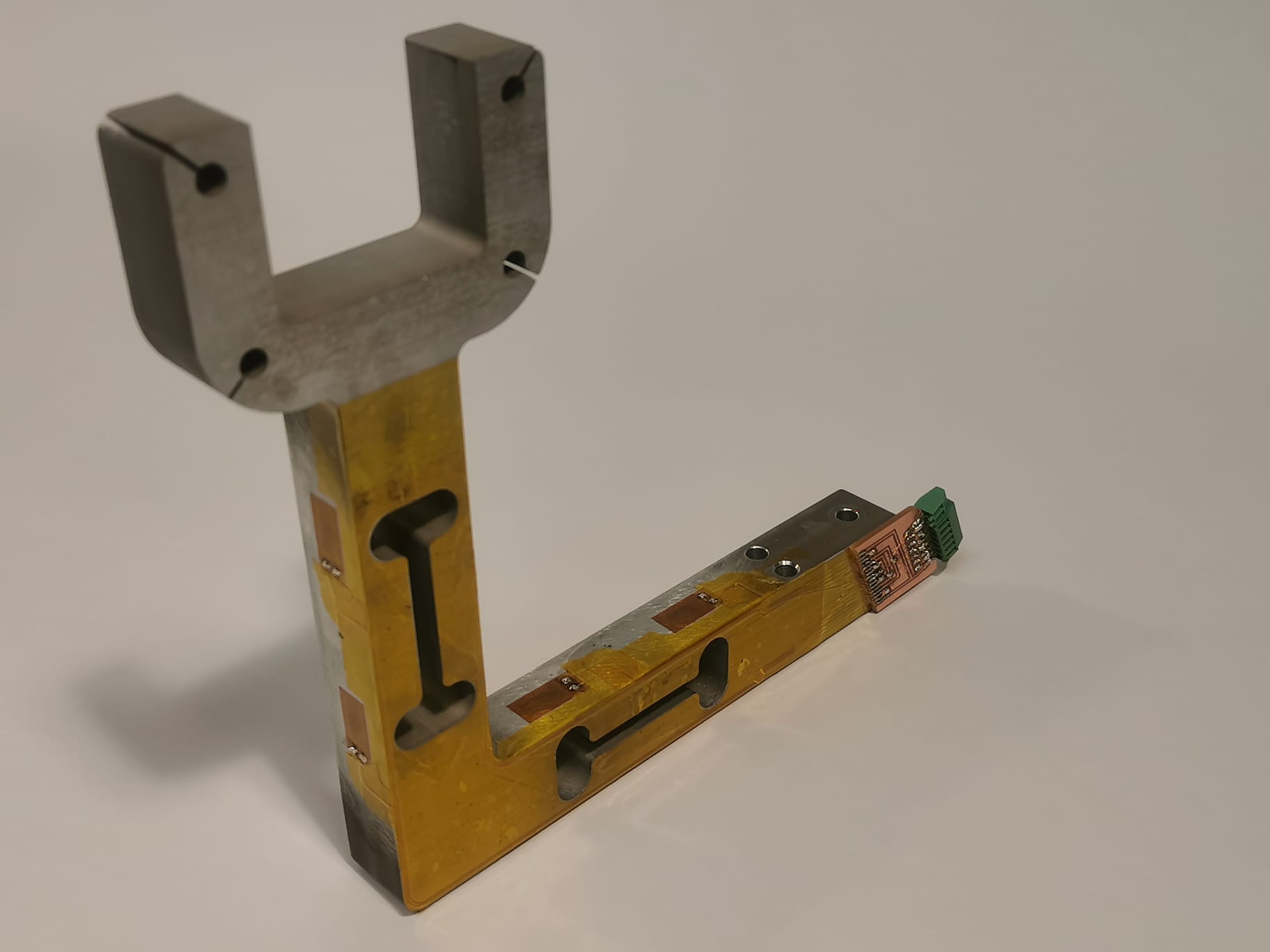
After reading for a while now the horizontal platform Ive been manufacturing and also, after adding the pitot tube, I noticed the need of implementing signal processing of the readed values.
The system architecture I decided to follow inside this project is:
I started to research which filters could I use and Ive been implementing a Kalman filter, using a library, and it worked. After commenting it with Dave and Chris, they told me that my use was the perfect situation to implement a Low Pass Filter. This one yes, I implemented it by code. Here you can check how it smooth the signal of the pitot tube.
It was a meeeesss the way I had hooked up all the sensors using multiple breadboards, impossible to trace back any issue and I was procrastinating the decision of making a PCB to clean that.
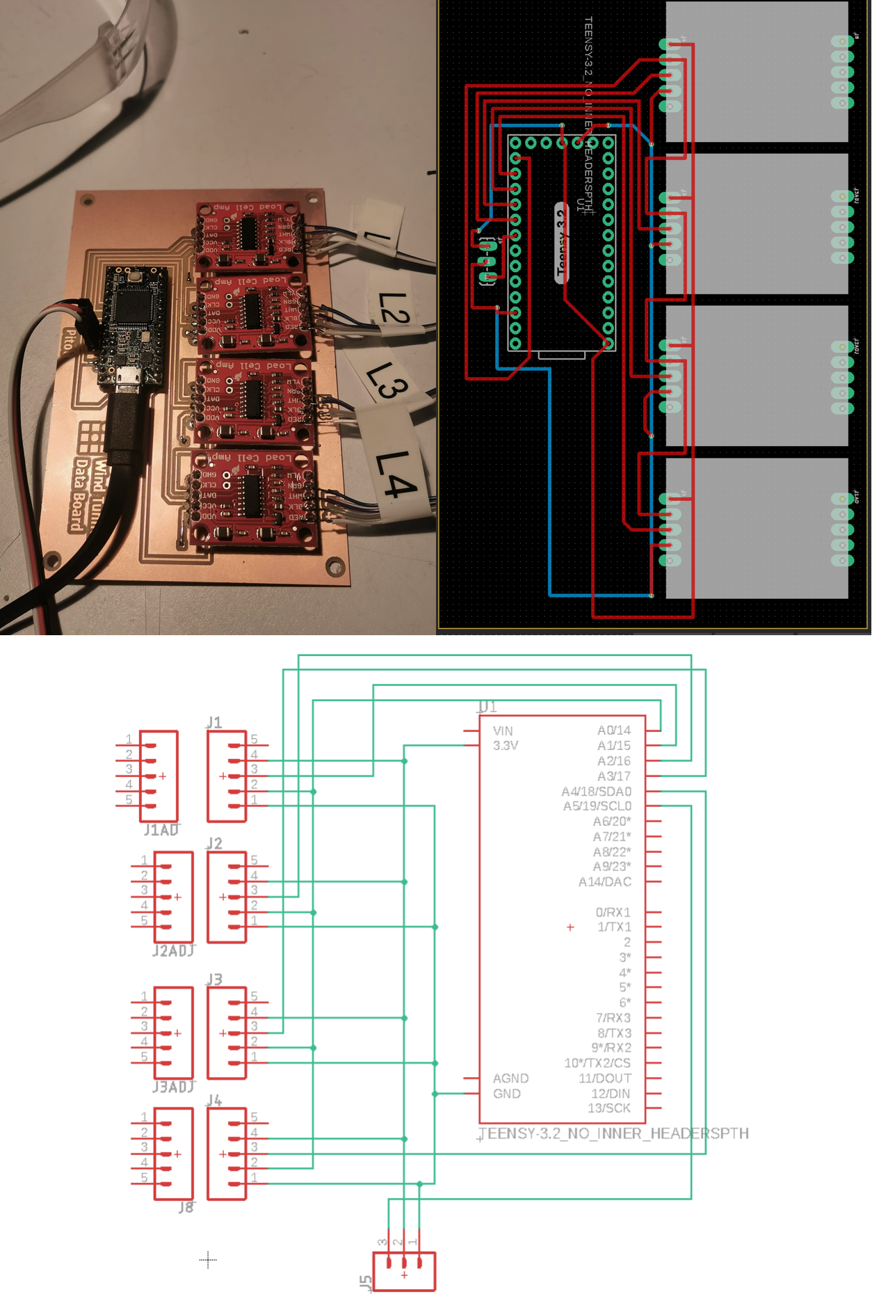
I took this class excited to learn more about system architecture, learn more to play around boards sensors, integrations and doing custom sensored platforms, and so far, Im sure ive learnt a bunch.
For the final presentation I want to show a couple of wings and , ideally, a morphing one showing different L/D values (that will require to read and store data on a sd card, its gonna be a bbbunch of work.)
Maybe, the question I am asking is, Can I make a wind tunnel able to be replicated in a Fab Lab? . The intention has been to do everything by myself, not buying elements (only if neccesary) and so far I think I am putting in the table a strong and precise instrument that I will have fun with.