ZCDL is a data link layer that is optimized for extreme memory efficiency. It requires only two bytes of dedicated send/receive buffers (for a simplex connection), and can operate without any copy operations between buffers or between ZCDL-managed and application-managed memory. ZCDL requires two wires for a simplex connection, or four wires for a full duplex connection.
For simple applications, ZCDL can be used on its own, with no additional layers between it the application. Network topologies could be supported by inserting networking and transport layers on top of ZCDL (see the ZCLN).
ZCDL is a descendant of the DICE token passing model. In this class I separated the data link logic from the token logic, implemented it in Verilog for FPGAs, and measured performance. The code lives in the zcdl branch of the DICE firmware repo. Changes will be merged with the main DICE branch soon.
A basic simplex connection requires two wires: the signal wire and the data wire. Existing implementations use direct connections with 3V signals.
The signal wire allows the receiver to expose one bit of state to the sender. Broadly speaking, it is used to communicate to the sender when the receiver is prepared to receive data. Since the sender only reads this wire, it is safe for the receiver to actively drive it high and low. (A possible extension discussed below would instead require that the signal wire have a pull-up resistor connected on the sender side, in which case the receiver would allow the line to be pulled up rather than driving it actively.)
The data wire is used for serial communication. However ZCDL is agnostic as to how the data communication actually occurs, so you could replace this with RS-485 transceivers and a twisted pair for longer cable distances, or with quad-SPI if you want more speed.
Duplex connections are formed out of two independent simplex links. Being a data link layer, ZCDL supports a connection between two nodes. But many nodes may be linked together in chains, grids, etc. as long as there is some layer on top of ZCDL that can do the required routing.
There is one frame type. It consists of a single byte header, followed by a varying number of data bytes. The header byte encodes the frame format ID (FFID). The FFID can be used to look up the number of data bytes in the frame, as well as how to interpret them.
| B0 | B1:n |
|---|---|
| FFID | Data |
Frames with an FFID of zero always have the same size and interpretation, and are handled by ZCDL itself. These are known as handshake frames. Frames with other FFIDs have application defined sizes, and are interpreted by the application (or intermediate networking layers) as opposed to ZCDL. The application defined FFIDs and their accompanying sizes must be determined before any communication begins. In practice, on MCUs, this usually means they are determined at compile time and baked into the firmware. (Though the ZCDL firmware stack itself wouldn’t mind if you worked out the FFIDs and sizes at runtime, as long as they don’t change once communication is underway.)
The point is that applications (or other networking layers) can define a variety of appropriate frame sizes. Since they’re application defined, their sizes can be matched to the relevant use cases. And since ZCDL knows the frame sizes in advance, it can place incoming data in a buffer of the correct size, which can be handed directly to the application without being copied. A DICE DEM application, for instance, can have different frame types corresponding to particle data and force data. These can have different corresponding ZCDL frame sizes so that exactly the right amount of data is sent, and exactly the right size of buffer is used for each transfer. On the other hand, a networking layer built on top of ZCDL could have frame types for sending data, acknowledging receipt of data, and requesting a resend. Ultimately this should make application code simpler to write and more efficient, since instead of repacking data from rx buffers into a final struct, you can just receive the data in exactly the format you want in one shot.
Handshake frames have exactly one data byte. Application defined frames must have at least one data byte.
Every application defined frame (FFID other than zero) is preceded by a handshake frame (FFID of zero). The data byte in a handshake frame indicates the FFID of the following application defined frame.
The receiver uses the signal wire to indicate which type of frame it is prepared to receive. When the signal wire is low, it must be prepared to receive a handshake frame. When the signal wire is high, it must be prepared to receive the application defined frame that was indicated by the preceding handshake frame.
Note that this protocol relies on one bit of state: the sender and the receiver must stay in sync as to when to send a handshake vs application defined frame. If they get out of sync, the sender can end up waiting for a signal that will never arrive (i.e. it wants to send a handshake frame, but the receiver is waiting for an application defined frame, or vice versa). To ensure that nodes are synced, upon power up all receivers should prepare to receive a handshake frame. All senders should wait long enough before sending data that the receivers have enough time to power on and drive their signal wires low.
This could be made more robust by adding pull-up resistors to the signal wires on the sending side, so that a broken connection reliably manifests as the inability to send the first handshake frame. This would increase baseline power consumption to some degree. I have not explored this yet, but plan to in the future.
To avoid having the ZCDL implementation use up memory with dedicated buffers, buffers are shared between the ZCDL firmware and the application code. To make this work, API methods are provided to attach/detach buffers to/from the ZCDL instance. Buffers are tagged with their FFIDs. While attached to the ZCDL instance, they can be used to receive data. To send data, the application can detach a buffer from the ZCDL instance (or use another it has available), fill it, and pass it to the ZCDL instance to use for sending.
As such there are five methods that applications can use to interact with the ZCDL instance.
// Hands a buffer to the ZCDL instance, so that it can be used for receiving frames. Usually all
// buffers are handed to the ZCDL instance at the beginning of program execution.
void attach_buffer(TokenBuffer buffer, uint32_t ffid);

// Returns a buffer for the application to use, generally so it can prepare a frame for sending.
TokenBuffer detach_buffer(uint32_t ffid);

// Initiates a data transfer. The actual transfer happens asynchronously (driven by interrupts).
void send_frame(TokenBuffer buffer, uint32_t ffid);

// The application uses this method to check if a particular type of frame has been received.
bool query_frame(uint32_t ffid);

// The application uses this method to consume a frame. If the frame has not yet been received, this
// method blocks until it is. Once the application has used the data it must return the buffer to
// the ZCDL instance (via attach_buffer).
TokenBuffer receive_frame(uint32_t ffid);
Currently on the FPGA I cheat a bit by allocating one big buffer that can fit any application defined frame. This makes sense because I’m only using the FPGA to forward data, as opposed to processing it, so even with this hack I’m still achieving zero copies. If we want to process data on the FPGA directly, and different frame formats would be processed in different ways, we would simply need to (de)multiplex to the different frame buffers.
module zcdl_receiver #(
    // These connect the receiver to a sender.
    input zcdl_rx, 	     // we receive serial data on this wire
    output reg zcdl_sig, // when low, we're ready to receive a header; high, a payload

    // These let you pull the data out of the receiver.
    output reg[7:0] ffid_out, // FFID byte
    output reg[7:0] byte_out, // data is pulled out one byte at a time
    output wire byte_out_valid, // when high, byte_out and ffid_out are displaying meaningful data
    input pop, // pull this high to indicate that you've read a byte and are ready for the next

    // Note: clock and reset signals are used, but not shown here.
);
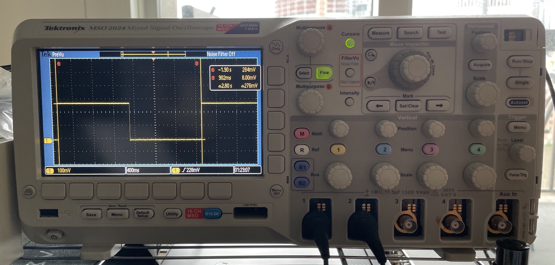
As expected the total bitrate (counting only data bytes) depends on the size of the payload. All timing data below was collected by toggling an output pin after sending some number of frames, and capturing the resulting signal on an oscilloscope. The sending node repeatedly sent frames as fast as the receiver would accept them. The receiving node immediately threw away each frame it received.
For sufficiently large frames, the protocol achieves the maximum theoretical data transfer rate (relative to the baud rate of the underlying serial connection). This demonstrates that the flow control works well: the sending node doesn’t send data before the receiver is ready (otherwise they would get out of sync); nor does it take any appreciable time for the receiver to communicate that it is ready for the next frame and for the sender to respond.
This table shows total bitrates for a variety of payload sizes. All data was collected with a base transfer rate of 3 MBaud.
| Payload Size (Bytes) | 4 | 16 | 64 | 256 |
|---|---|---|---|---|
| Data Rate (MBit/s) | 1.4 | 2.0 | 2.3 | 2.4 |
With small frame sizes, the overhead of the protocol is noticeable. By 256 bytes, however, we are achieving near the theoretical maximum. (For every 8 data bits, there is one start bit, and a gap of one bit, so we can’t expect to achieve more than 80% of the base baud rate.)
This table shows total bitrates for a variety of payload sizes. All data was collected with a base transfer rate of 1.5 MBaud. (For now I’m clocking the FPGA at 12MHz, and for receiving serial data I sample 8x during each bit period, so 1.5MBaud is the max rate.)
| Payload Size (Bytes) | 4 | 16 | 64 | 256 |
|---|---|---|---|---|
| Data Rate (MBit/s) | 0.7 | 1.0 | 1.1 | 1.2 |
Unsurprisingly the data is basically identical (relative to the baud rate), since the protocol is the same.