ZCLN is a simple, vaguely EtherCAT inspired networking system for line and loop (i.e. ring) topologies. It can run exclusively with MCUs, or for better performance, a combination of FPGAs and MCUs. It is built on top of the Zero Copy Data Link layer, and is similarly optimized for memory efficiency.
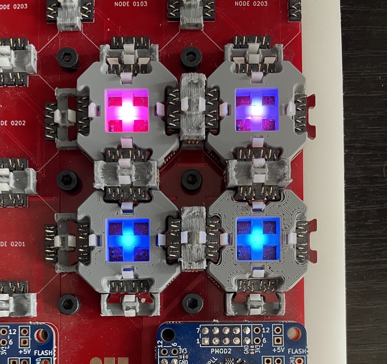
An initial MCU version has been implemented, and an FPGA version is in progress. The former has been tested on DICE hardware (but would be easy to port to other SAMD51 designs), while the latter will run on a new dev board that connects an FPGA to a SAMD51 with quad SPI. The code lives in the zcdl branch of the DICE firmware repo.
A ZCLN consists of several ZCDL connections arranged in a line or loop. Each node must have a unique ID, but these can be assigned dynamically (more on this later). There must be some node with an ID of zero. For most purposes, ZCLN does not distinguish between head and drop nodes. However in some cases the node with ID 0 is treated as a special case (see below).
A ZCLN packet consists of a three byte header, followed by a varying number of data bytes. The header bytes encode the IDs of the sender, the intended recipient of the data, and the number of hops the packet has taken so far. Each packet ends up packed inside a single ZCDL frame, and the ZCDL frame format ID (FFID) is passed through the networking layer to the application. For this reason it’s often convenient to think of the ZCDL frame/ZCLN packet as a single structure with four header bytes: the FFID, the sender ID, the destination ID, and the number of hops. (Note that the handshake frames from ZCDL don’t contain ZCLN packet data.)
| (B-1) | B0 | B1 | B2 | B3:n |
|---|---|---|---|---|
| (FFID) | Src ID | Dst ID | Hop Count | Data |
Several IDs are reserved and have special meanings. 255 is the broadcast ID. Packets with this destination address are forwarded until the end of the line (for line topologies), or until they reach their sender (for loop topologies). 254 is the neighbor ID. Packets with this destination address are always consumed by any node that receives them. This enables a bootstrapping process to occur before node IDs have been assigned.
When a node receives a packet, it either consumes it or forwards it to the next node in the line (or loop). When a packet is consumed, nothing else is passed on to the next node. When a packet is forwarded, since the destination ID is near the beginning of the packet, it is possible to start forwarding the data before it has been completely received. This is not implemented so far in MCUs, but will be a natural fit for FPGAs.
If the application tries to send a packet and a different packet is already being forwarded, the new packet is queued. For now packets are sent on a first come, first served basis. If contention becomes an issue it may be advantageous to develop a more robust prioritization scheme.
Though the networking layer itself doesn’t default to sending “trains” of data continuously around the loop, this is a natural fit for an application level communication framework built with ZCLN. In this manner the network can behave similarly to an EtherCAT loop.
When the network topology is a line, packets that reach the end without finding their destinations are dropped. Generally this should be considered an error. In a loop, if the application sends a packet with an invalid ID, it may continue to cycle forever. So far such packets have not become an issue, but if needed a form of garbage collection could be implemented where packets are dropped if their hop count exceeds some limit (such as the total number of nodes).
Bootstrapping the node IDs is almost always the first thing a ZCLN application does, so it is effectively part of the networking protocol. The typical pattern is to reserve an FFID of 1 for dynamic address assignment. It only requires one byte of data. One predetermined head node initiates the process, by sending a packet with a destination ID of 254, and a data payload of 0. Each other node consumes this packet and sends another with the data payload incremented.
Buffers are managed as in ZCDL. There are five methods that applications can use to interact with the ZCNL instance.
// Hands a buffer to the ZCLN instance, so that it can be used for receiving packets. Usually all
// buffers are handed to the ZCLN instance at the beginning of program execution.
void attach_buffer(ZCLNBuffer buffer, uint32_t ffid);
// Returns a buffer for the application to use, generally so it can prepare a packet for sending.
ZCLNBuffer detach_buffer(uint32_t ffid);

// Initiates a data transfer.
void send_packet(ZCLNBuffer buffer, uint32_t ffid, uint32_t dst);
// Helper method that should be called periodically to keep packets moving along the ring.
// This should eventually be driven from an interrupt, or packet receive events.
void forward_packet(ZCLNBuffer buffer, uint32_t ffid);
// The application uses this method to consume a packet. If the packet has not yet been received,
// this method blocks until it is. Once the application has used the data it must return the buffer
// to the ZCNL instance (via attach_buffer).
ZCLNBuffer receive_packet(uint32_t ffid);
This implementation is purely to test the functionality, and is somewhat specialized for DICE hardware. I will implement the protocol more generally for FPGAs (where it should be much faster anyway).
I have fragments of an FPGA implementation, but finishing it is difficult since I don’t yet have the right hardware to run it on. However this will soon change.
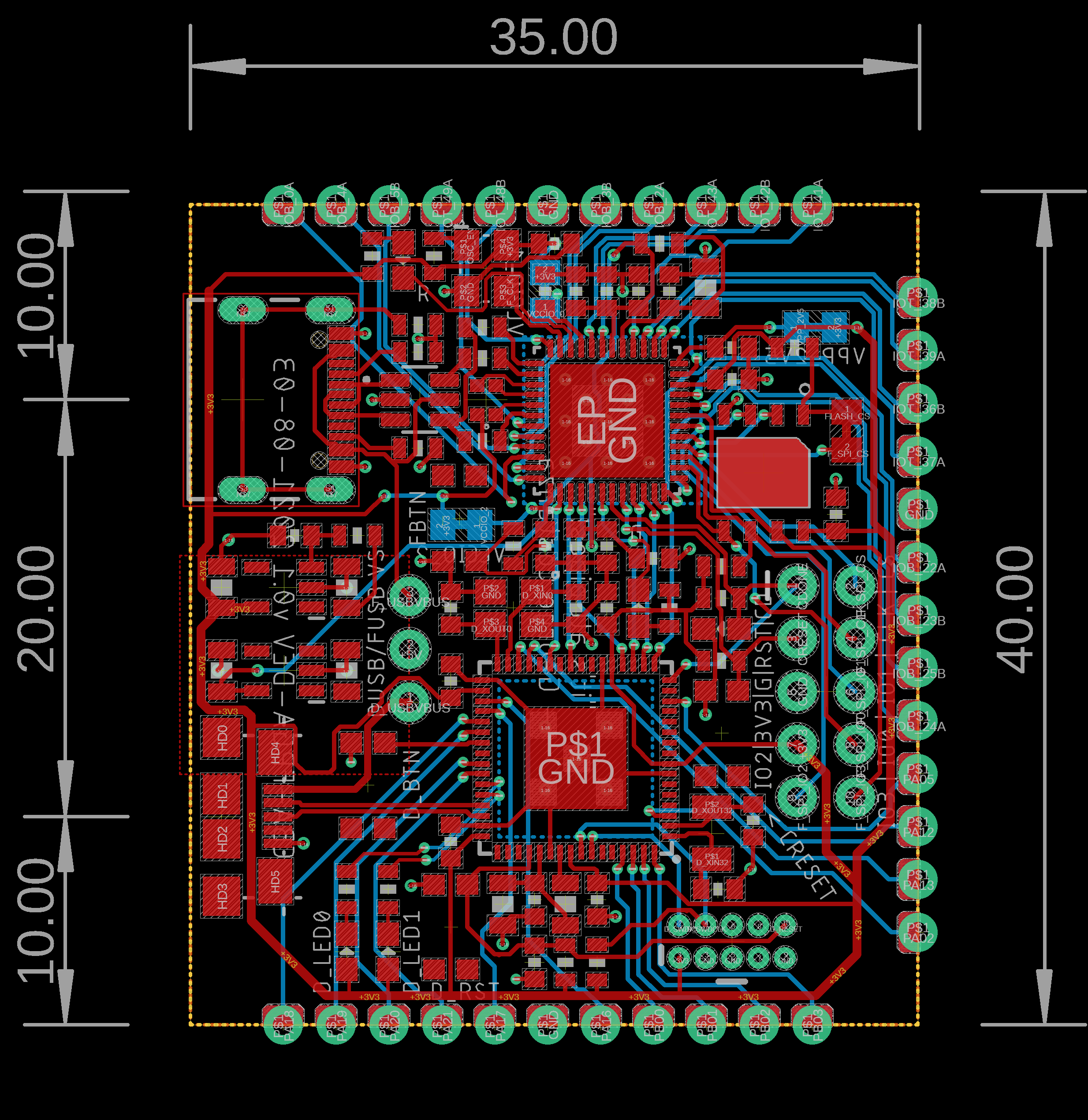
Over the summer, Jake, Zach, and I specced out a combination FPGA and MCU dev board. It connects an Lattice iCE40 FPGA to a SAMD51 via quad SPI (as on the iCEBreaker). It also breaks out several pins from each chip. Using these we will be able to attach various transceivers to test different physical layers.
The immediate implementation plan for ZCNL is to send COBS delineated data chunks between FPGAs. (My FPGA COBS implementation is here.) This moves away from ZCDL somewhat, but makes sense since the FPGA won’t be doing anything with the data except routing it to the next FPGA or its connected MCU, and thus can have one big buffer. The FPGA can start decoding packets on the fly, and check the destination address. If the packet should be forwarded, it will be able to start doing to immediately, without further COBS decoding, and before it has finished receiving the data. This will give a huge performance boost of the MCU version, which receives the entire packet before forwarding it. Meanwhile the FPGA will pass the data to its connected MCU using a ZCDL connection, so that the MCU can receive the data in the most convenient format (and not allocate extra buffers nor waste time with copy operations).
For longer runs, the idea is to use RS-485 transceivers and Manchester encoding. I implemented Manchester encoding on the FPGA here.
All timing data below was collected by toggling an output pin after sending some number of packets around a loop with the specified number of nodes, and capturing the resulting signal on an oscilloscope. A preselected starting node would send a packet addressed to itself, and wait for it to return after traveling around the loop. All other nodes immediately forwarded all packets (no packets were addressed to them).
For sufficiently large packet sizes, we approach the bitrate of the underlying ZCDL connection divided by the number of nodes. This is expected since each intermediate node fully receives the packet before forwarding it.
For smaller packet sizes, the overhead of the protocol is higher than bare ZCDL. This is also expected since we have three more header bytes to send with each packet (source, destination, and hop count).
| Payload Size (Bytes) | 4 | 16 | 64 | 256 |
|---|---|---|---|---|
| Data Rate (KBit/s) | 448 | 845 | 1.09 | 1.16 |
| Payload Size (Bytes) | 4 | 16 | 64 | 256 |
|---|---|---|---|---|
| Data Rate (KBit/s) | 226 | 424 | 542 | 585 |