Cable Driven Bending-Active Machine
AKA Really Big Z AKA SlopBot
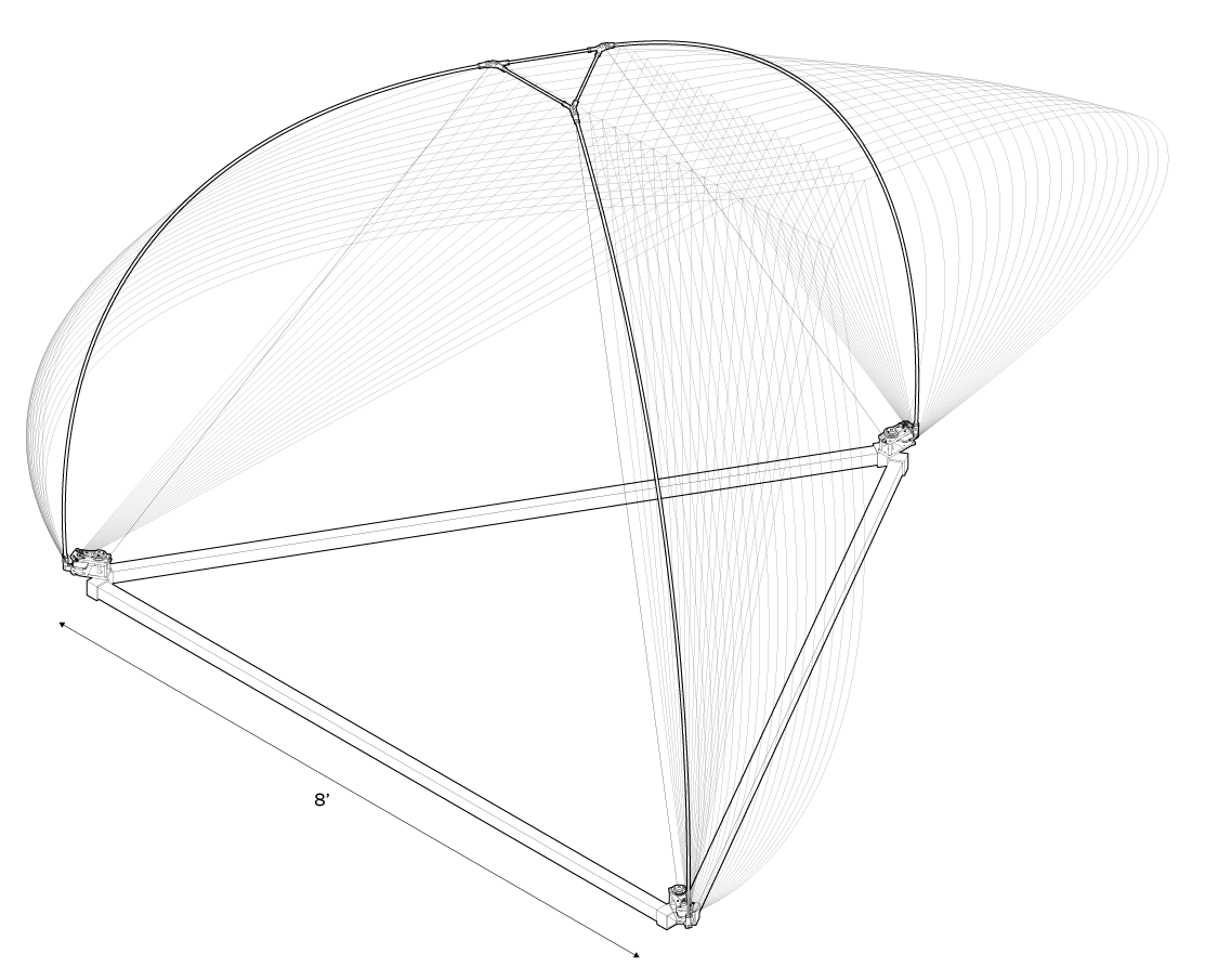
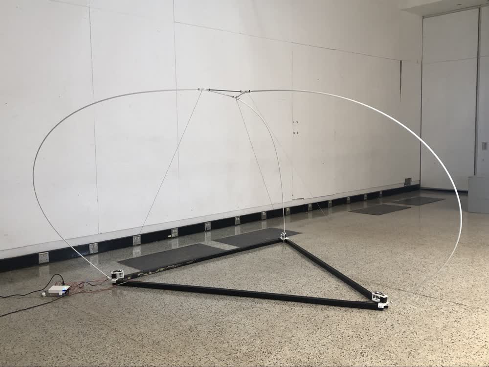
This machine aspires to have a really big build area while also being light and easily transportable for onsite use, somewhere remote. One way to achieve this would be with a cable driven machine suspended from trees, poles, higher elevations, etc. The problem therein is the reliance on three reliable anchor points, which may not exists. Here I present an alternative form of cable driven machine that is self contained and can simply be anchored to the ground. The machine couples the three driving cables with GFRP rods. As the cables are shortened, the rods bow and the restoring force in the rods pulls the cables taut. Currently, the rods I'm using, which are 3/8" GFRP, are too flexible so the machine is not really rigid enough to do anything useful. Use TBD.
In the video below I demonstrate the maximum reach of the machine. Another issue that is made apparent in this video is that depending on what kind of work the machine is doing, the cables might start to get in the way. This and other issues relevant to this project have been explored by Torbjørn Ludvigsen in the Hangprinter project. The line collision issue specifically is explored HERE.
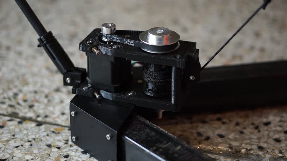
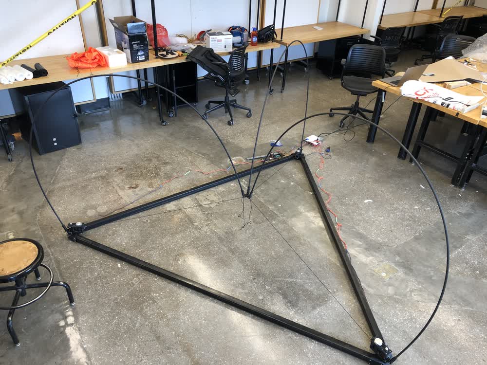
There is also the issue that as the cable is wound, the diameter of the winding spool effectively changes and therefore the travel per rotation changes making things increasingly inaccurate. The buildup of cable can be seen in the image below.
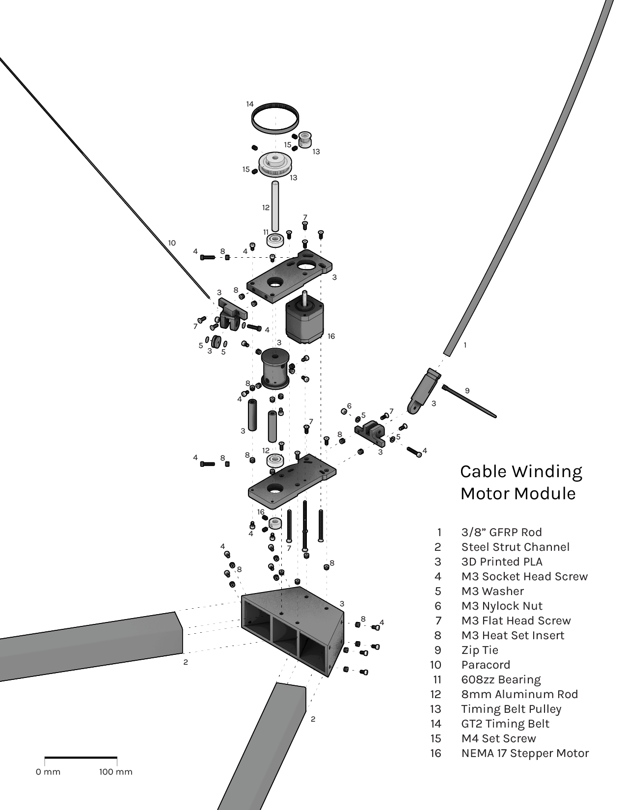
The machine is mostly made from parts I borrowed from a couple of shops on campus (including the GFRP rods and the steel struts I'm using for the base), 3D prints, and off-the-shelf hardware. Lots of threaded heat-set inserts were used. For the time being, this is running gcode on a tinyg through CNCJS
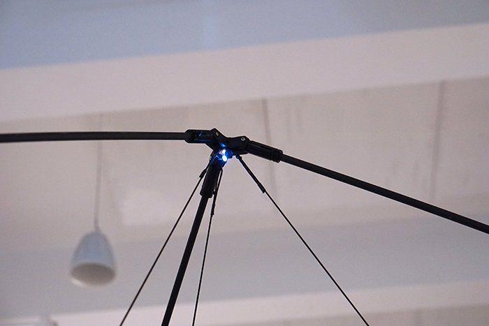
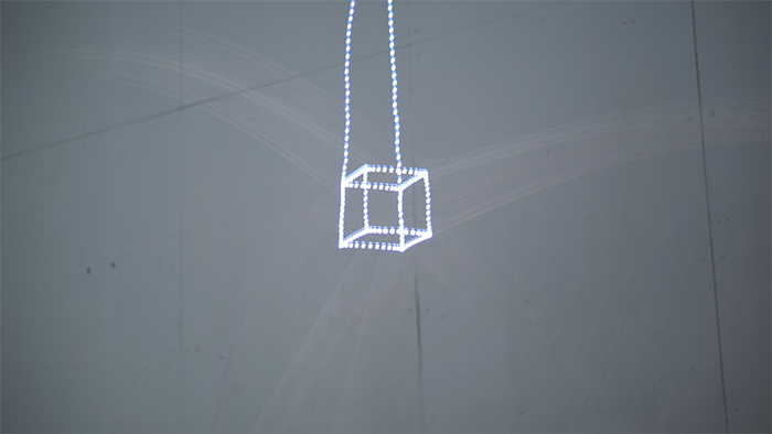
I did not have a ton of time to measure the accuracy of the machine but in order to take a first pass at seeing how much slop there actually is I hooked an LED up to the toolhead and took made some timelapse images. First I had to calibrate settings in CNCJS so that a unit of travel in the computer corresponds to a unit of travel IRL.
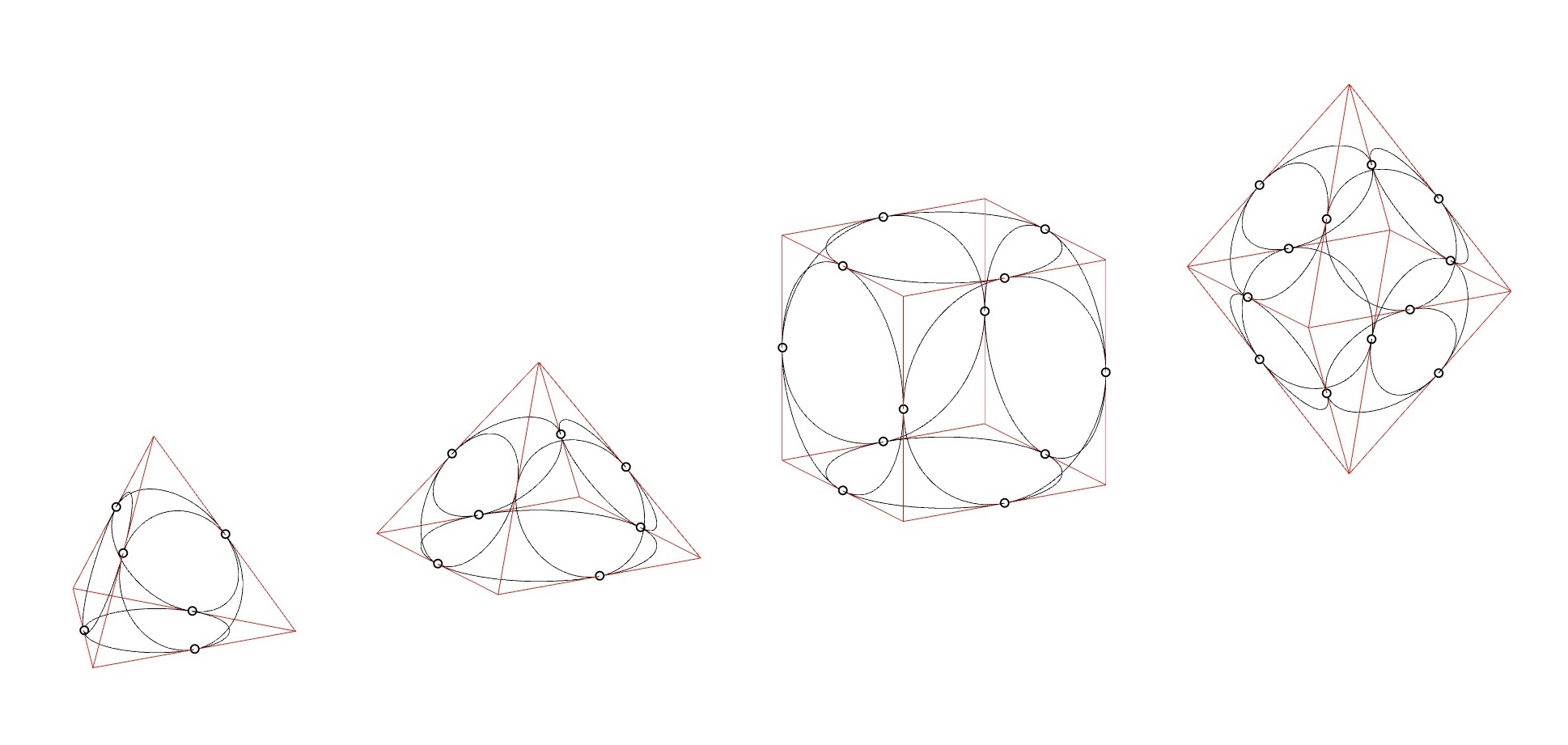
I then made a grasshopper script that starts with an input curve, divides it based on a selected resolution and then takes the points along the curve to calculate the lengths of the three cables needed to reach that point. Then you take the overall starting length of the cable and subtract the length you want to get to in order to find the length you have to travel.
The video below shows me changing a slider in grasshopper to tune the resolution of the path I want the machine to follow.
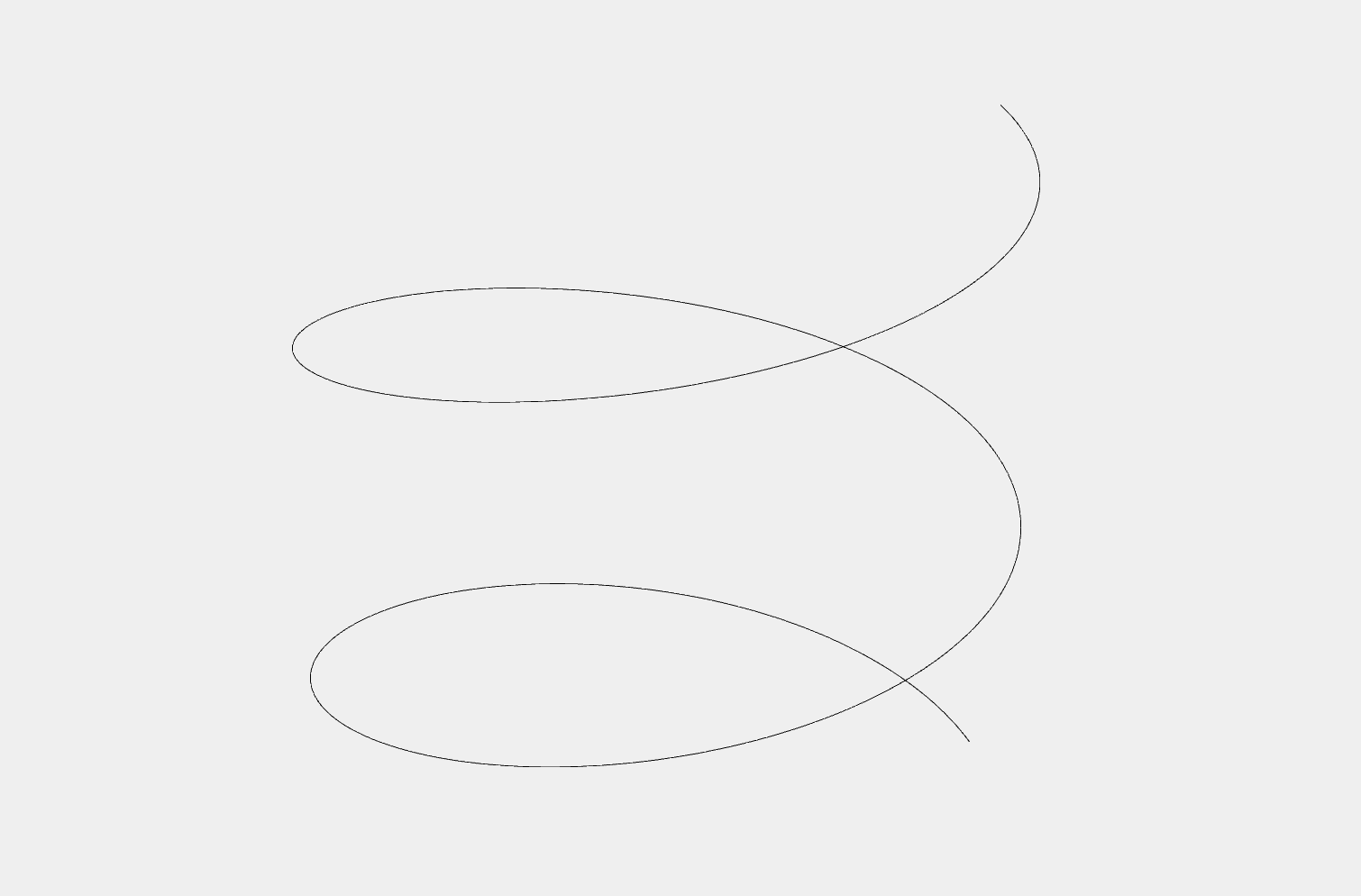
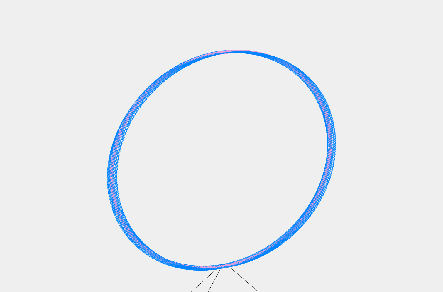
Here is the path it will follow. The cables don't meet at a point, which accounts for the thickness of the path shown.
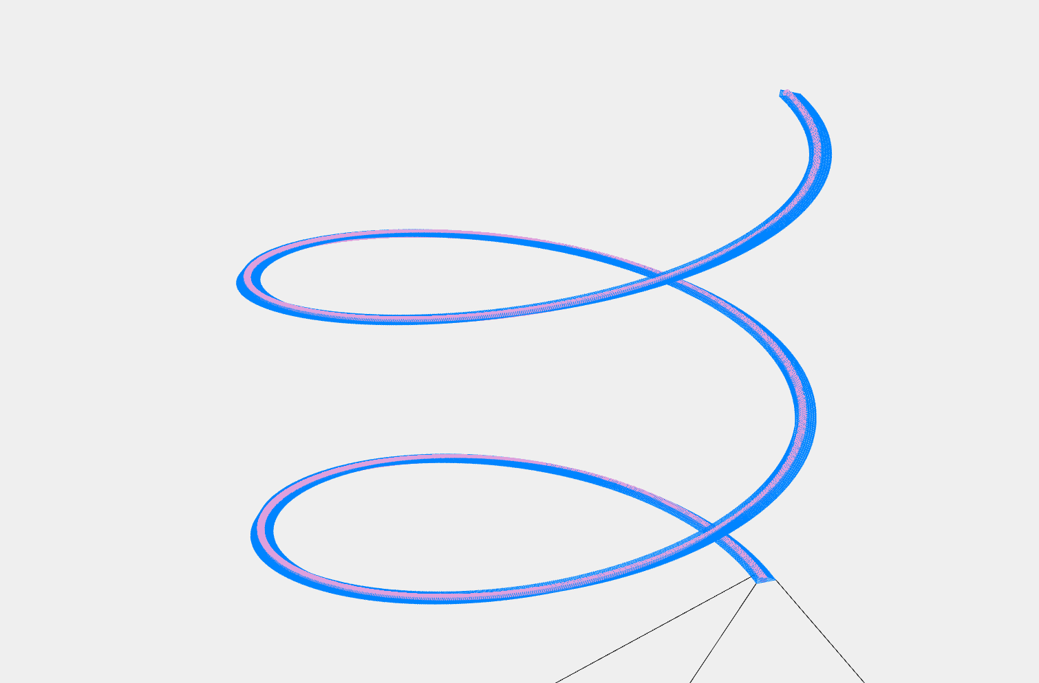
Here is a simulation of the cables following the path...
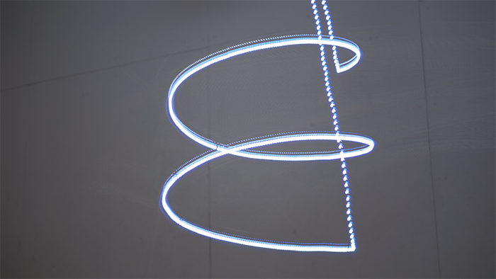
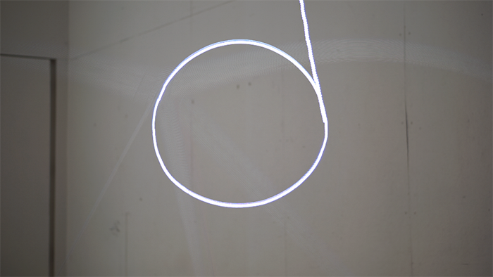
...and here's the path it drew. Kind of works! After playing around with this a bit it is clear that while things are relatively stable in the XY plane, there is a lot of looseness in the Z-axis. Also, the faster it is moving the more it racks.
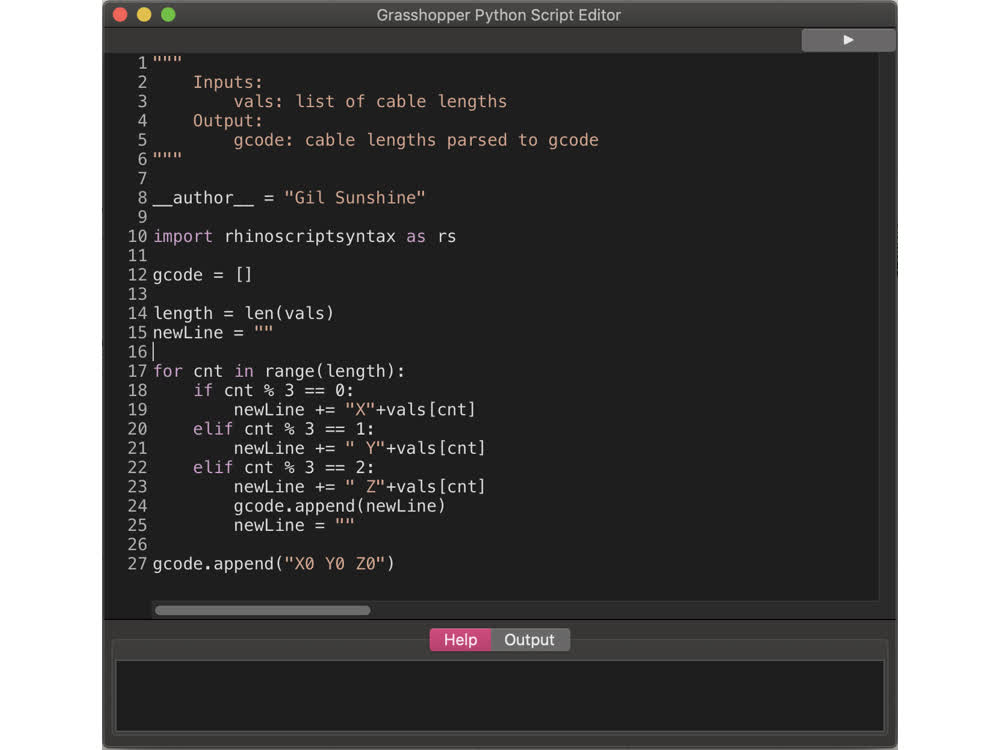
Below is a capture of the grasshopper script which you can also download HERE .
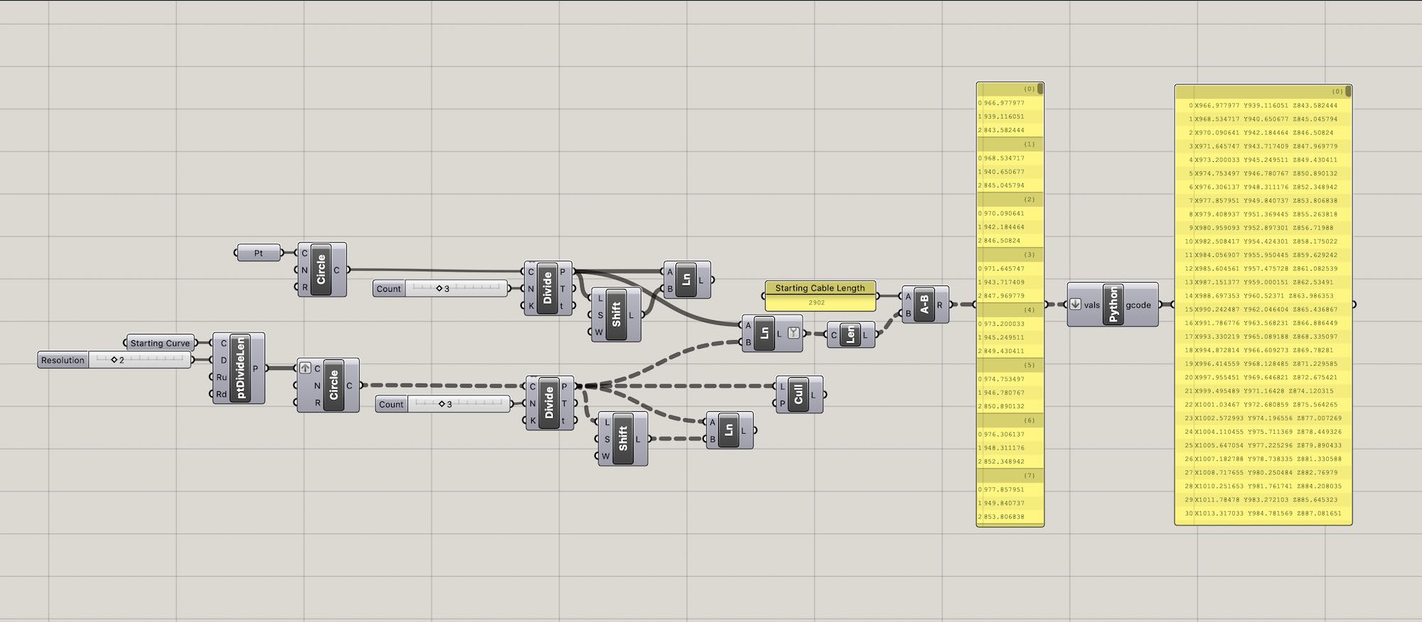
A python script within grasshopper takes the cable movements and parses it into gcode readable by the tinyg. It can then be streamed to a file and is ready to drop into CNCJS.
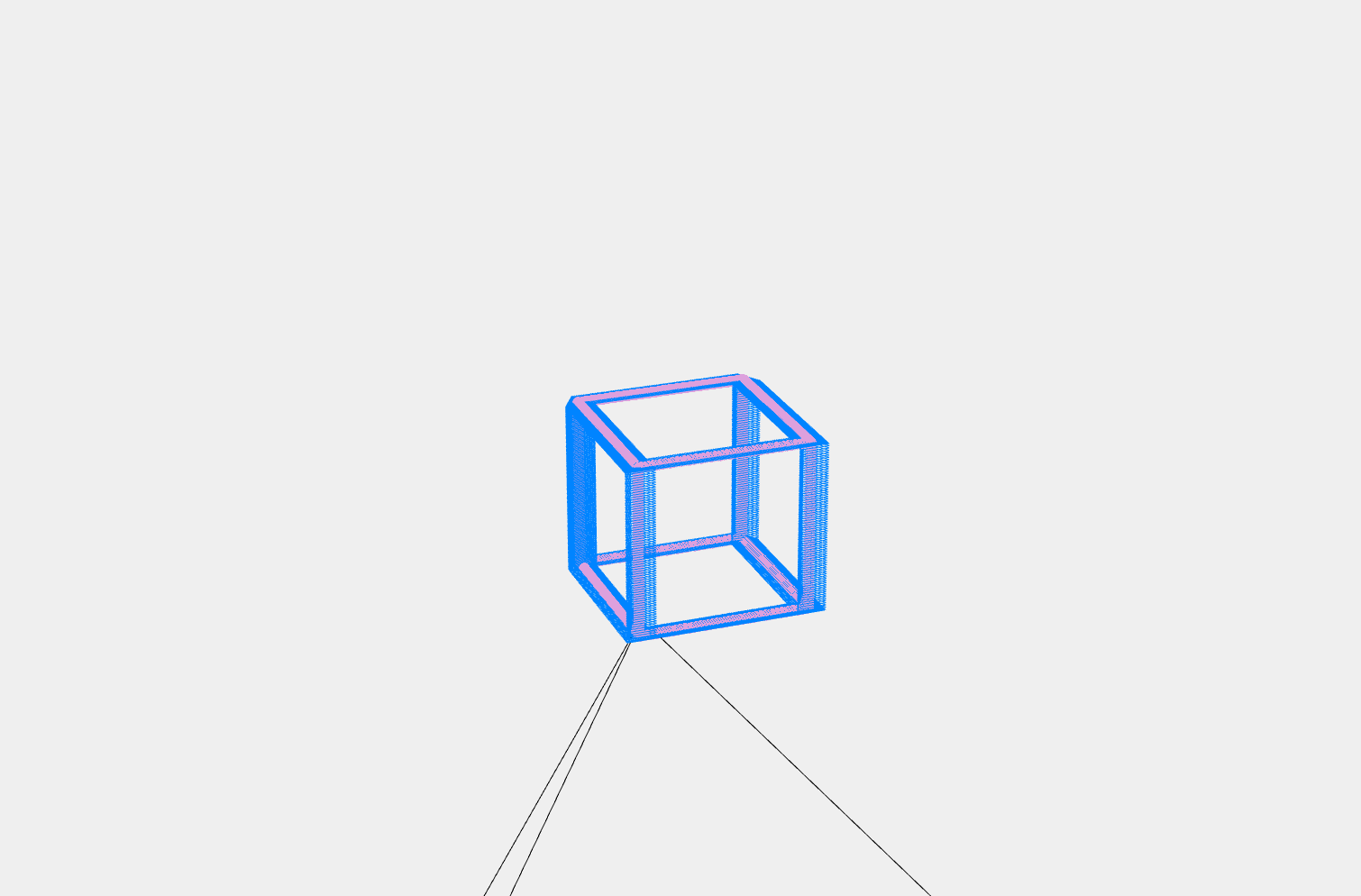
Below are a few more tests. In the circle especially you can see the difference between the accuracy of Z-travel vs. travel in the XY plane.


Questions
How do you maximize machine build area to weight ratio?
How do you make a machine that is easily assembled and disassembled?
Evaluation
Though this machine doesn't really do very much, and it what it does do it doesn't do super well, I think it works as a proof-of-concept for this cable driven bending-active machine configuration.
Implications
A more robust version of this machine could have implications for remote fabrication. Imagine for instance, hooking Laura and Sandy's earth printing research up to this machine, allowing you to print structures with local materials in remote locations.
The scale of this machine also means that it has potential implications for work in architectural robotics in the spirit of Axel Kilian's Flexing Room.
LOG
May 19, 2021 Updates
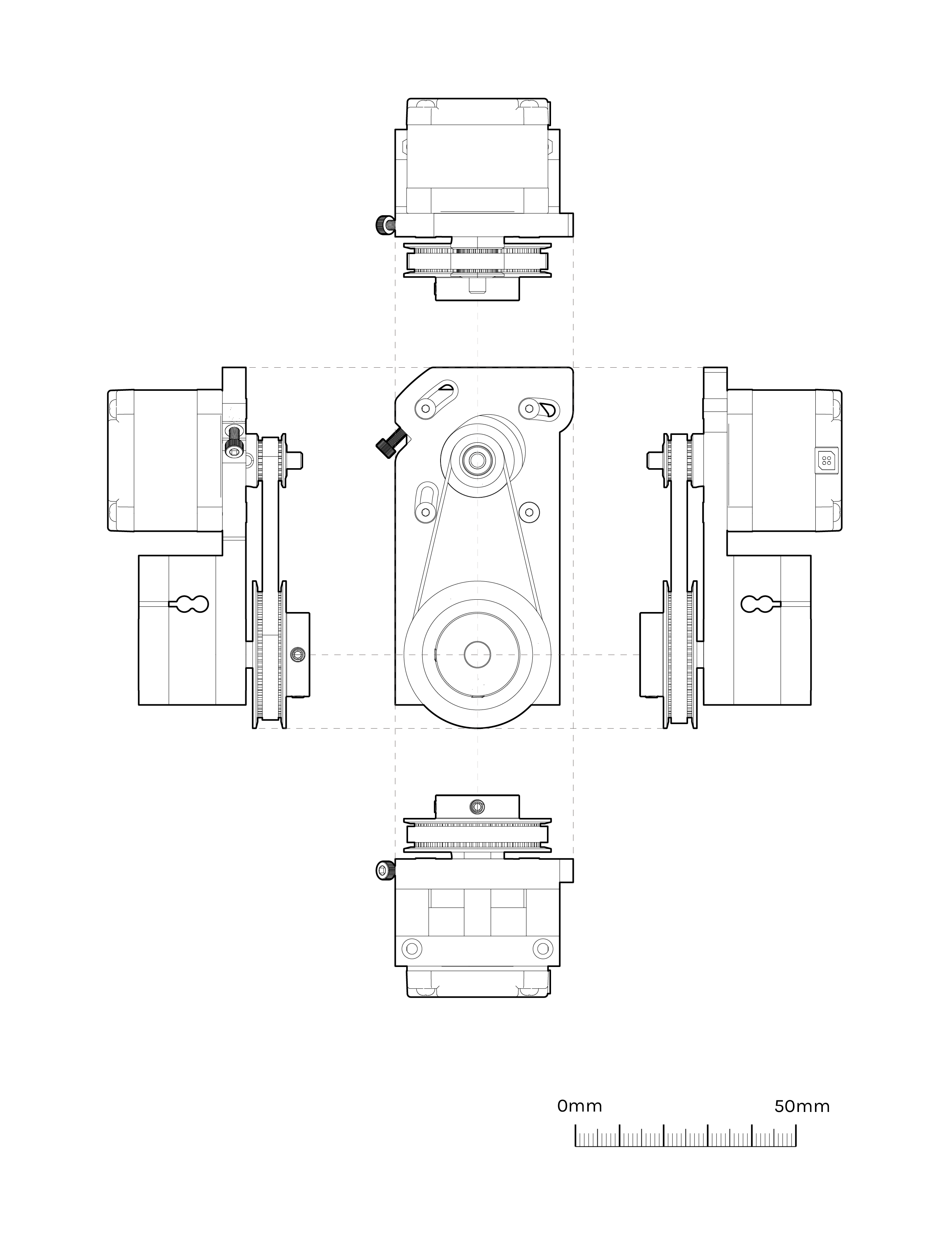
Updates on the Really Big Z. I've continued to iterate on the cable winding mechanism. Much to be improved but it is a smoother ride than before.
April 14, 2021 Updates
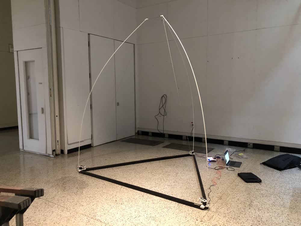
Building off of the early experiments with fiber glass rods, for the past couple of weeks I have been working on a very large machine that I am calling either the SlopBot, 3-Axis Room, or the Really Big Z. This machine aspires to have a really big build area while also being easily transportable for onsite use somewhere remote. One way to achieve this would be with a cable driven robot. The problem with these machines is that basically you need three reliable points somewhere high to set up the machine. The SlopBot is cable driven, but the cables are attached to fiber glass poles, one end planted on the ground and the other in the air. At the moment I'm using some steel channels as a base but one possible variation would be to have stakes that you hammer into the earth that the fiber glass rods are attached to. It's called the SlopBot maybe for obvious reasons, but hopefully I can reel that in a bit. Thinking about adding more fiberglass rods that are not cable driven but just serve to help create more of an uplift force.
Building off of Jake's clank controller, I made an interface using threejs. Note that the bending rods are not shown. The idea is that you can enter coordinations for the "toolhead" at the top of the tetrahedron, the cable lengths needed to reach that point are calculated and then sent to the motors. At the moment this is just for show as I don't have this sending data out to motors. I'm also not sure this is what I will use ultimately (sorry Jake). I would prefer to not use gcode as it doesn't make a ton of sense in this application but we shall see.
Below is a video of the machine in action. I should note that I am simultaneously thinking about this as a robotic architecture, hence the presence of the body (me) in the video. Hopefully it also helps give a sense of scale.
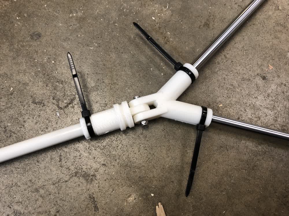
Next step is to iterate on this design. Things got a little hacky during assembly. A big issue is dealing with keeping the cable where it is supposed to be and dealing with the excess cable that starts to build up. This has implications for the controls too as the thing that the cable is being wound onto effectively gets bigger over time. That said, there's a lot of give in the machine at this point so the error that this causes is the least of my concerns. The joints are the biggest concern.
Does this machine make any sense? I'm not sure, but the weight to build area ratio is intriguing to me.
March 25, 2021 Updates
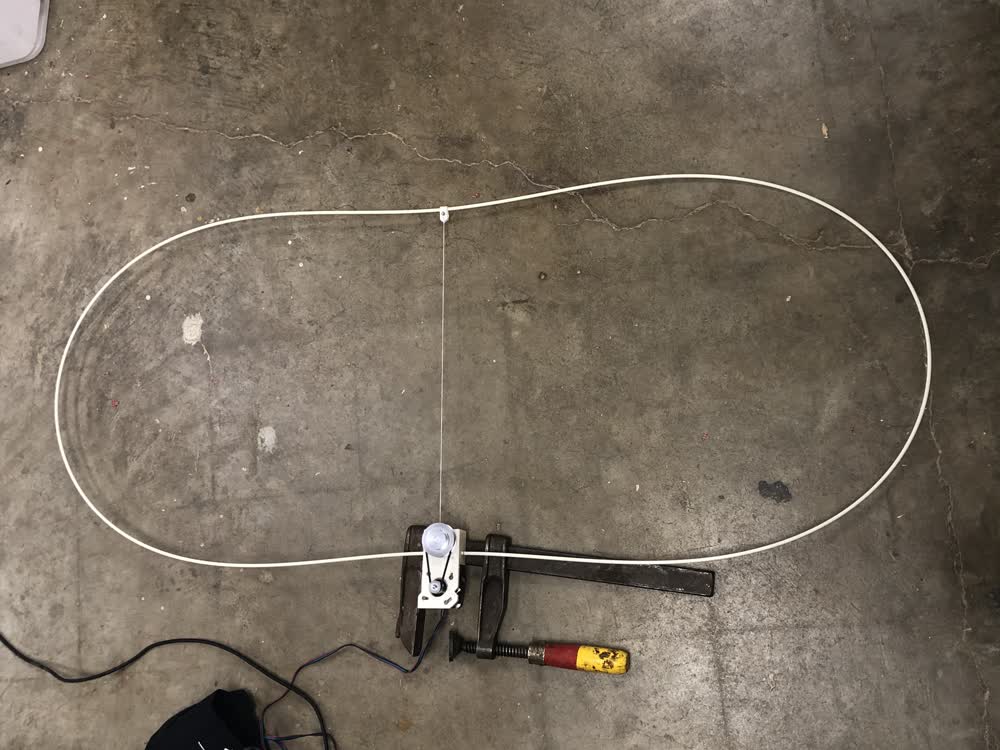
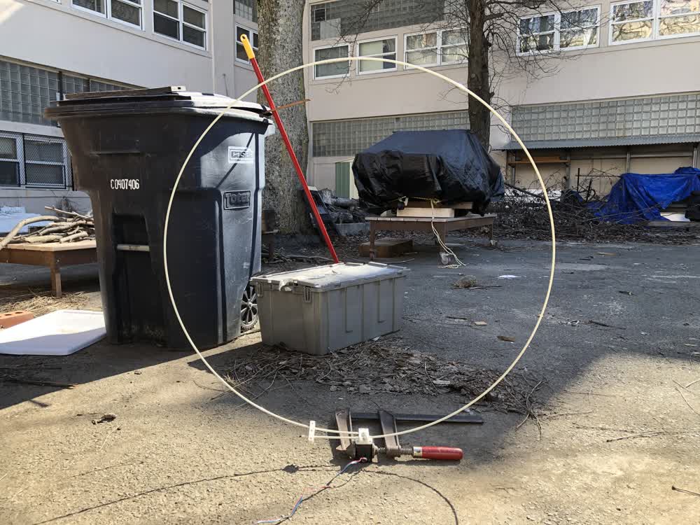
Testing out a new way of making motion this week. I made a new module that winds a cable to change the shape of a fiberglass loop, rather than changing the size of the loop like last week. One can imagine making something that locomotes from the flexing of this springy system. Next I plan on combining multiples of these loops to see what types of motion I can create.
March 17, 2021 Updates
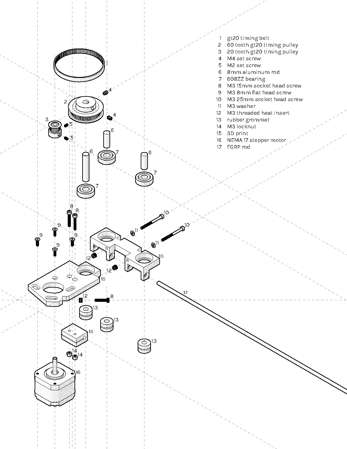
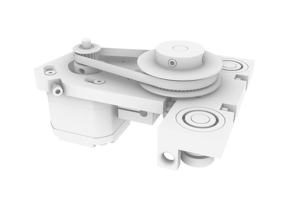
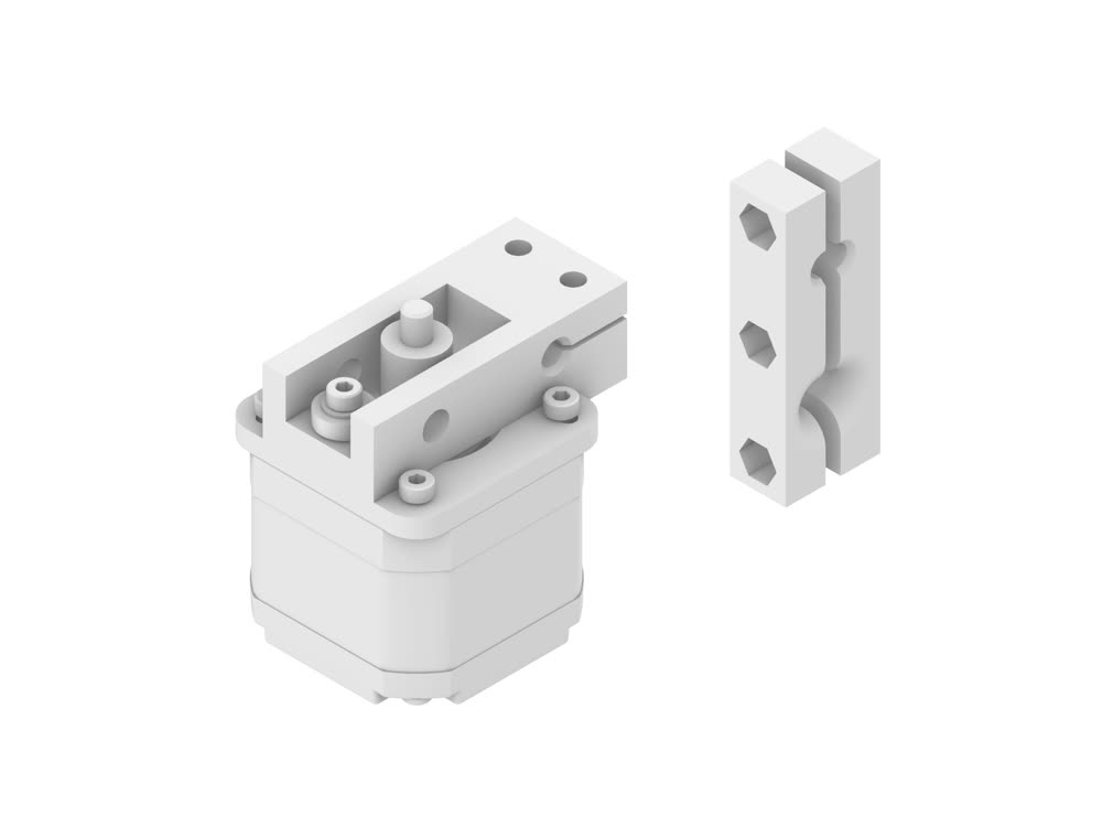
This week I iterated on my fiber glass rod feed mechanism from last week which didn't work so well. There is definitely still much to be improved but I've got rods moving! I'm using a timing belt and set of pulleys for greater torque. I think more importantly I'm using some rubber grommets I had instead of the gear. I've got two idlers as well, so the fiber glass rod kind of weaves between idler grommet, grommet connected to motor, and idler grommet. This module has a lot of give at the moment, which is good in some ways but a stiffer, more robust design is going to be better for longer term use. I plan on making the next iteration of that this week.
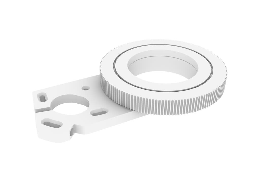
This week I also started developing a module for marking tubular elements of various diameters. This is sort of a Frankenstein design borrowing from Jake's a-axis and a 3D printed slew bearing design from Christoph Laimer. Ultimately you can imagine that the feed and the marking mechanism would be combined.
Neil's comment at the beginning of the semester to me was that it would be good to think about how to automate the assembly of the fiber glass rods I am using. One possibility
I
have been thinking
about
is
bundling
pieces
together a la
Anton Alvarez. This could also be done more like the Fiberbots
from
Mediated
Matter Group.
Either way, a rotary axis like this could be helpful. One challenge I have been thinking about is how you could perform this kind of bundling on a loop where you can't just
slide
the module
through.
Something
to
consider.
March 10, 2021 Updates
This week I made a scaled up version of my rattan feed mechanism to test with some 3/16" diameter fiber glass rod. Sort of knew this wasn't going to work but gave it a shot. The gear on the motor shaft ends up just chewing through the fiber glass rod as it spins. I need to use a high friction material and more pressure to pull the fiber glass along. I also may need more torque but it's a little hard to tell at this point. Probably a gear box or something more custom is in order.
March 04, 2021 Updates
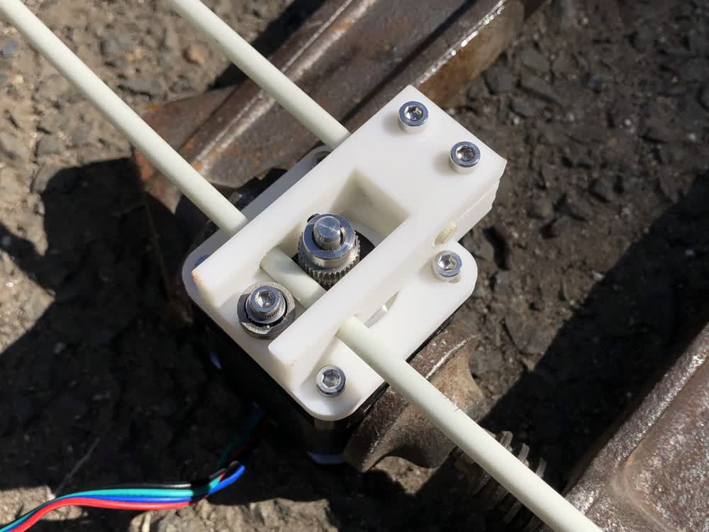
This week I slighty modified my feed design from last semester, which is based on a 3D printer's filament feed. This is really just a first step to start experimenting.
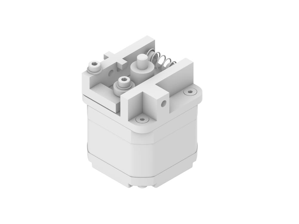
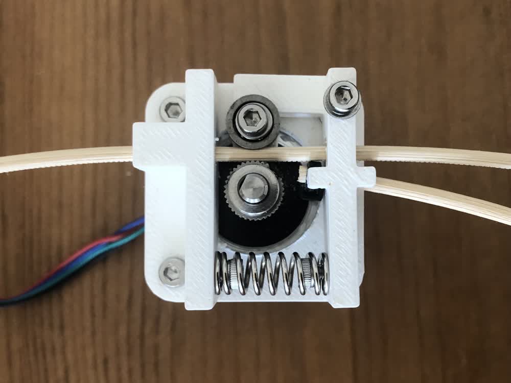
I have one of Zain's TinyZ machines for his studio. To start getting things moving, I'm using the motors and TinyG controller from that machine. Next steps are to start testing fiber glass rods and to start developing modular controls for the motors.