21.04.01 Tiny Z Progress
This week included more updates to the Tiny Z. While the TinyZ is generously designed to be mostly comprised of off the shelf hardware, there are a few custom made parts that need to be made. So this week Maryam and I learned how to go through the water jetting process available at the school of architecture shop. The stock we are using for the tinyZ is 1/4" thick aluminum (by the way, the Omax software for the waterjet annoying only takes files in standard not metric).
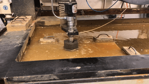
Please see gif above of very murky water bubbling. It is somewhat surprising that this quiet machine can cut materials like metal, plastics, stone, glass, tile, etc. etc.
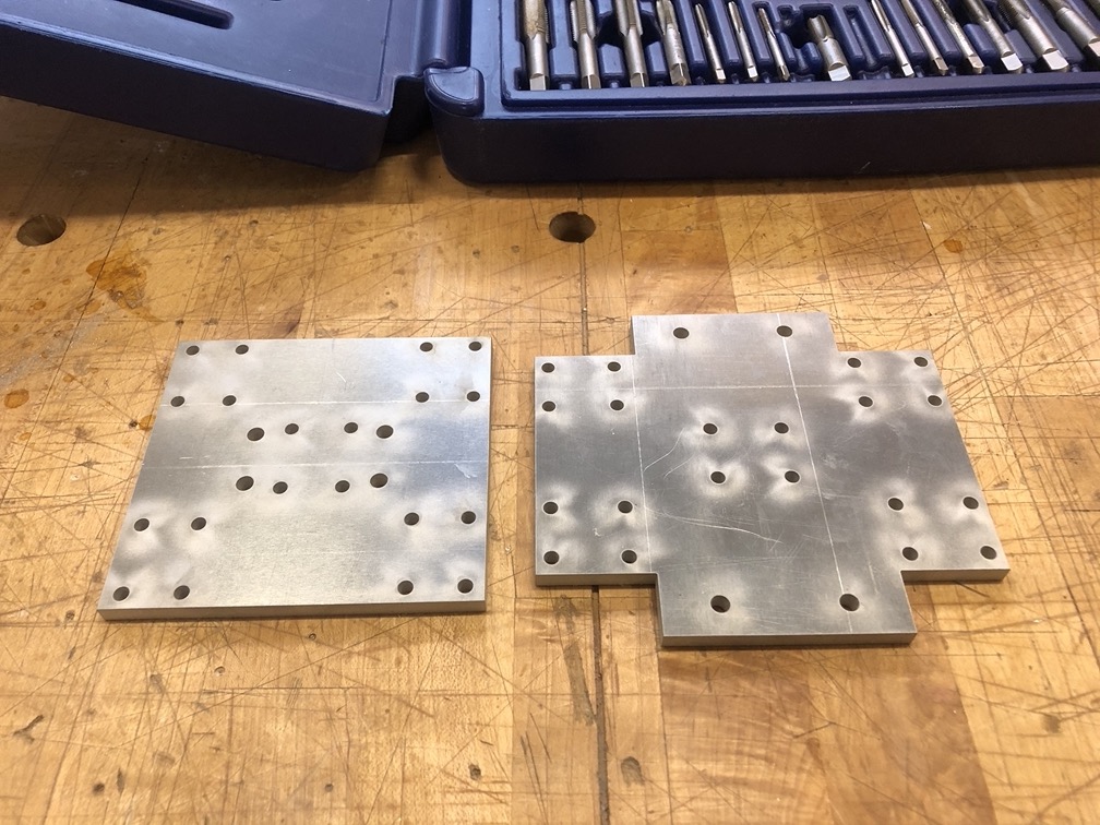
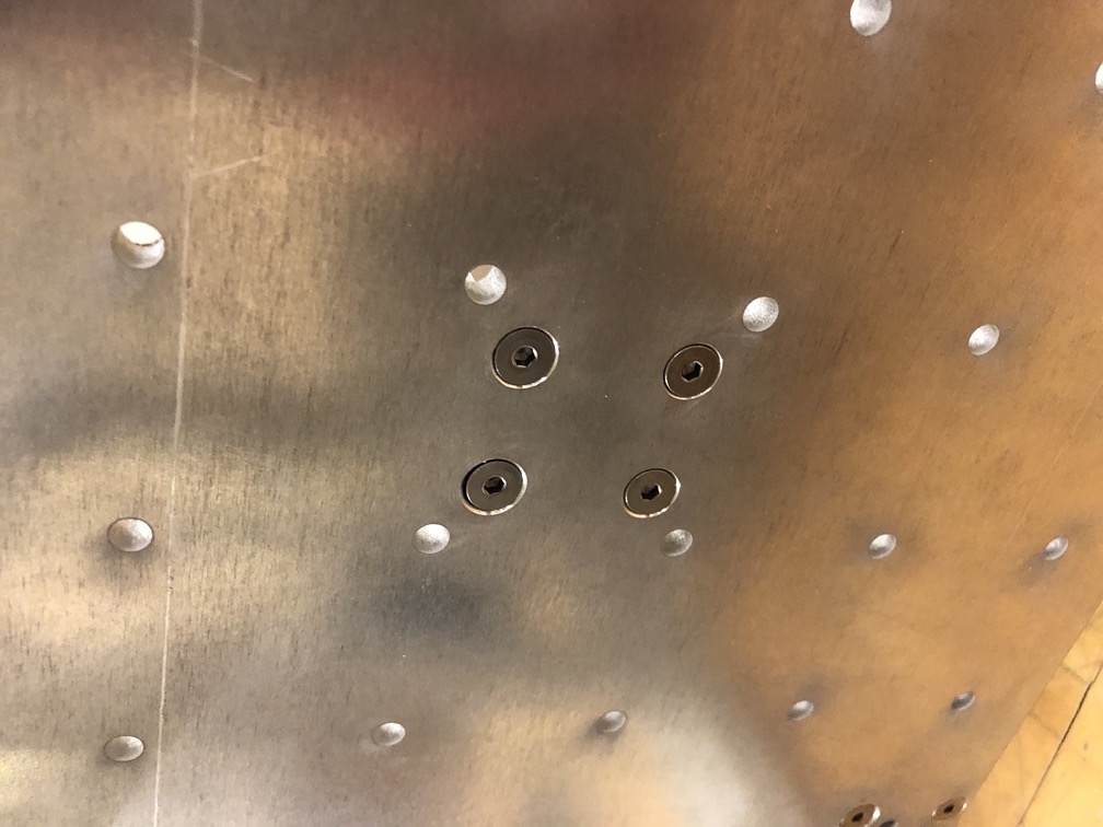
Here are what some of the plates look like after cutting. These plates essentially perform three very simple functions. To hold the lead screws to each axis, to hold x and z together, and lastly to provide a bed surface on the y axis.
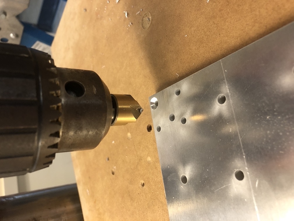
There are two sets of holes on each plate with different diameters. There is an M4 diameter which connects the plates to the lead screws and rails, and then there are M5 diameter holes that connect the plates to the aluminum framing just as everything else on TinyZ is connected. We used M4 Countersunk screws so that the bed of each plate would be flat and free of catching on other moving parts, so all of the M4 holes needed be countersunk manually on the drill press.
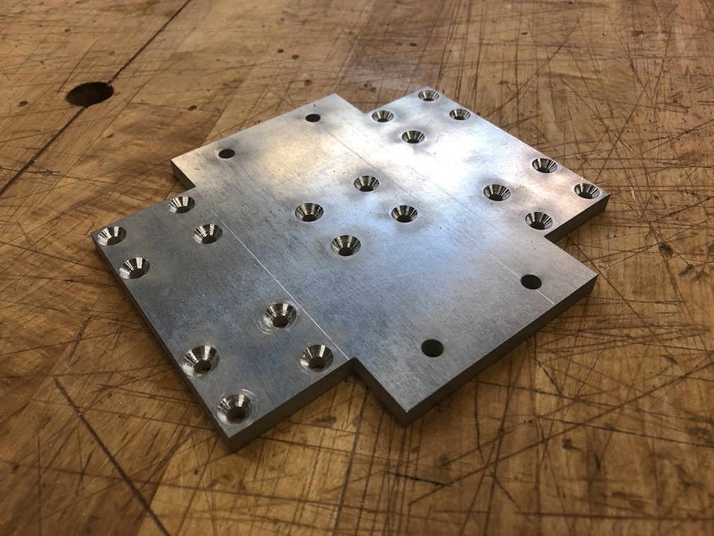
Here is the "cross" plate of the Z axis after all the M4 holes have been countersunk.
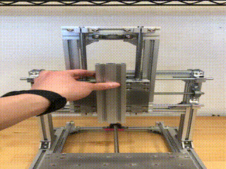
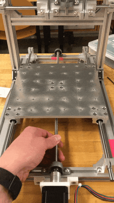
After all the plates have been connected to each axis framing, connected to the rails, and then assembled all together again - all three axis are finally free to move in their intended direction. However the lead screws are not connected yet, hence the crazy sliding motion, and also we must actually add the Nema motors to the machine.
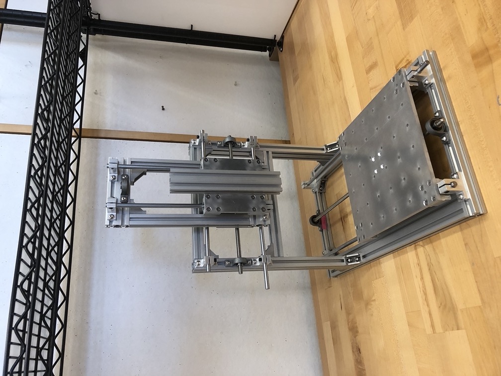
Hunk of aluminum (TinyZ) minus stepper motors and power supply.
Each lead screw connects to the center of each plate respectively through a nut housing with (4) M4 Countersunk Screws.
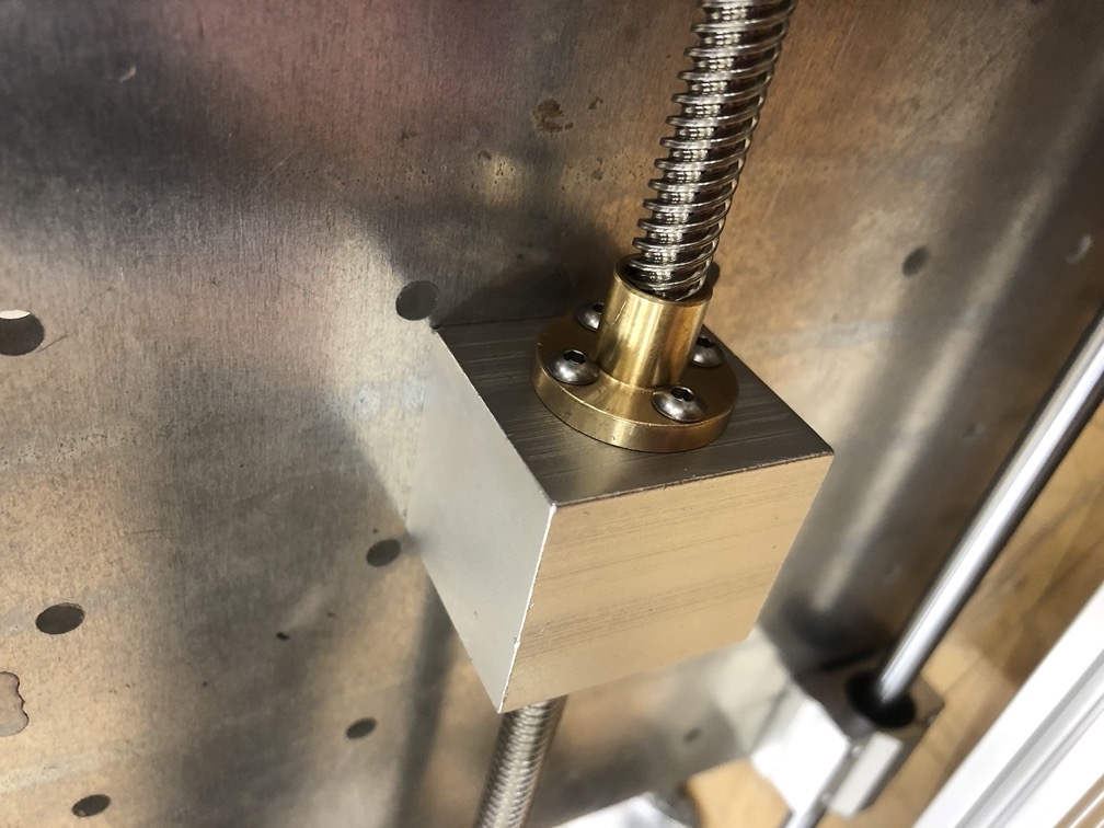
This is the underside of each plate and the nut housing, which is essentially just another hunk of aluminum. The brass piece is what actually connects the nut housing to the lead screw and each axis. These are the M3 screws. We have also opted to not use an anti-blacklash nut here, which if I understand Jake's explanation of what an anti-backlash nut actually does, it would just give us a little more precision in our TinyZ. Maybe it will be an upgrade later.
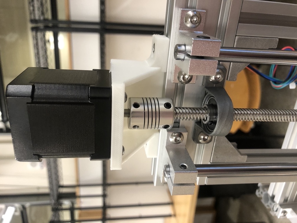
Here is how the motors actually connect to the lead screws to power the movement in TinyZ. A 3D printed bracket screws into each Nema motor with the M3 screws, and then the brackets simply slide into the aluminum framing with the M5 BHCS and T nuts just like everything else. The steppers have a "D" shaft for the set screws of the couplers to tighten against.
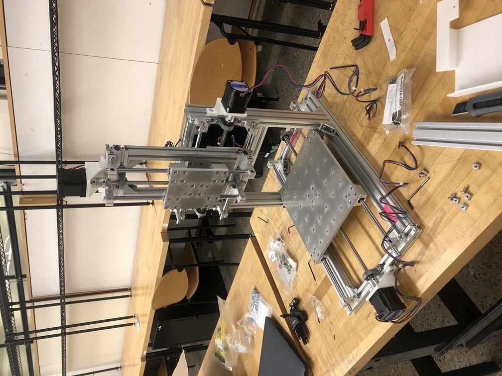
Here is TinyZ with all 3 Nema stepper motors attached.
Finally, the TinyZ is ready for power and actuation!