back
project page for 2021 MAS.865
- bad spooling: the string gets caught on the edge of the spool or at the pivot point. results in slipping, inconsistent spooled lengths.
- the interface at the pen and the paper preventing (typically) the yarn from unspooling. moving the paper down (drawing upwards) is very inconsistent as a result.
- other systemic problems, e.g. the paper is not stiff at all
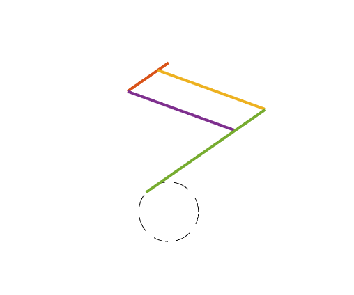
- l0 = 0.0194
- l1 = 0.0514
- l2 = 0.0548
- l3 = 0.09103
- the sub section of l3 opposite l0 is 0.0129
final project documentation
This project is concerned with what are tenuously drawing machines. (A somewhat late in the semester pivot)
For reviews, I worked on Fiber Processes which could tie into currently hiatused work on wet spun fiber extrusion, but this is not at an interesting place right now, so instead: cardboard machines.
question/motivation
The original motivation behind this project was to see if I could build a machine using the tools and materials that were available to me off-campus that would enable me to have improved CNC control over some process. After doing some inventory of what was already around (a lot of cardboard and terrible hobby DC motors), I pivoted toward an exploration of what kind of machines can be made from distinctly non-ideal parts. Some existing reference points would be the 2014 Nadya Peek's cardboard stages and the 2009 Ilan Moyer's foamcore CNC, though importantly these two projects both try to produce something usable or with prototyping value, where I am mostly shooting for arguably educational value and absolute bare minimum functionality.
"machines"
2-axis cardboard thing
The 2014 cardboard stages project uses cardboard to enable faster prototyping of the linear stages and their potential configuration. The linear drive parts (lead screw, stepper, rods, bearings) are the same as what you would use for a stiffer machine.
This 2-axis pen plotter thing asks the question: what if we use 5v DC hobby motors and whatever rotary-to-linear mechanisms that can be made out of string and cardboard?
v1
The first attempt at a functional single axis consisted of two guiderails (semi-polished disposable chopsticks) along which a cardboard carriage was pulled (using some combination of string or rubberbands). Because I was really trying to get this to work with an ungeared motor with an awkward shaft coupling, I eventually settled on using a counterweight system. But! the motor shaft and the string/yarn/monofilament/rubberbands slipped constantly and it was deeply unusable.
tragically unusable
v2
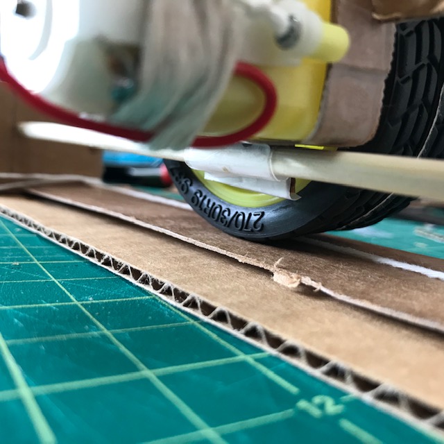
Decide to pivot to using a motor w/ a gear box (1:48 gear ratio) and also a snap on wheel. v2 of this consists of a single guiderail that the motor rests over while the single wheel drives back and forth. To mitigate slipping, string is wound around the wheel and tensioned along the track (capstan effect, e.g. as used here).
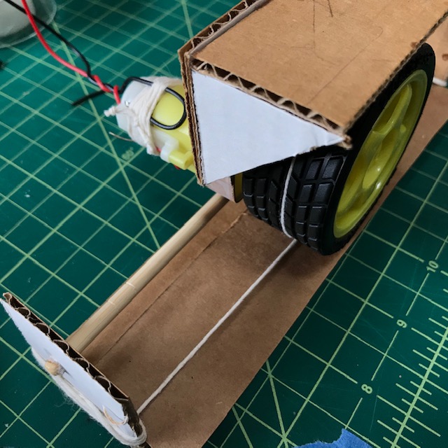
new single axis
motor guiderail mounting
v1.5
While struggling to get v1 functional (and before I found the gearbox), I realized that if I wanted a second axis, the design would need to be substantially different. While the coupling between the motor shaft and various attempts at timing belts was bad, the motors do spool yarn in a somewhat acceptable way. As an actuation mode, this requires some form of counter-tensioning or a second motor to traverse back and forth across an axis. The immediate, non-mechanical solution to this is just to use gravity for that.
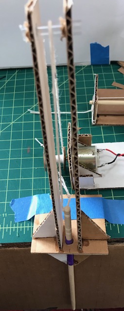
So, we have a spool at one end that either reels in or lets out the string attached to a rod (another disposable chopstick) running through part of a straw for stability.
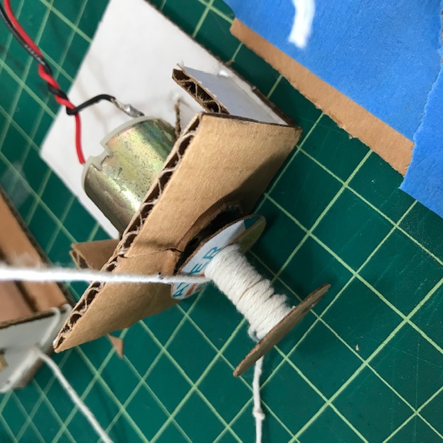
close up of the spool
There is an amount of wobble at the end of the actuator, but it is really not bad (+- 1/4 cm lateral) when compared to the other things that this actuator does.
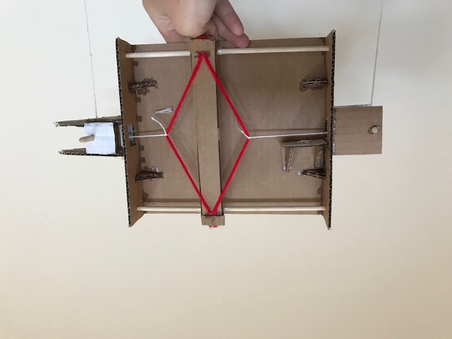
combined version
I used the spooling axis to move a sheet of paper in the up-down axis (let's just say y axis) and the rolling axis to move a pen in the x-axis. This is totally open loop because I don't have appropriate sensors for it not to be and I didn't have time/motivation to try out something interesting for this system. I'm using an Arduino Uno, L298N dual H bridge for motor control, and 7.5V battery pack for motor power.
what a charming set up
here is a video of it running
Not unexpectedly, the spooling axis is the worse performing one. The common failure modes for it are:
to improve the function of this axis, I would add a current sensor to read the current from the motor. I think this would be an acceptable proxy for string tension and help mitigate some of the major problems with the axis. I would also use a different spool (and maybe a geared down motor)--> (larger, narrower spool). As it is now, the axis has swings up to around +-3cm doing the same repititive task when installed with the pen and paper set up.
drift from the rolling axis... everything is open loop haha :c
The rolling axis performs better. It does not appear to slip as it moves, though there is some instability since it is mounted on only 1 guiderail and can tip a bit forward/backwards. (This effect can be somewhat exploited to remove the pen from the paper by jerking the motor). The motor drifts a bit, and seems to do so more moving left peaking at around a 0.3cm difference from its initial distance. The performance of this axis would be improved by stabilizing it (second guiderail probably)(or just weight balanced better, maybe). The motor would benefit from an encoder.
another terrible wall plotter
(but make it worse)
I think there is some consensus that hanging wall plotters are typically not so good, and I have made no moves here to improve their design, only to make it worse, really. I think the primary challenge with wall plotters is one of stiffness/tension and that's not something I'm even trying to address here. I had vague hopes that it would be interesting/possibly somwehat controllable to throw the drawing point around a bit but that didn't work out.
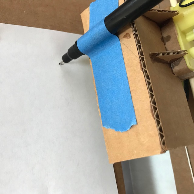
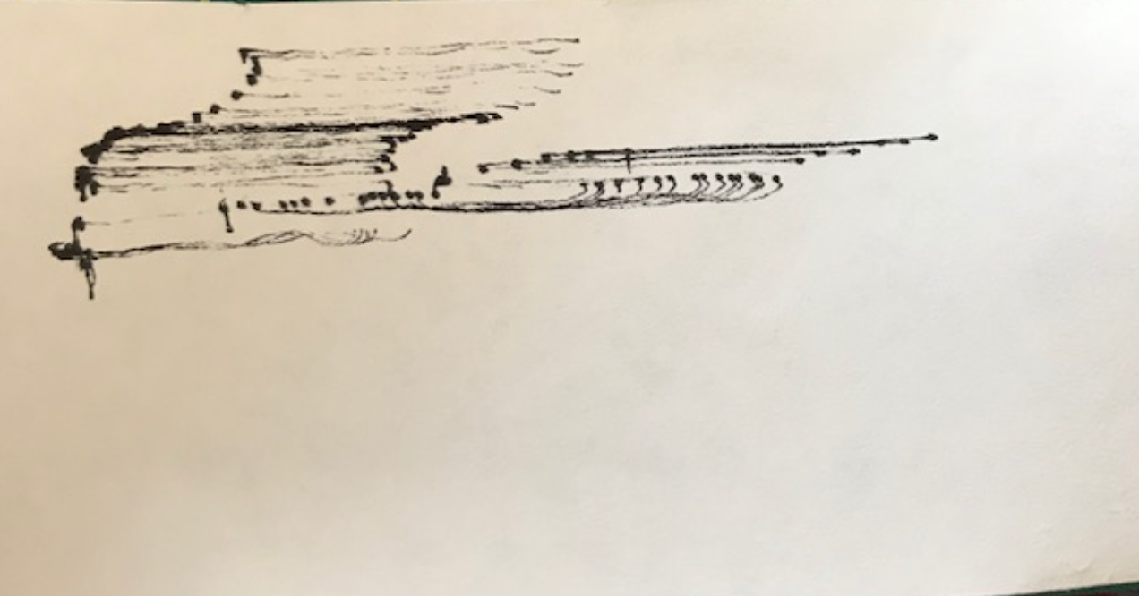
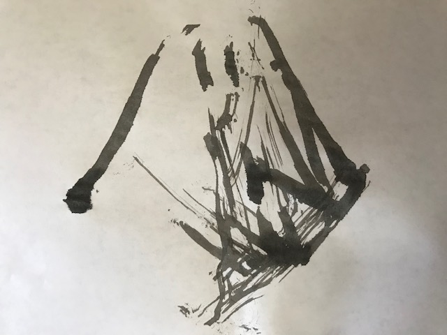
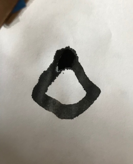
I wanted to spend time on other things and not on improving this, so here's some of the let's call it art that it produced. a good machine for making scribbles. A few quick notes: the issue of keeping contact with the drawing surface is addressed by slightly angling the drawing surface so that it is not vertical, weighting the drawing nib appropriately, and using a sponge/ink combo so that no pressure is needed to make clear marks on the surface.

modular? 4-bar linkages
At this point, I thought it could be fun to play around with 4-bar linkages instead of continuing to struggle with the above.
The 4-bar linkage is set up like a leg with motor actuation at the hip (between l0 and l1). For a narrow band, the end of the leg tracks a relatively linear path.
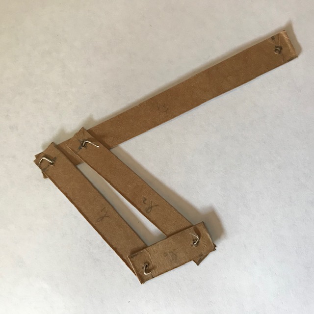
This version is made from cardstock packaging. The joints are done with wire. The individual leg segments are shown below.
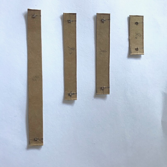
The lengths are supposed to be (m):
The lengths are not actually this. They are accurate to 0.1cm, but since there is give in the wire joints and the cardstock is compliant, the modelling based off the above values will be a bit inaccurate no matter what. This leg was used with the rolling axis for yet another drawing machine, quite capable of making non-representational lineart let's say. A video of this functionality is lower down.
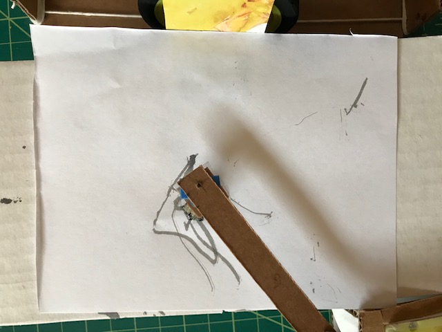
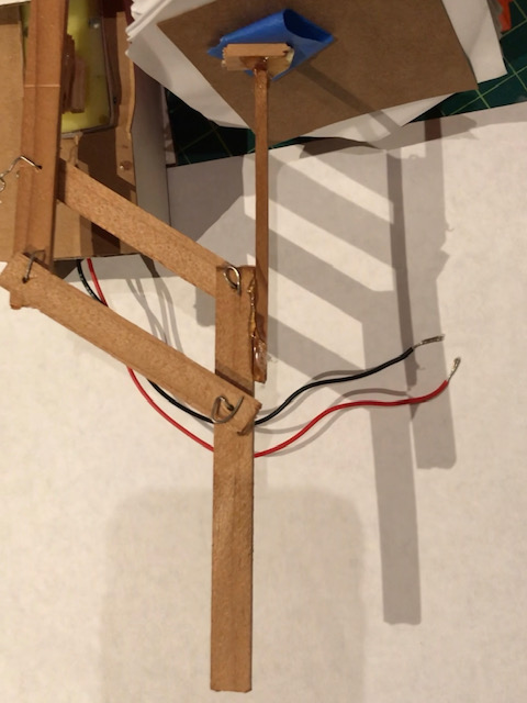
the set up
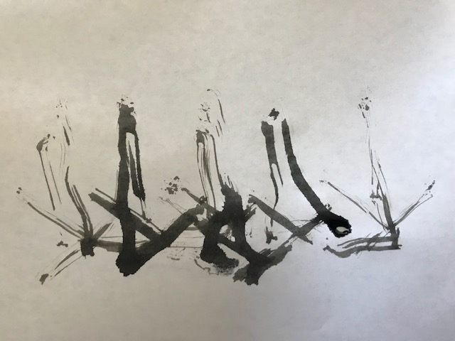
a resultant amorphous shape
An issue with using this as the second axis is that the motion isn't completely linear, though there are two regions that are fairly linear. Also, to note, that the hip motor is meant to go back and forth and not continuously rotate. The way it is assembled, the links will collide and break. Having noted this, the cyclic behavior the leg does is a bit non-ideal. Though it does it quite predictably. Because the leg is made from flimsy material, I could only run it using the ink set up, so the resolution is not completely clear. It is able to hit the width of the ink repeatedly though, so ~1cm.
From there, I was thinking it would be nice to try out some pneumatic actuators. The reasoning behind this is that it would be nice to have control of the hip + a knee joint, but based on the materials available to me and how not well some string+tension systems worked earlier, the knee joint need a light weight actuator. The content from the Additive manufacturing/folding session was very interesting, so I thought I would pursue a folded bellows structure.
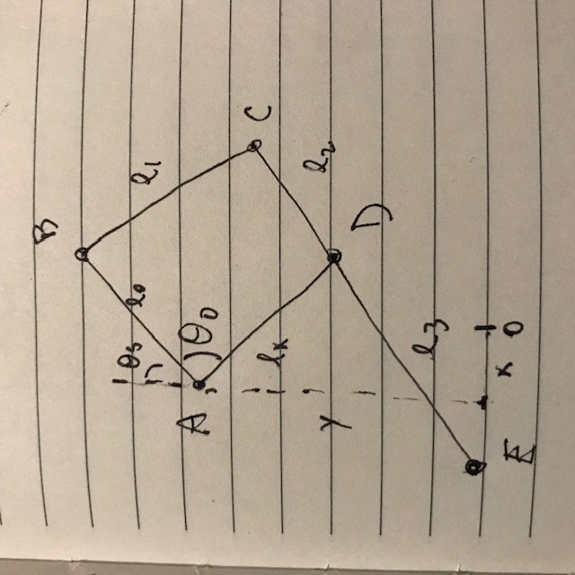
I decided it would go at lx in the diagram above, acting like a prismatic joint kind of... Because of the width of the origami bellows, the leg needed a re-design, so we can quickly go over that here.
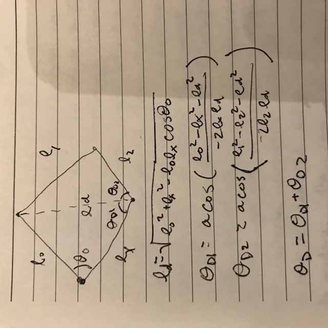
In this formulation, lx is adjustable, while theta0 is fixed. Starting with a simpler version of the leg, with only the inflatable actuator at lx, thetaS is also fixed (the angle of l0 off the vertical). The law of cosines gives us thetaD in terms of lx. For actual simulation, the inverse cosines are a probem, so I generate a range of lx values and the resultant thetaD values and fit (in this situation) a two-term exponential function that is used to explicitly define thetaD in terms of lx for simulation stuff. (based on a strategy from a group project last year).
From that, I get to a little simulation thing
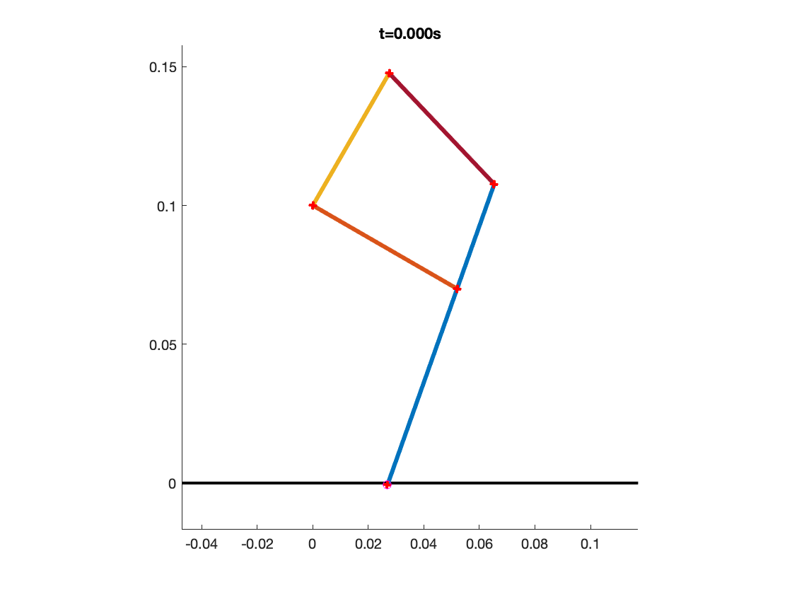
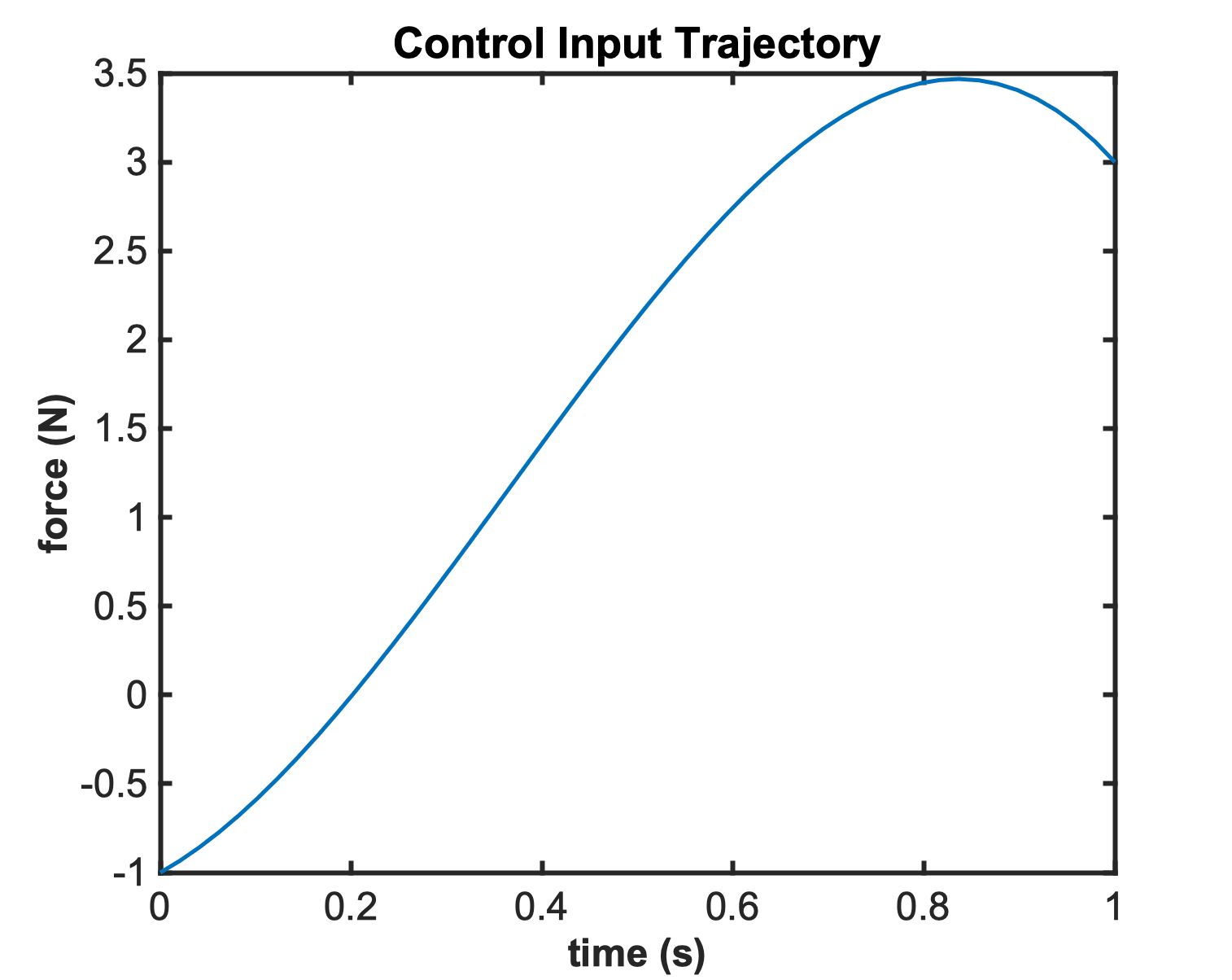
the control input is cutoff at t = 1s, and the leg collapses. Before that, it does a little hopping. The simulation is not super matched to a real system yet, so it is difficult for me to say whether this behavior is a sign of an interaction problem between constraints on ground contact and lx length or whether it is because some system parameter values are a bit nonsensical.
Onto the bellows!
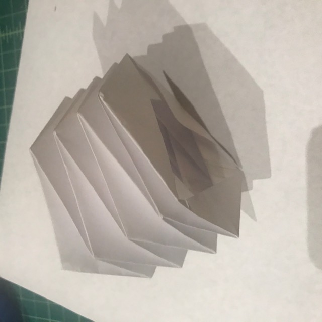
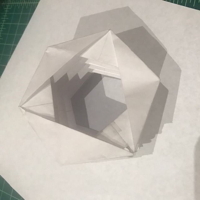
I started with this hexagonal bellows as this person does. I then did a different sized version using vinyl sheeting (which actually folded very nicely) intending for it to be the actuator of choice.
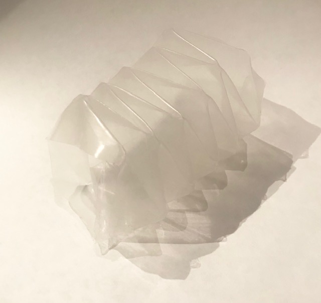

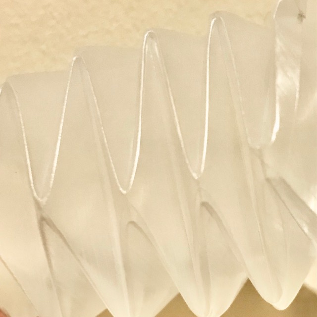
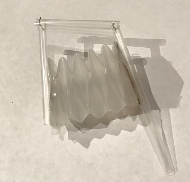
The stiffness of the resultant plastic bellows was higher than expected and it was not meaningfully actuatable with the fan on hand. Howerver, I still stuck it into the 4-bar structure in hopes that I could learn something about its passive dynamics, but I have yet to realize any fundamental truths from this.
I have some optimism that I will switch to an airpump that allows me to pull vacuum more easily and will actually be able to try out the leg. Since the paper bellows seemed a little more amenable to being inflated/deflated, I tried one last pass at getting an inflatable leg working.
The above image is based on something I worked on previously, but using that as a starting point, we can get to more complex movements like the rose plot in the video (simulated w/ PD control). This version pivots to using a parallelogram in the middle as this makes simulation easier and the mechanical path matters less with hip+knee actuation. A motor is placed at the hip. A bellows is placed above the knee and push/pulls on it. The hip swings the whole structure. It doesn't quite work.
From the video, it's clear that the extension of the bellows is a bit discontinuous. This effect seems unique to the larger paper bellows, as neither the plastic nor the smaller paper bellows will pop back open like this. This problem would also be mitigated if push+pull of airflow was feasible with my set up, but right now it's not. There's the additional problem of the sliding of the knee pusher (current solution of loose tape is inelegant), but this is addressable. The hip actuator snapped ~2s into trying it out :( Anyways, full of optimism for this system and would like to try out some different folded structures :)