Week 10
Output Devices.
Engineering Files
Servo Actuation
During spring 2021 in peak COVID times, I was a TA for 2.007, which was the year we had "Pappalardo in a Box". This meant that each student (and TA) was given a full box of parts, tools, and electronics to experience all of 2.007 entirely virtually. I recently rediscovered all of these stashed in a closet, and wanted to use some of the servos provided to do the assignments this week.
We were given around ten Bilda Dual-Mode 25-3 servomotors (link here). These have a "default" and "continuous" mode, and the 2.007 kit came with a programmer to switch the servo mode as needed. The continuous mode was a speed controller, while the default mode commanded specific angles. For this week's assignment, I wanted to try interfacing the PCB board I printed in Week 6 with the servo. My breakout board could still reliably control the servo because it only needed a PWM pin, but a DC motor would most likely have needed some kind of motor driver for the controller.
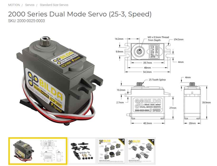
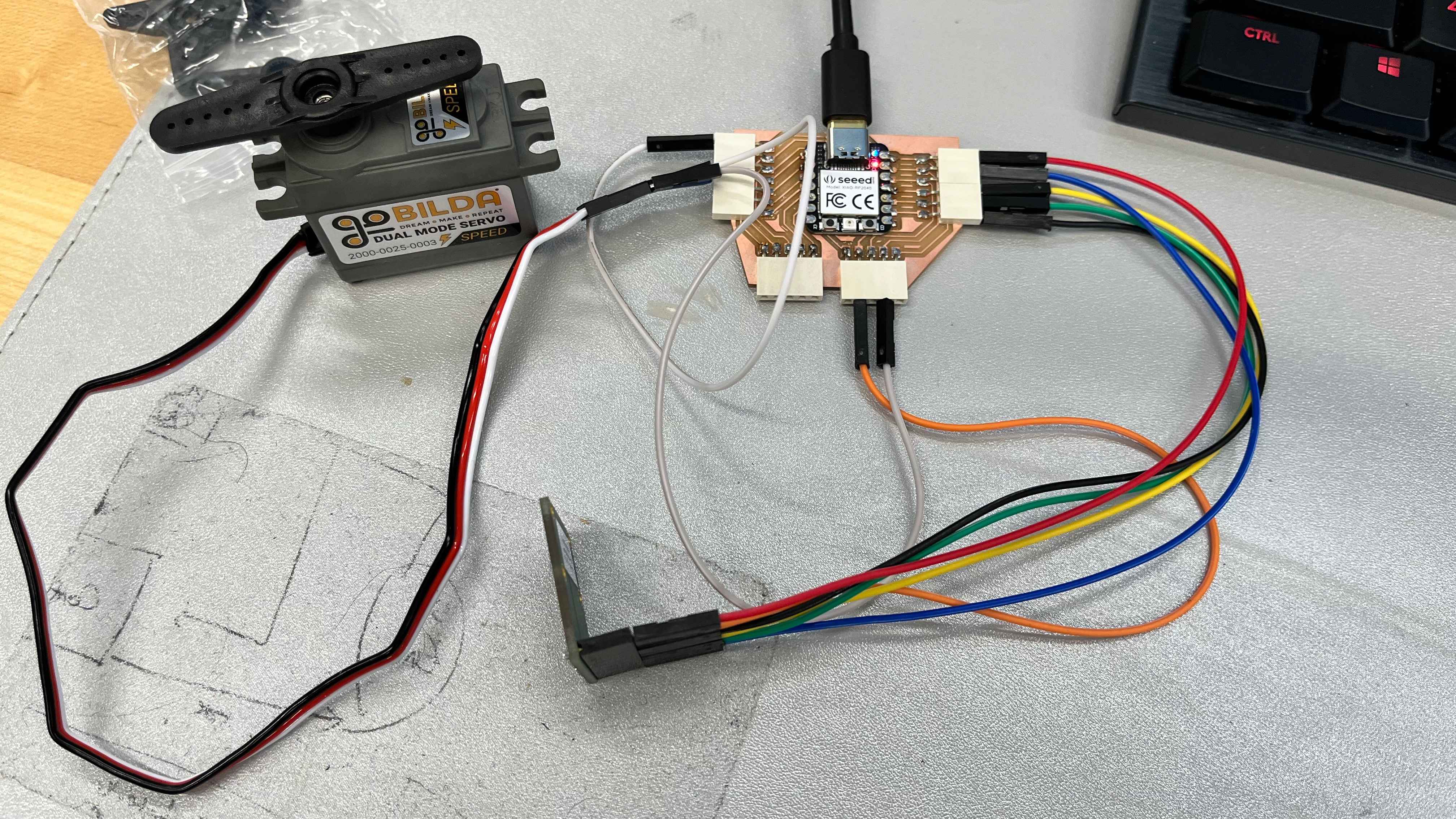
I began by reading all the documentation for the Bilda, and realized that I would be cutting it extremely close by powering the Xiao via USB from my computer (which nominally outputs a 5V and 500 mA). From the spec. sheet of the Bilda servo, stall torques could easily exceed 2000-3000 mA. I decided to try it anyways, being careful not to touch or resist the servo in any way. I wired up the servo and my magnetic encoder from last week to my Xiao breakout as pictured:
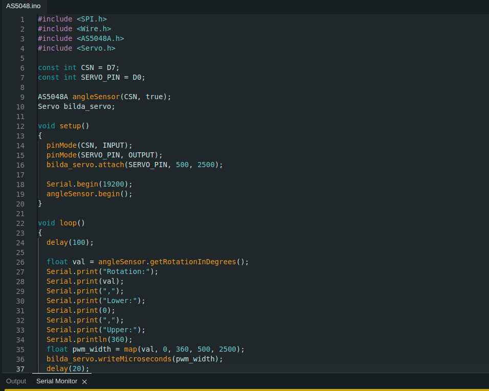
I then used the Arduino "Servo" library to test the range of the servo. I tried initially directly using the "write()" method to command the angles of the Bilda, but found I couldn't make it move to the documented limits of 300 degrees.
I then modified my code to initialize the pin with the specified PWM range of 500-2500 microseconds, and used the "map" function in Arduino to map the angle range of 0-180 degrees to the PWM range. This worked, and I was able to command the full specified range.
With a working servo, I wanted to connect the servo to my magnetic encoder from last week to make a responsive actuator. It was simple to feed the angle reading from the magnetic encoder to be written to the Bilda servo, and immediately the servo began twitching back and forth because of the noise from the encoder. I had to carefully position the magnet so that the readings could be measured accurately:
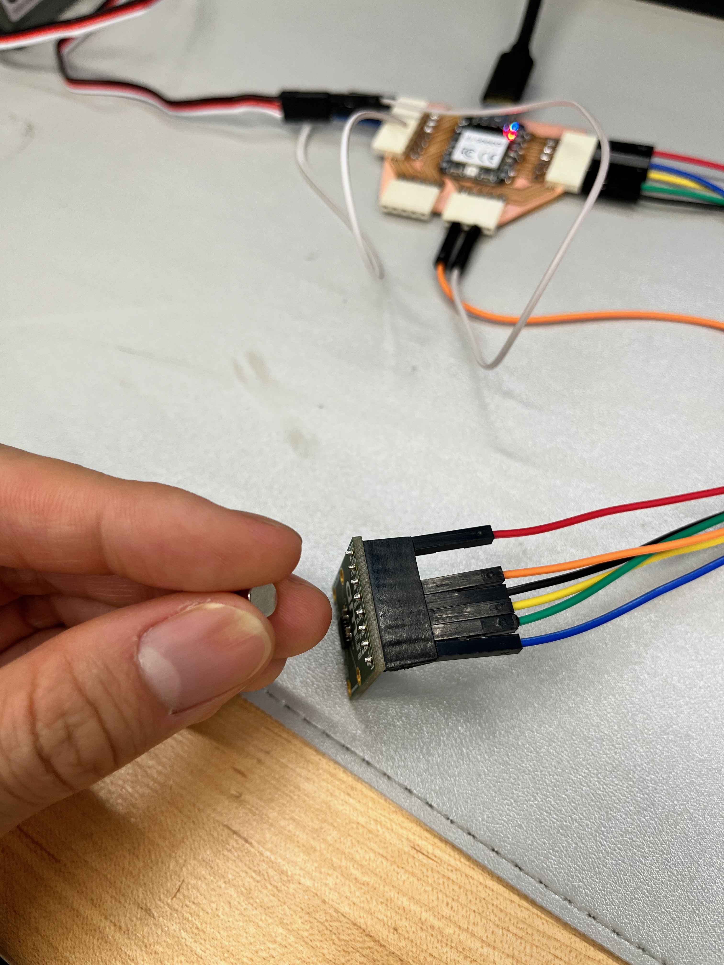
After a little more debugging, I found that I could control the servo by carefully rotating the magnet in my hand. A video of this is shown below:
Lastly, I was curious how close I was to the limits of the power available from my computer's USB port. I originally used a multimeter to probe some of the connections in my board, and use Ohm's Law and power calculations to estimate the current draw. The no-load servo current draw was specified to be around 200-300 mA, so theoretically the USB port would be able to control the Bilda without issue. However, my labmate (a proper EE) saw me struggling and gave me a USB power monitor that I could use instead, which was much more straightforward. The measured current draw was around 150 mA from the multimeter, and the USB power monitor confirmed that the values were close:
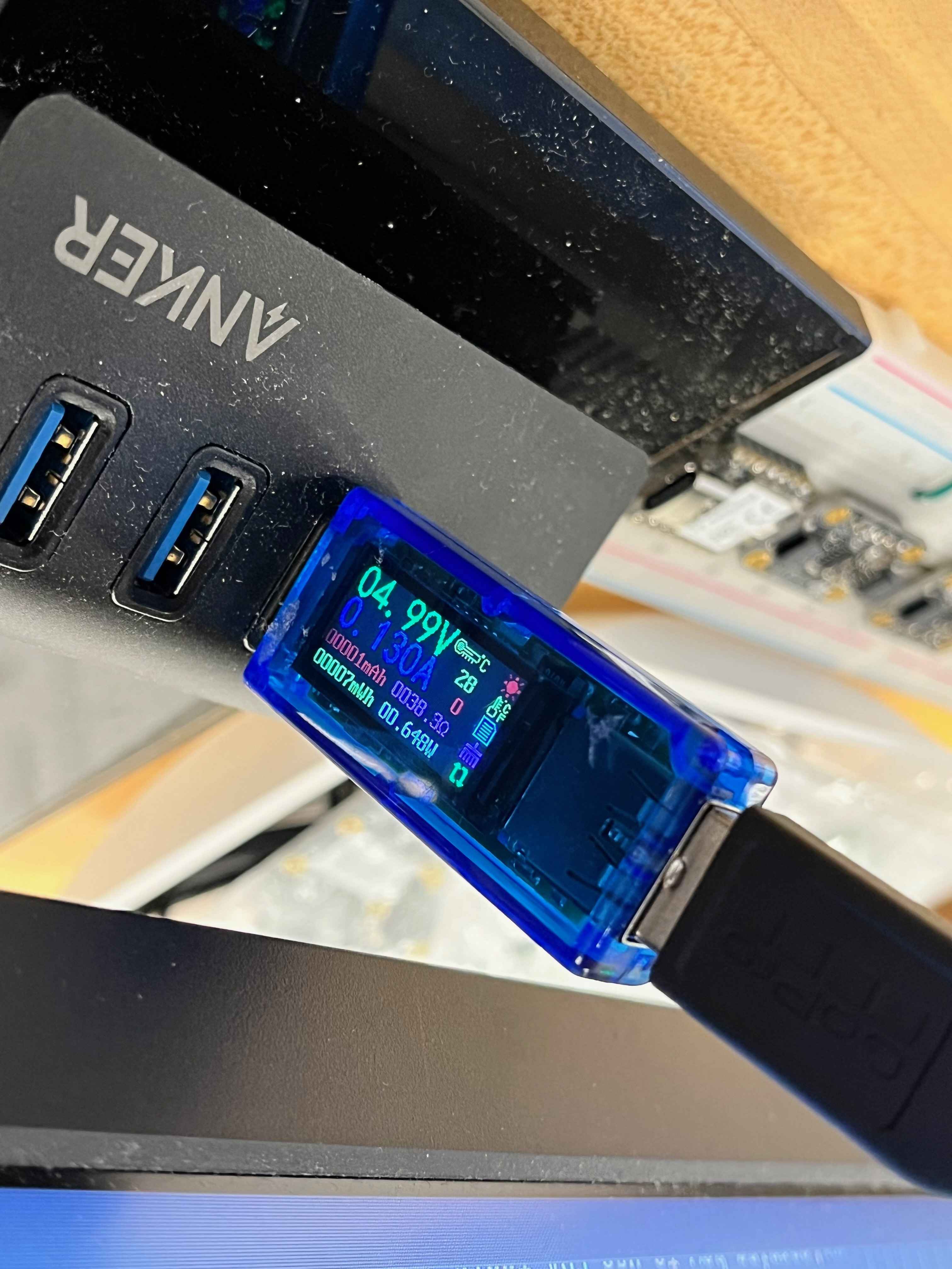
In total, my power consumption from the servo and encoder was around 0.7 W!
How to Make Almost Anything 2023