"Perpetual" Time Keeping
A mechanical watch that winds itself.
Engineering Files
Overview
In brief, my idea is to design a mechanical watch with a tourbillon that "winds itself" from a robotic arm keeping track of the time it's losing.
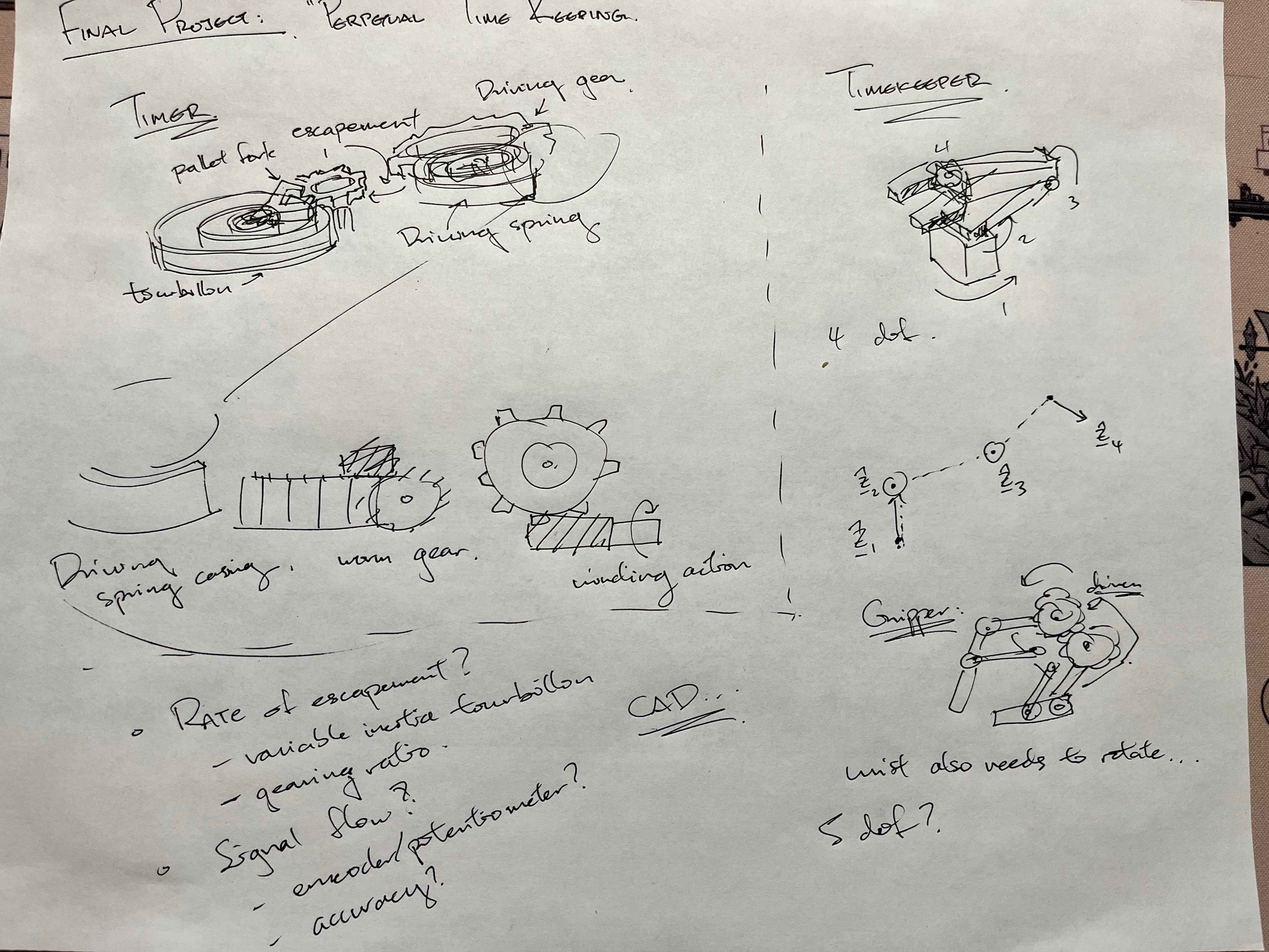
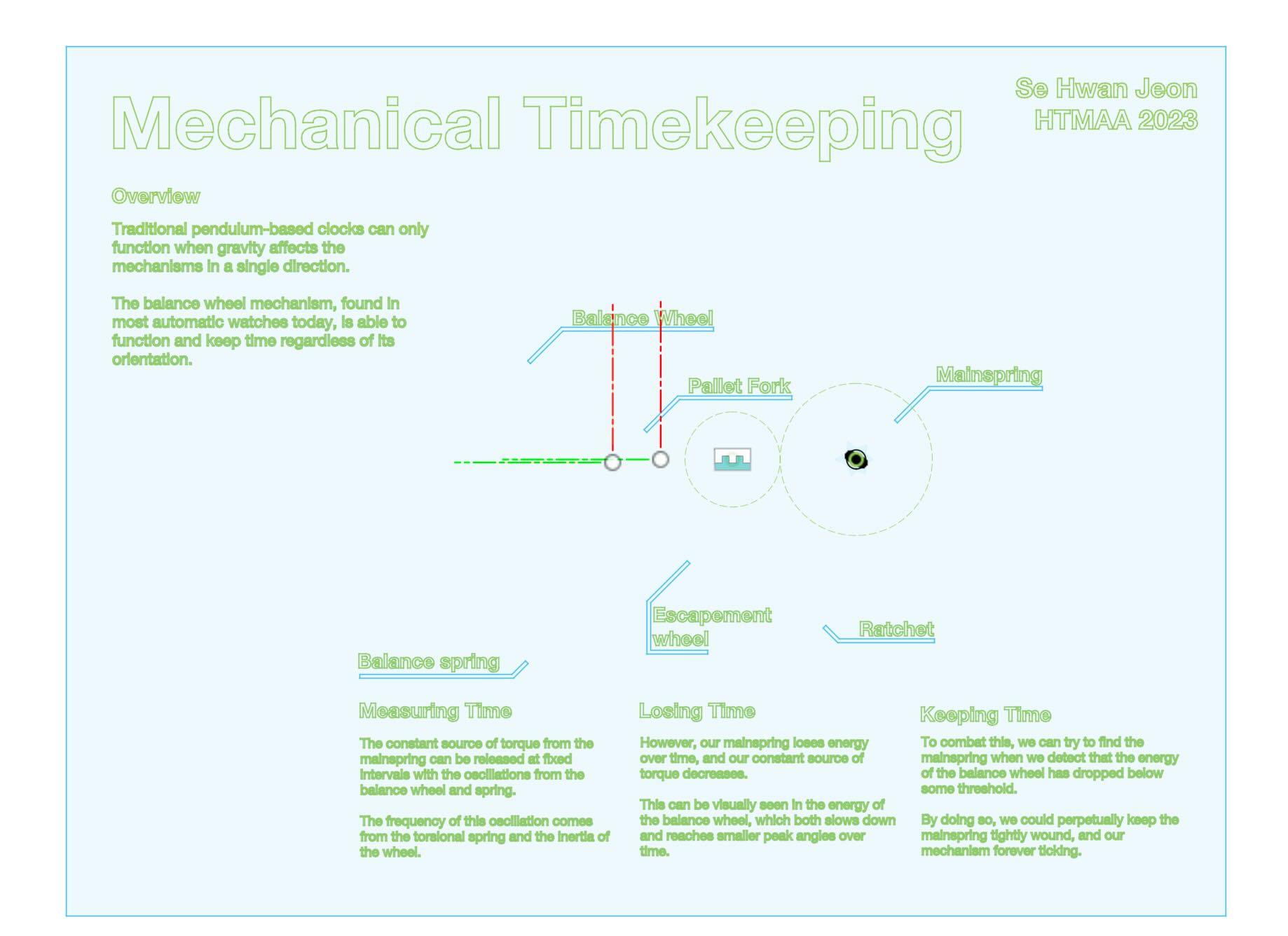
I wanted to be able to lay out and spread the mechanical components all out on a single board (probably wooden?), with etched descriptions and equations detailing how the gears are driven, and what each mechanisms are doing.
The robotic arm will be able to wind the watch by turning the crown, and will be able to keep track of the time lost by the watch by counting the number of ticks of the tourbillon. With the goal of education in mind, I also wanted to add a display to show the phase portrait, time-series, and ticks counted by the balance wheel.
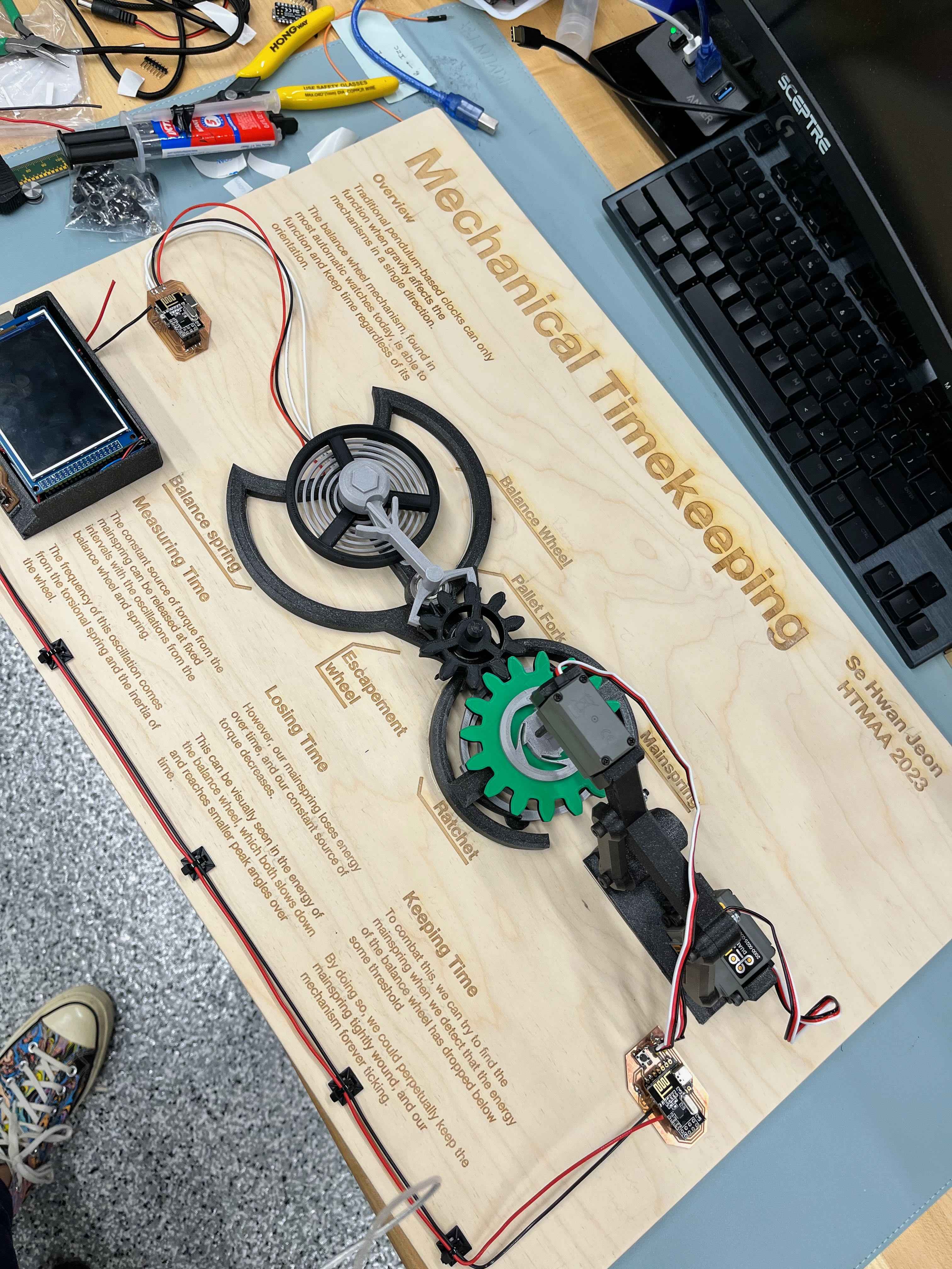
The final product looked like this:
Summary

Progress
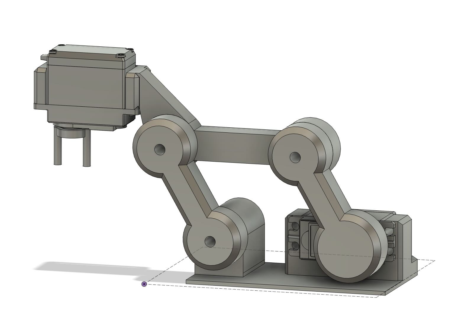
While I feel fairly confident designing controllers and building the components for the robot arm that could wind the clock, I feel much less confident about designing the parts with whatever precision might be necessary for smooth operation. Furthermore, I was planning to 3D print most of the pieces, but I'm unsure if it will be able to print the torsional springs for the driving gear and tourbillon precisely enough.
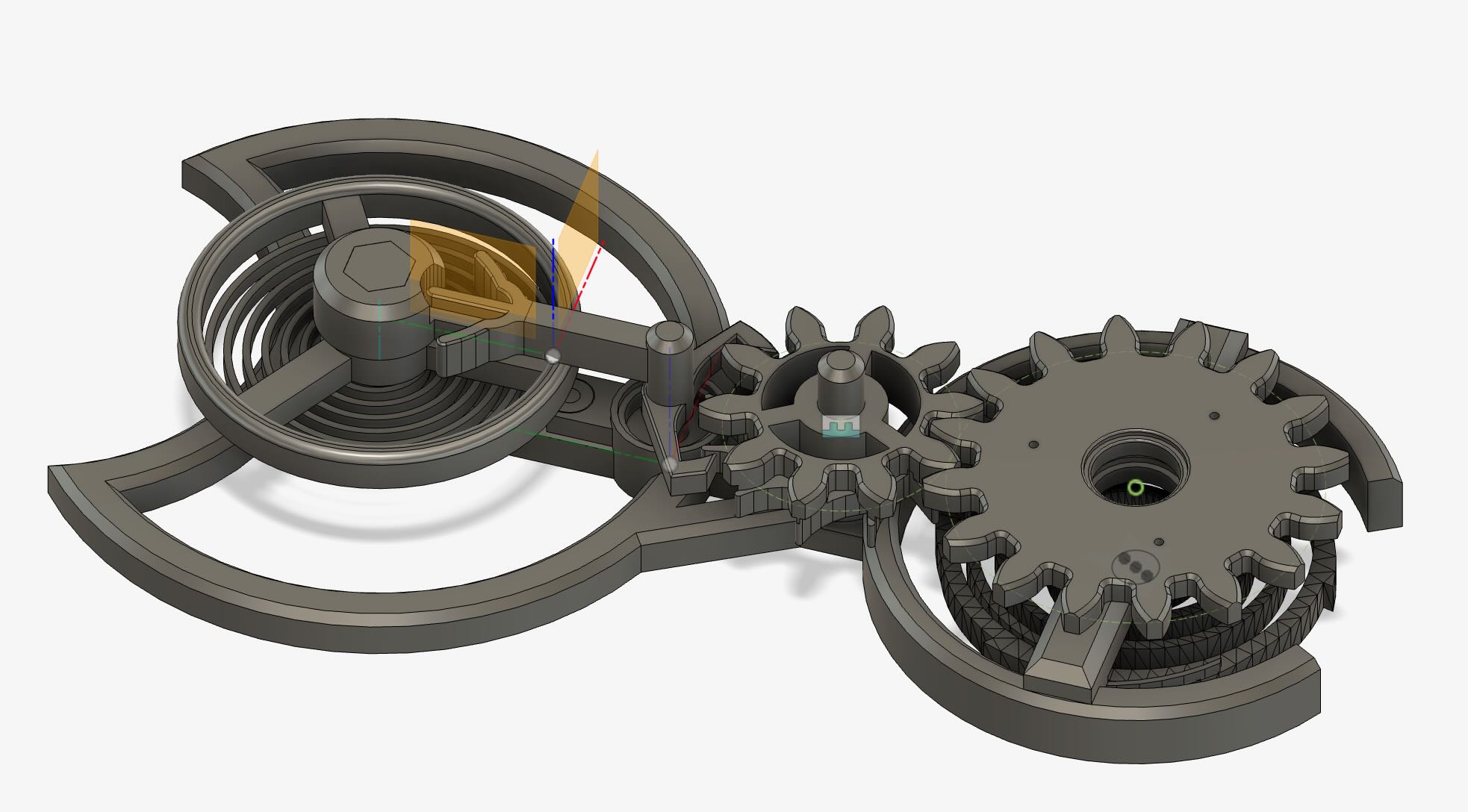
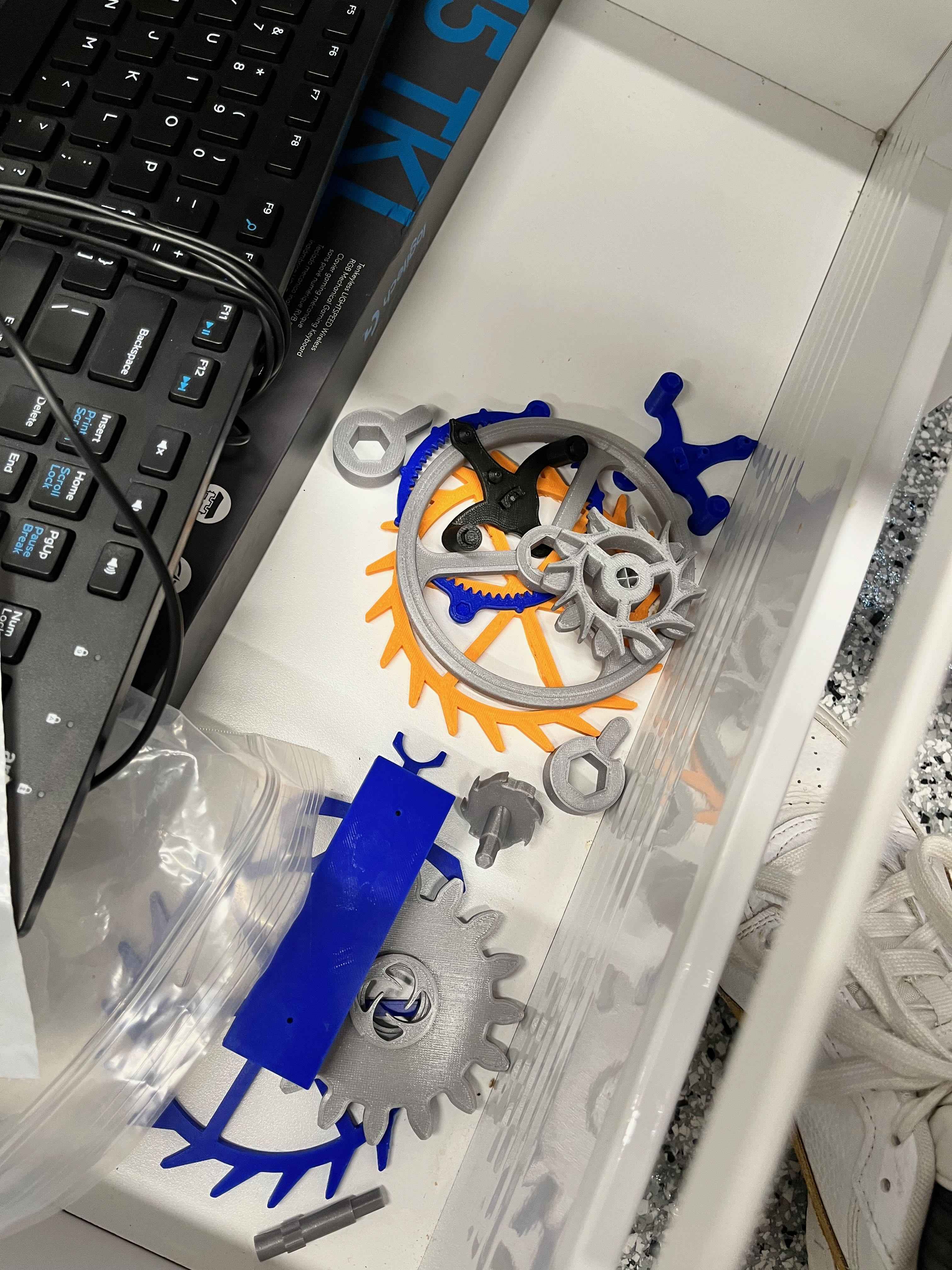
I've prototyped several components for the clock, including the escapement mechanism, shown below.
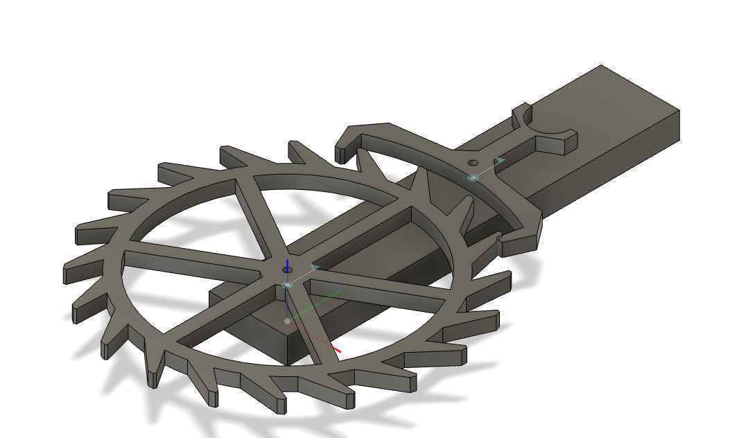
I had to eyeball the pallet fork and do my best to ensure the teeth would align after printing it out.
Given the complexities of the mechanisms involved however, I'm considering downloading and modifying CAD files of the watch components, and modifying them to suit my needs. The precision and complexities of designing the tourbillon in CAD feels a little overwhelming, so I'm leaning towards using publicly available files instead, such as this one. I could modify the parts not only to spread them out on a board, but also, I want to modify the tourbillon flywheel to be able to vary its inertia on demand.
From the 3D printing week, I spent some time modifying a simple tourbillon design I found on Thingiverse. I had to modify some of the hole tolerances and connection pieces for a smoother mechanism, but once that was complete, I printed out the parts on a Prusa 3D printer and used 1.5 mm dowel pins as the axles for the components.
I noticed that the torsional spring began to sag fairly quickly, and the overall scale of the parts were smaller than I would like. My next steps are to scale up the parts, design a variable inertia flywheel in Fusion, and extrude the torsional spring with a larger height. I also need to begin designing the gears that will interface with the driven escapement wheel, and plan out where to fit the sensors necessary for the project. I plan to fit an encoder at the tourbillon shaft connected to a simple display to output the number of ticks or current estimated time.
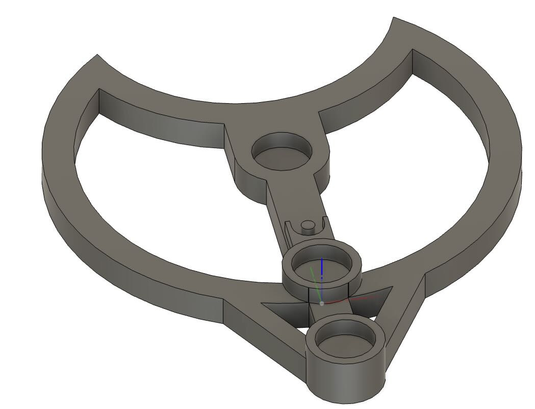
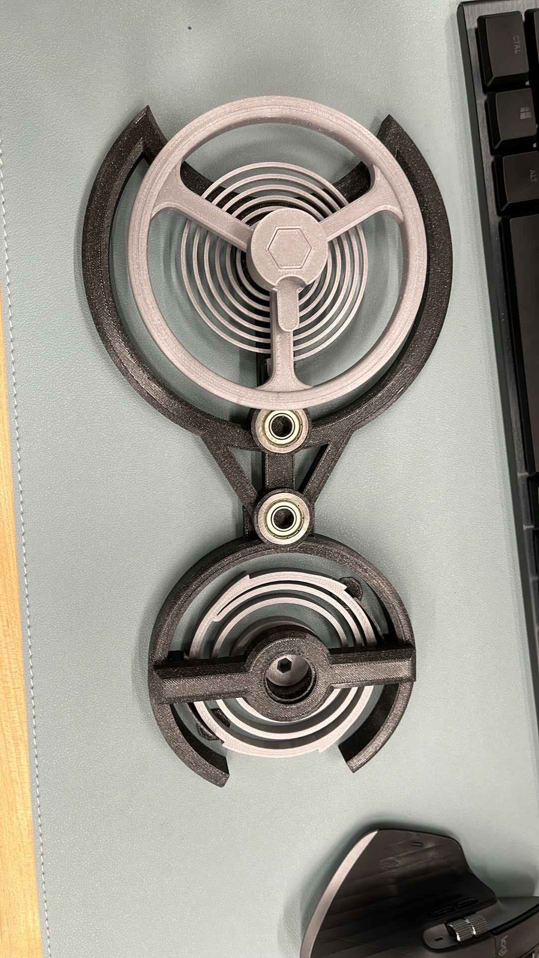
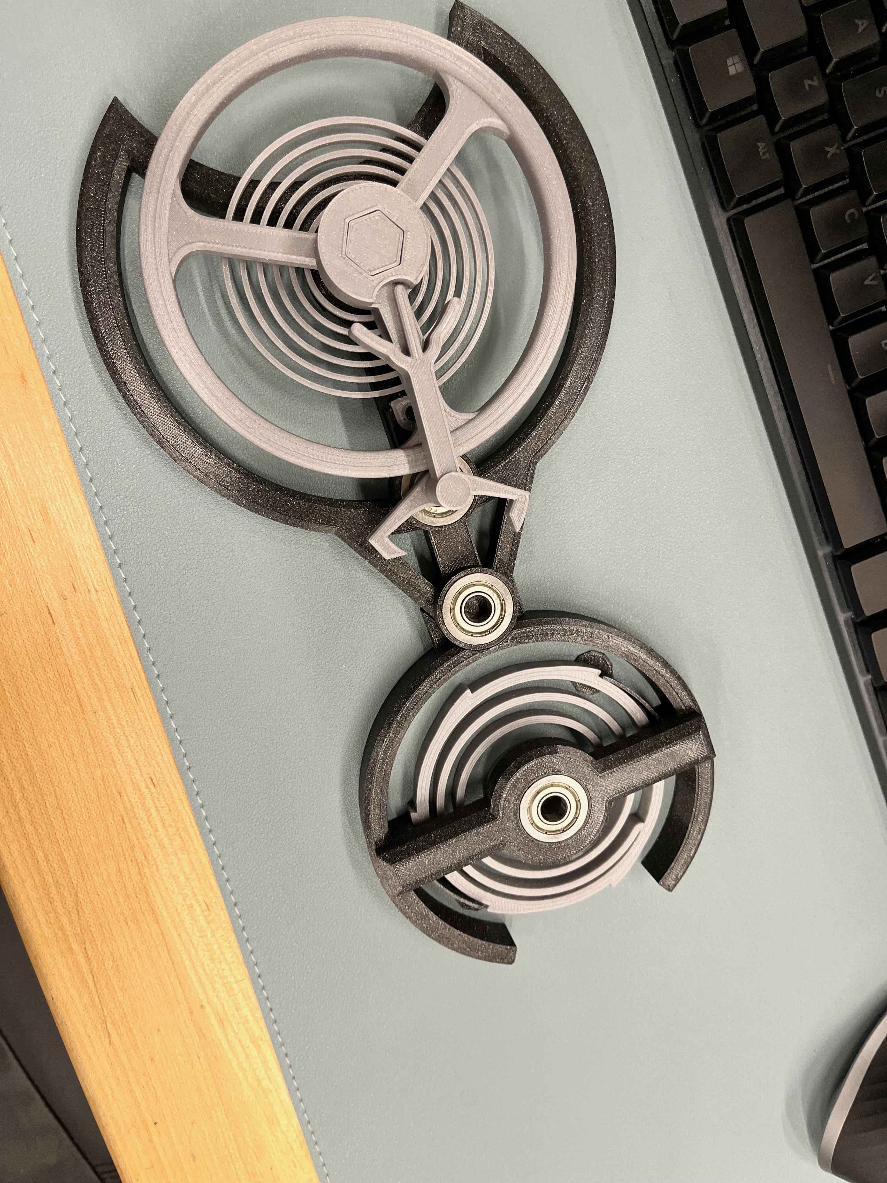
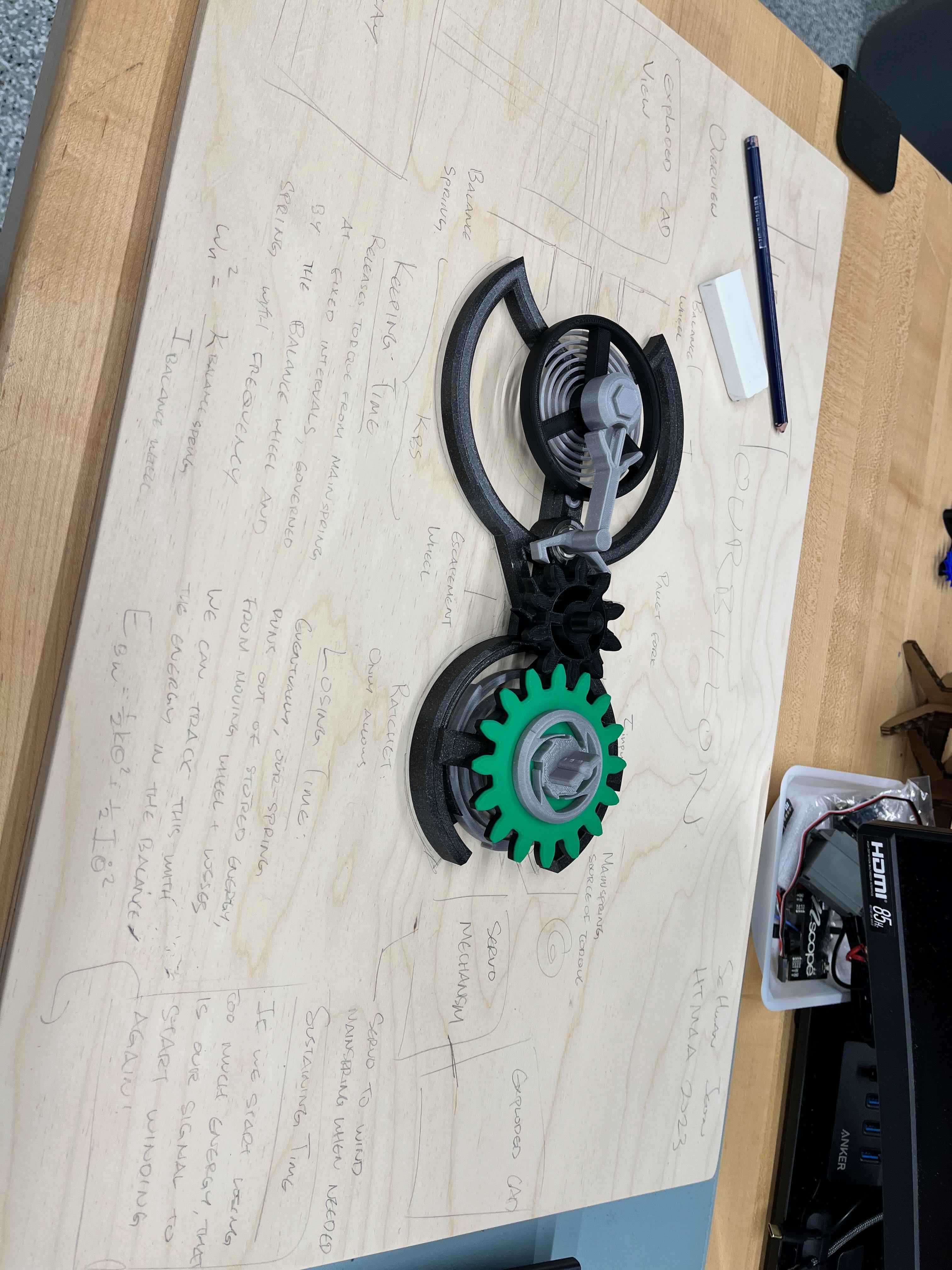
I spent much more time than I expected trying to redesign the housing and balance wheel mechanism for my purposes. The original file had the escapement mechanism rotating on a ring gear, but for the purposes of laying it out on a flat board, I wanted the source of energy to be next to the mechanism. I had to design a new frame to house the spring, and a ratcheting mechanism for the shaft. For my designs, I also tried to give it an Art Deco style as much as I could.
After all the CAD design work was finished, I could begin working on the laser etching for the board. Fusion has a nice sketch feature to place text with any font and size, so I could quickly outline what I wanted to be written.
After exporting the sketch as a DXF, my architect drone friend Diana helped me connect the sketch lines and fill in the outline to ensure the full shapes would be etched.
The biggest challenge with the design was trying to anticipate where the tolerance issues would be. I had to be very careful with dimensioning the shaft and frames so that the gear would mesh just right with each other. Even then, with large enough torques from the spring, it was possible for the gears to catch and skip. I learned to trust the Prusa MK4 and it alone to print at a desired tolerance. Ideally, I would really like to remake just the mechanism with metal in the future. While PLA is great for prototyping, it really serves little purpose for moving mechanisms.
When all the pieces came together though, it was immensely satisfying to assemble the componenets and feel how they all sat together:
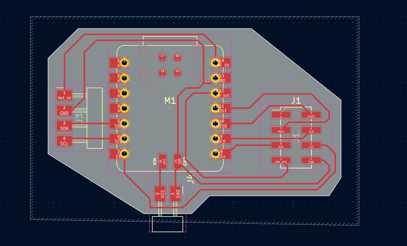
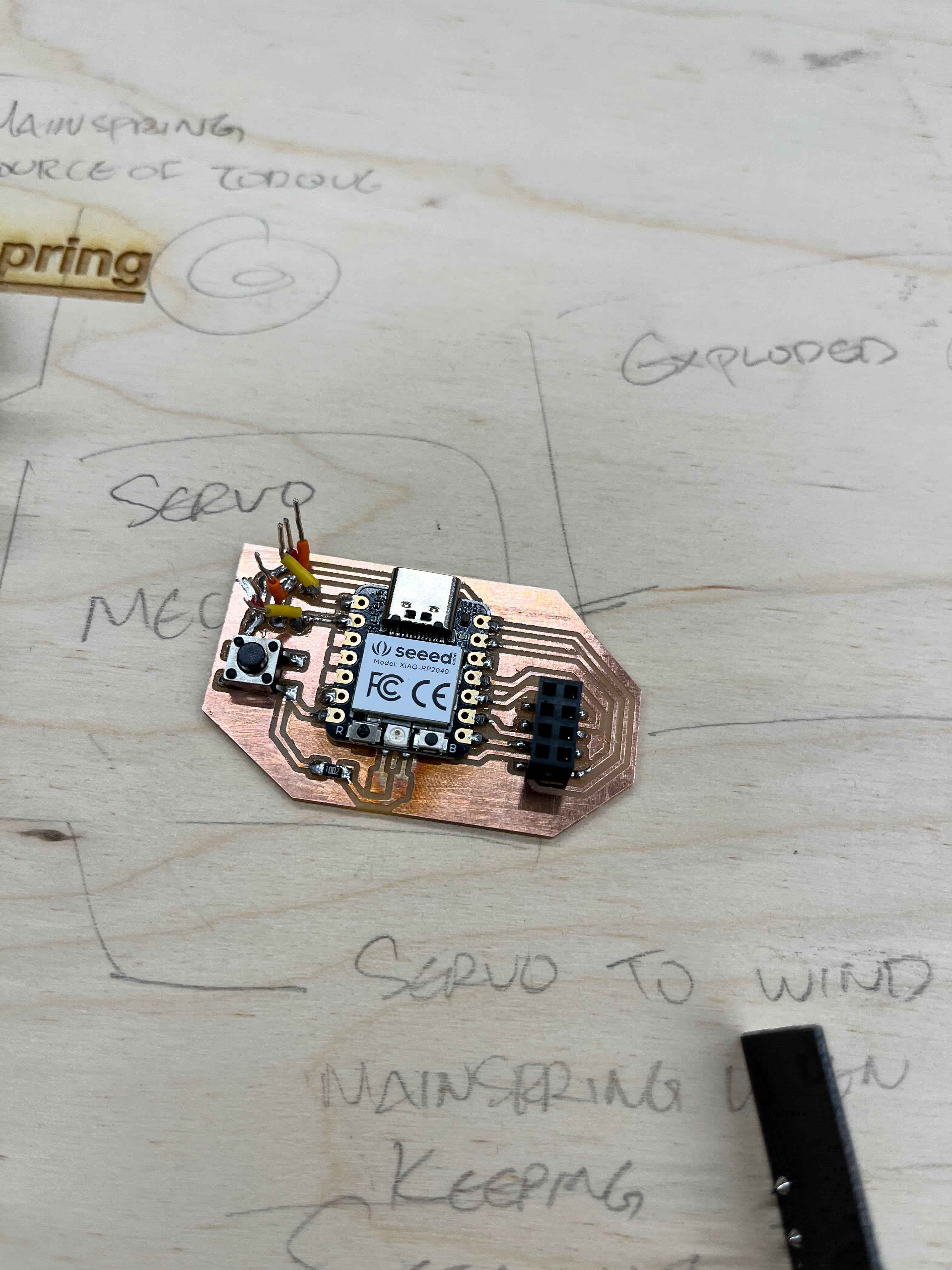
Up next was the electrical design of the components. My project consisted of three main components: the mechanism, the robotic arm, and the encoder/display. With the mechanism complete, I focused on PCB design for the encoder and robotic arm.
Because I didn't want to have criss-crossing wires all over my board, I wanted to try and make each of these modules communicate via radio. I had a few NRF24L01 modules lying around, so I decided to use those. Each PCB needed to connect to the radio module via SPI pins, the arm needed two PWM pins for the servoes, and the encoder needed I2C connections for the magnetic encoder.
I had previously interfaced with these sensors in the weekly assignments, so fortunately I could reuse a good amount of code and design from that work. I also designed a small PCB containing buttons to change the display mode.
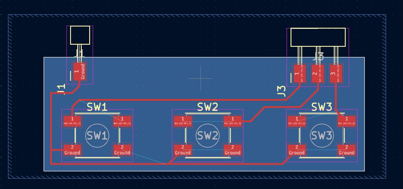
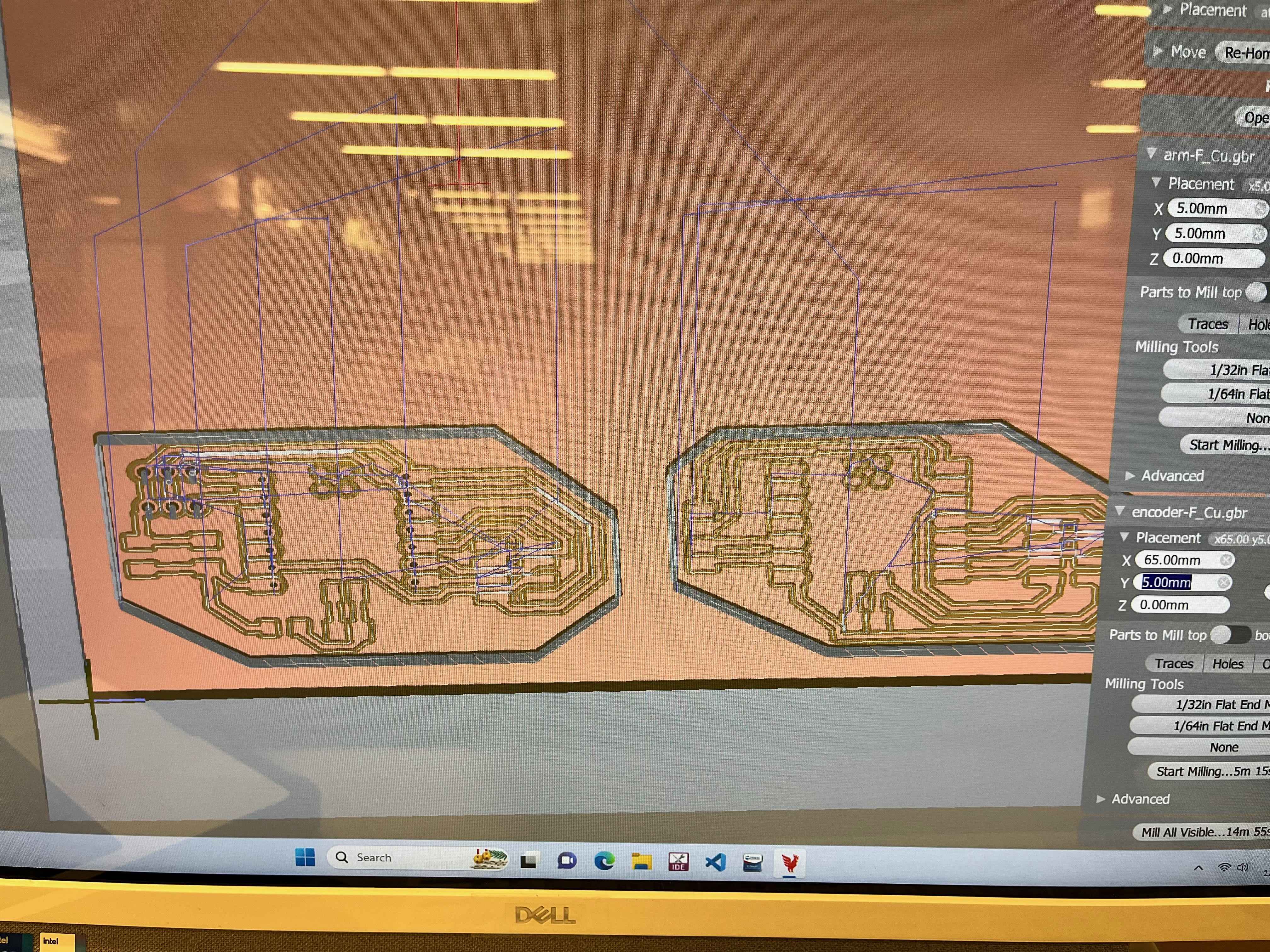
Because of issues with the milling machine in the Architecture shops, I went to the EECS lab to mill my PCBs, which turned out beautifully:

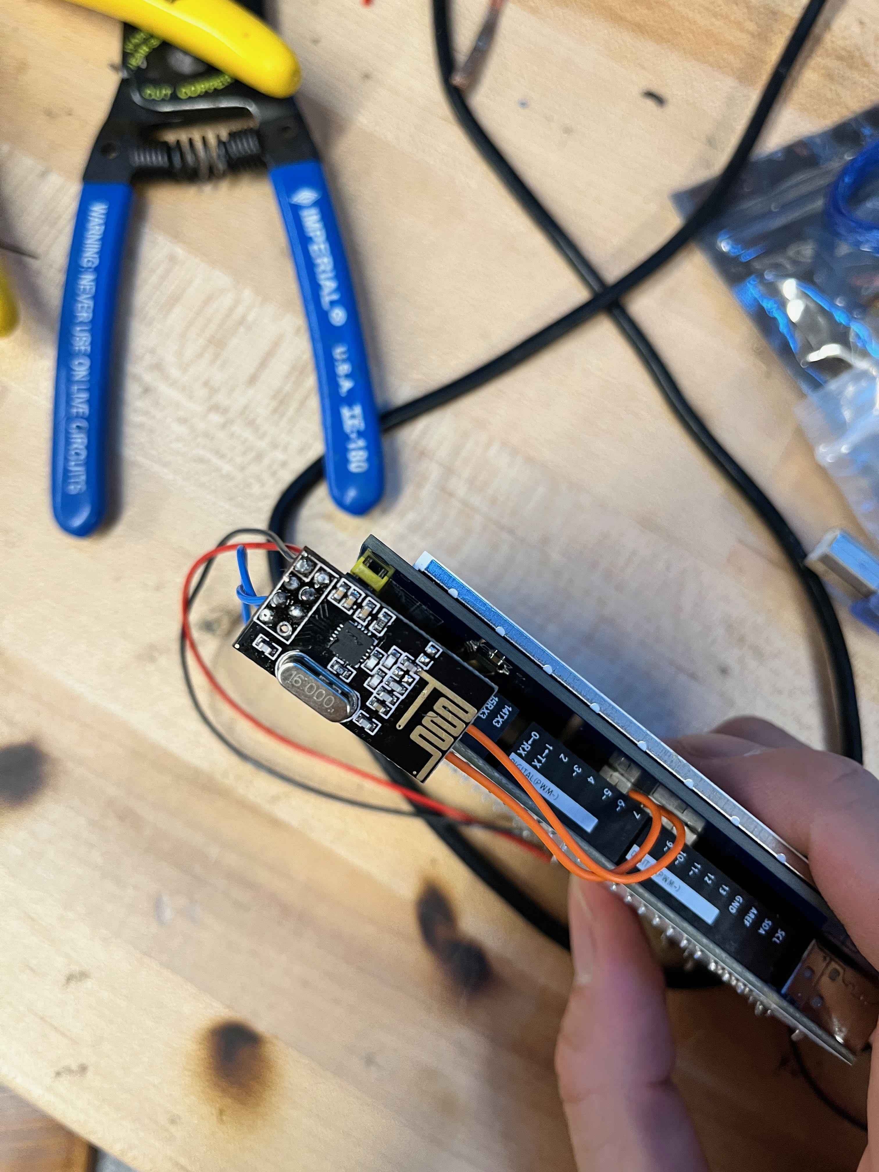
I learned a lot from designing, but I would argue even more from integrating. I had to get extremely creative in improvising and quickly performing "surgery" on PCBs I had made. With time constraints, I was extremely reluctant to reprint anything, and ended up relying on a lot of hacks to get my PCBs to connect correctly. One of the most egregious examples is shown below:
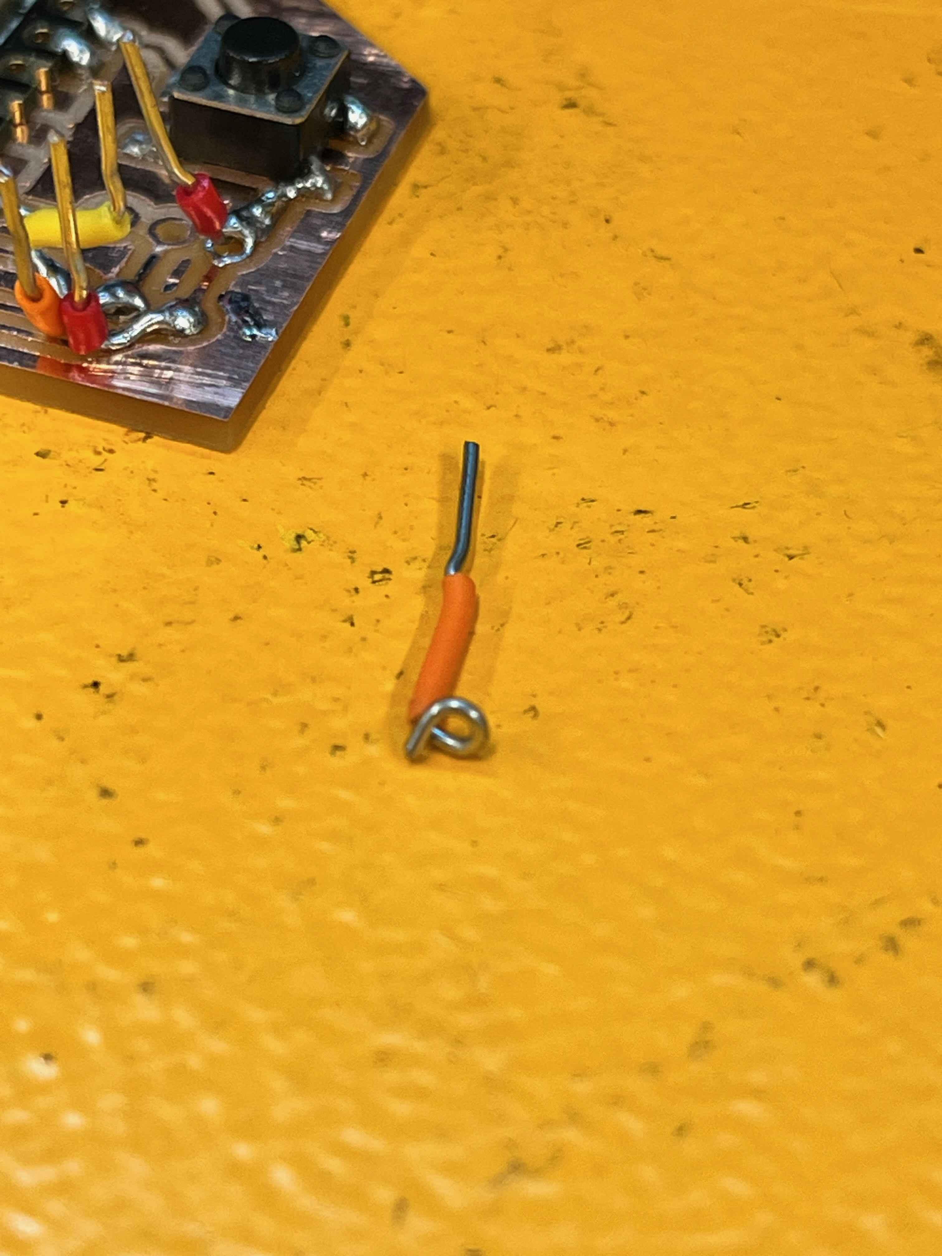
I had to cross the wires for the servo PCB, because the socket headers from the servo were in a different order than I had realized on my board. However, I was fairly happy with the final product - from continuity tests, all my connections were solid, and the radio module sat very nicely on top of my board, like a miniature shield.

The most frustrating part of the project by far was using the TFT LCD display. Not only was it completely incompatible with the Xiao board, it also required some byzantine libraries and code for processing. I spent far too long trying to interface it with the RP2040, before eventually just using one of the Arduino MEGA 2560s I had from TAing 2.007.
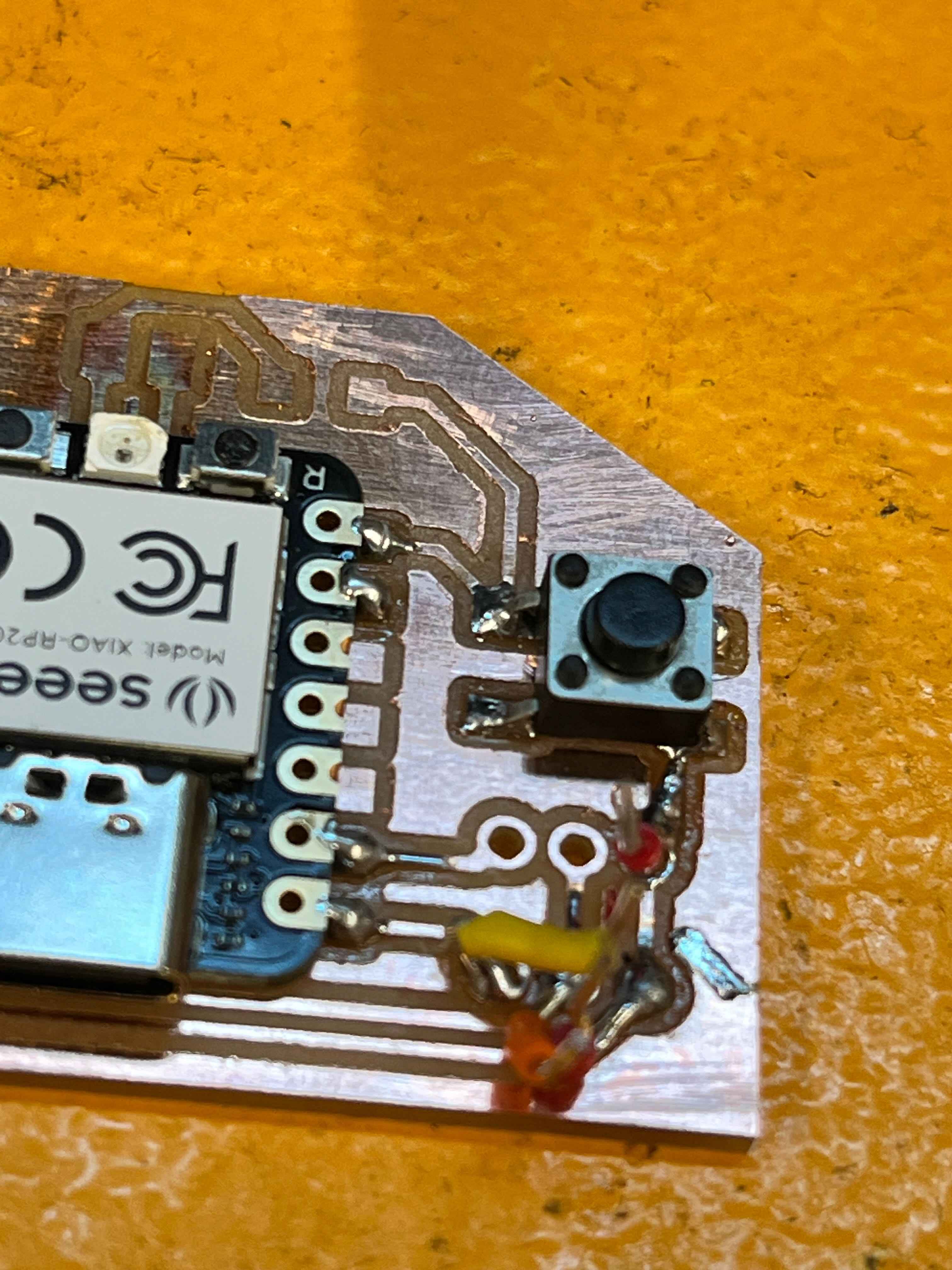
On the board itself, I had to solder my connections to the back of the board to avoid interference with the display. I also had to solder multiple power and ground connections to the same pin, which resulted in some extremely suspicious connections:
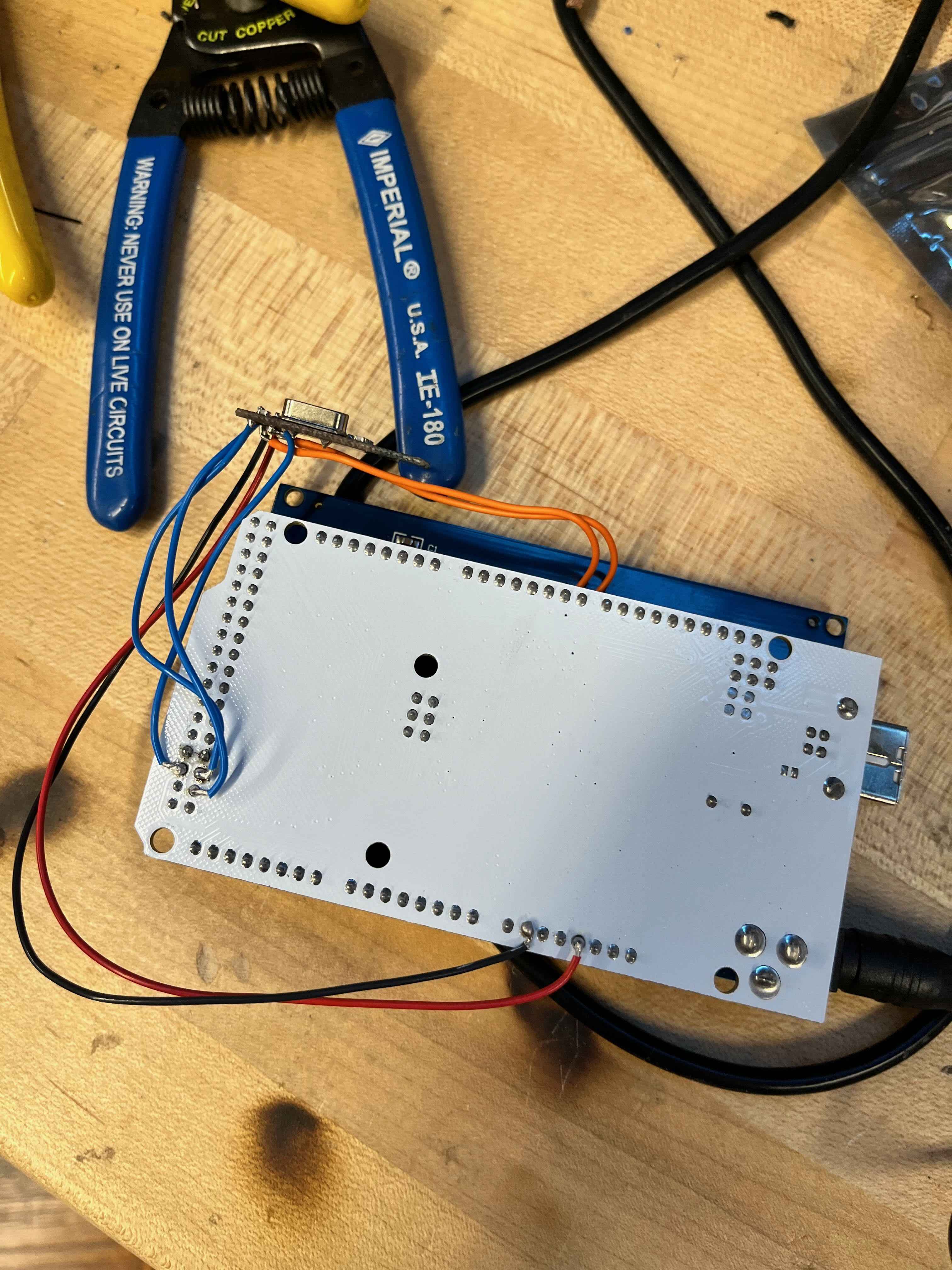

Incredibly, all my connections seemed solid, and continuity and voltage tests from the multimeter confirmed that I was able to send power and signals to the pins I specified.
With all the electronics coming together, it was time to assemble, and I laid out all my components on my board for spacing. I had to iterate a few times between my laser etching sketch and the actual components, but I was able to get a fairly good fit.
With the positions finalized, I went to the EECS lab again to laser cut my board, which turned out much better than I had hoped:

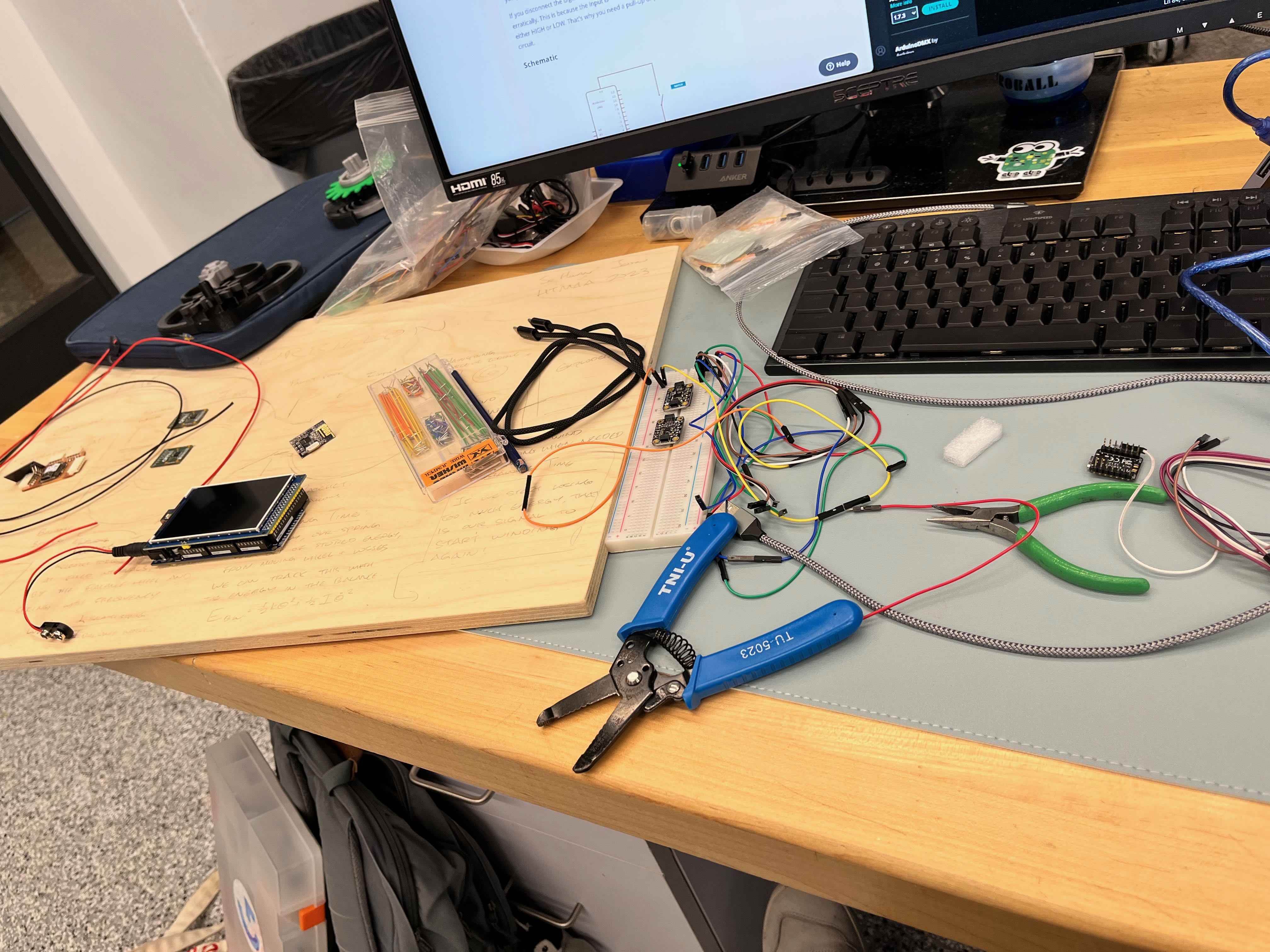
Finally, I could begin my final assembly. I had all my electronics and wiring ready, parts printed, and board cut. I planned to secure most of the components with double-sided tape and epoxy, then solder things afterwards. Before I began mounting things however, I tested my electronics with breadboards to ensure their operation:
After confirming all my electronics were functional, I began my final assembly:

As always, there were several critical mistakes I made near the end that killed the functionality of my components. Firstly, running on far too much coffee and far too little sleep, I accidentally connected the display to two different USB sources of power, and immediately fried its connections. It was no longer able to render anything on screen except white LEDs. Secondly, I wanted to test the functionality of the auto-winding mechanism, but ran out of time to thoroughly test and debug the kinematics. Furthermore, because of the brittleness and tendency of the balance wheel to get jammed while unwinding, I was afraid the powerful servos might snap some part of the 3D printed design, and didn't continue testing. However, my magnetic encoder readings worked perfectly, and I only wish I could have projected them to a screen to demonstrate the timekeeping performance of the designed parts.
I was happy that the main mechanism was still able to function. If I hadn't fried my display at the last minute, I'm confident I would have been able to integrate the rest of the components. My biggest enemy was time, and I wish I had begun debugging and assembling earlier and in a more coherent state.
Reflection
I'm very happy with the final product, and I think it's a great proof of concept for the idea. I'm also satisfied with the design of the mechanism, and I think it's a great example of how to design a mechanical system with a lot of moving parts. I'm also happy with the electronics design, and I think it's a great example of how to design a PCB with multiple components and sensors.
One major regret is that I wish I designed something a little more complex electrically. While I learned a ton about mechanical design, I wish I had the chance to use actual motors and power electronics, instead of these breakout boards and simple connections. Furthermore, I realized that I underesimtated how long certain tasks could take, and needed to better manage my projects and limit how much I helped other people.
Lastly, I feel much more confident in tackling building in general, and really felt like I learned a lot from the course by just doing, trying, and failing. I would love to try and continue making additional mechanisms like this without the time pressure of a final exam, and carefully machine these parts out of metal instead of 3D printing them. It would be amazing to do a series of these mechanisms, from simple gear trains to more complex transmissions and differentials.