Week 5
Electronics Design.
Engineering Files
Microcontroller Operation
To test the operation of the microcontroller, I grabbed a digital multimeter we had around lab and measured the current and voltages of various pins on my Xiao breadboard from last week.
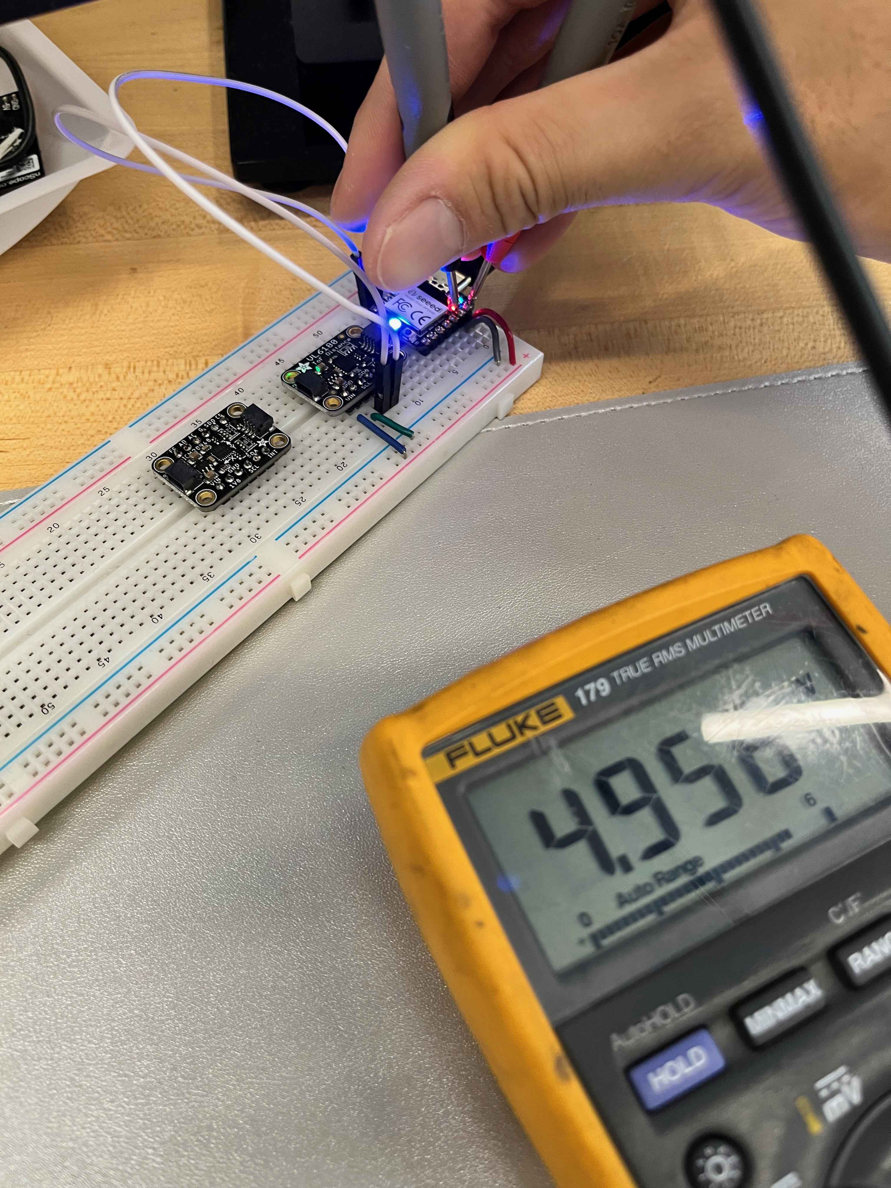
As expected, I read out the 3.3V and 5V from the power pins, and the 0V from the ground pins. I was also able to see the voltage drop across the ToF sensor as it was activated.
Development Board Design
I decided to use KiCAD to design my development board and PCBs in the future. Whild I had been using Fusion 360 for CAD, some people in my lab recommended KiCAD over Eagle, if I couldn't use Altium.
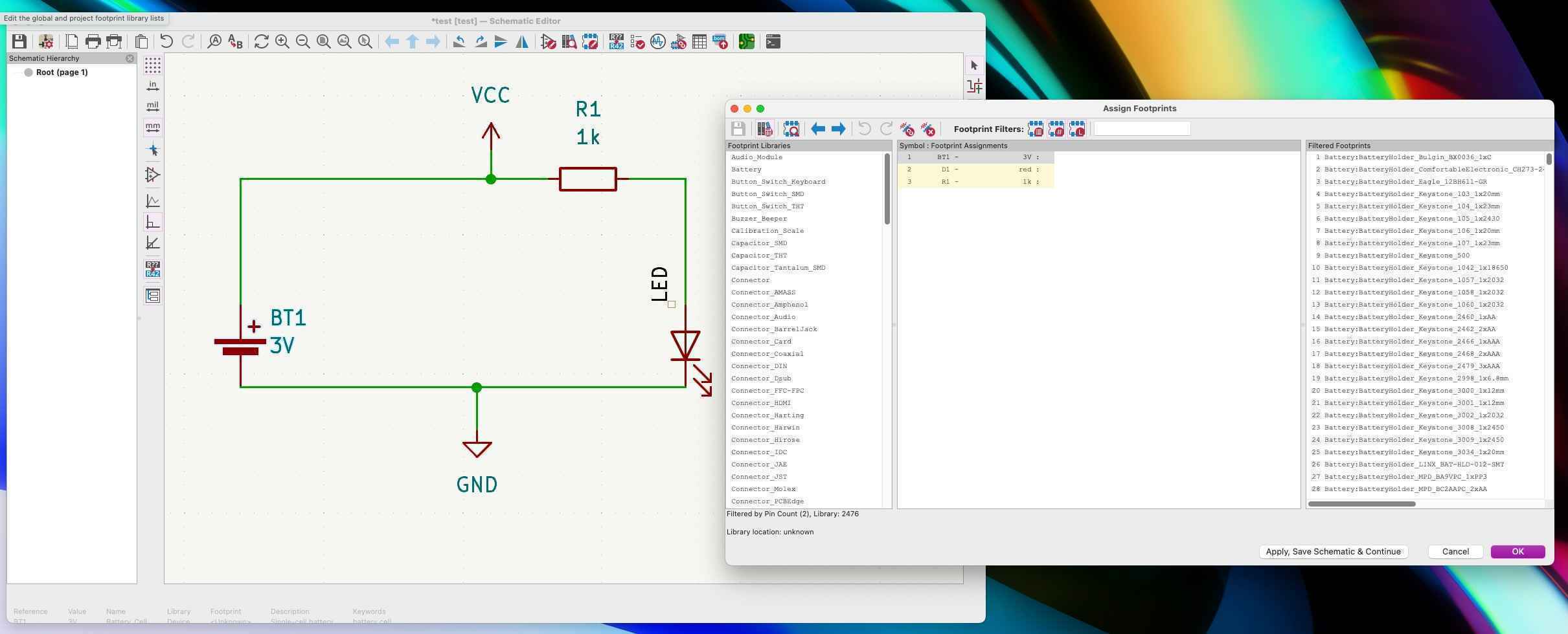
I began by downloading KiCAD, and following the tutorial on their website to design a simple development board for an LED connected to a power source. I began with the schematic layout of the PCB, which looks like this. One thing I was unsure about is how exactly the "footprints" are chosen for the parts. There are an overwhelming number of parts to choose from, and I have no idea how someone manages all the tradeoffs.
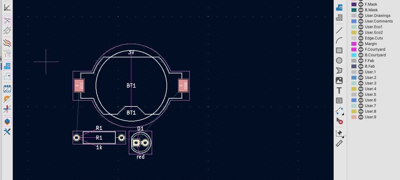
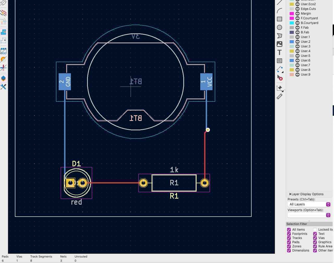
After the schematic was designed, I laid out the parts on the PCB and connected them with traces. While the routing was trivial for such a simple board, it was much more challenging for the Xiao breakout extension I tried later. The KiCAD tools were all fairly intuitive - by using the Electronic Rules Checker and Design Rules Checker tools provided, it was straightforward to make sure that the designs were functional.
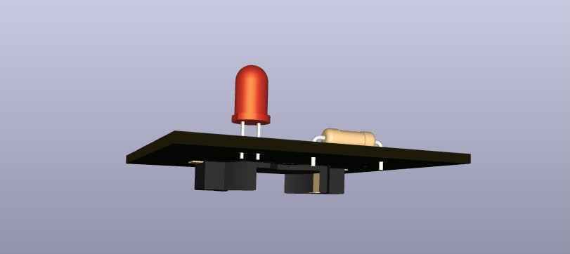
With the PCB design finished, KiCAD has a feature to visualize the final board in 3D, which is shown below for the LED.
For the rest of this week's assignment, I wanted to design a breakout board for the Xiao. I'm still planning out all the components, sensors, and signal flow I need for my final project, so for now, I wanted to gain experience by simply designing breakouts and connection pins for the different communication protocols available on the Xiao.
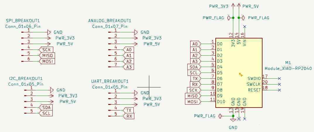
As with the LED, I started with the schematics, and setup 4 different breakouts for the Xiao: I2C, SPI, UART, and GPIO (analog). I put "no connection" pins for all the pins associated with the reset, boot, and USBC connections, and then defined my power flow out from the 3.3V and 5V pins, along with my ground.
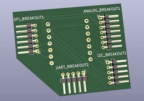
As with the LED, I then laid out the parts on the PCB and connected them with traces. This was much more challenging, as each of the breakout pins needed to be connected to the power and ground pins from the Xiao, and avoiding overlap was challenging. However, with the two layers of the PCB, I was able to route all the connections without any overlap.
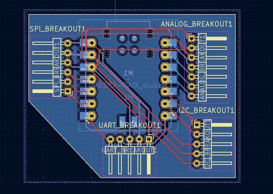
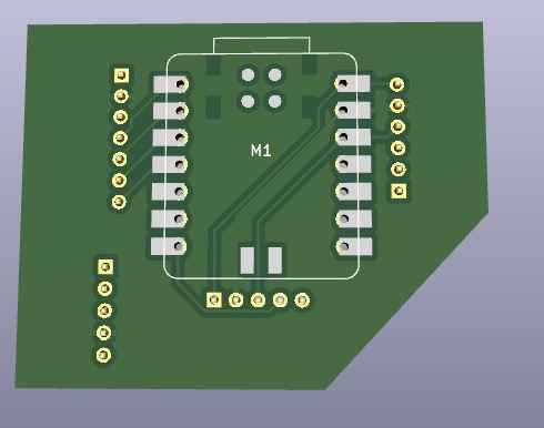
On revisiting the board, I realized that I could probably done the tracing in a cleaner way by putting the SPI and analog traces on the bottom layer, and the other two on the top layer. Regardless, my design passed all electrical and design checks, and I visualized the PCB in 3D as before.
I still need to layout exactly which components I need for my final project (encoders, displays, motors, etc.), but once I do, I feel confident that I could design the PCB I need for them.