Week 6
Electronics Production.
Engineering Files
- N/A
PCB Production Process Characterization
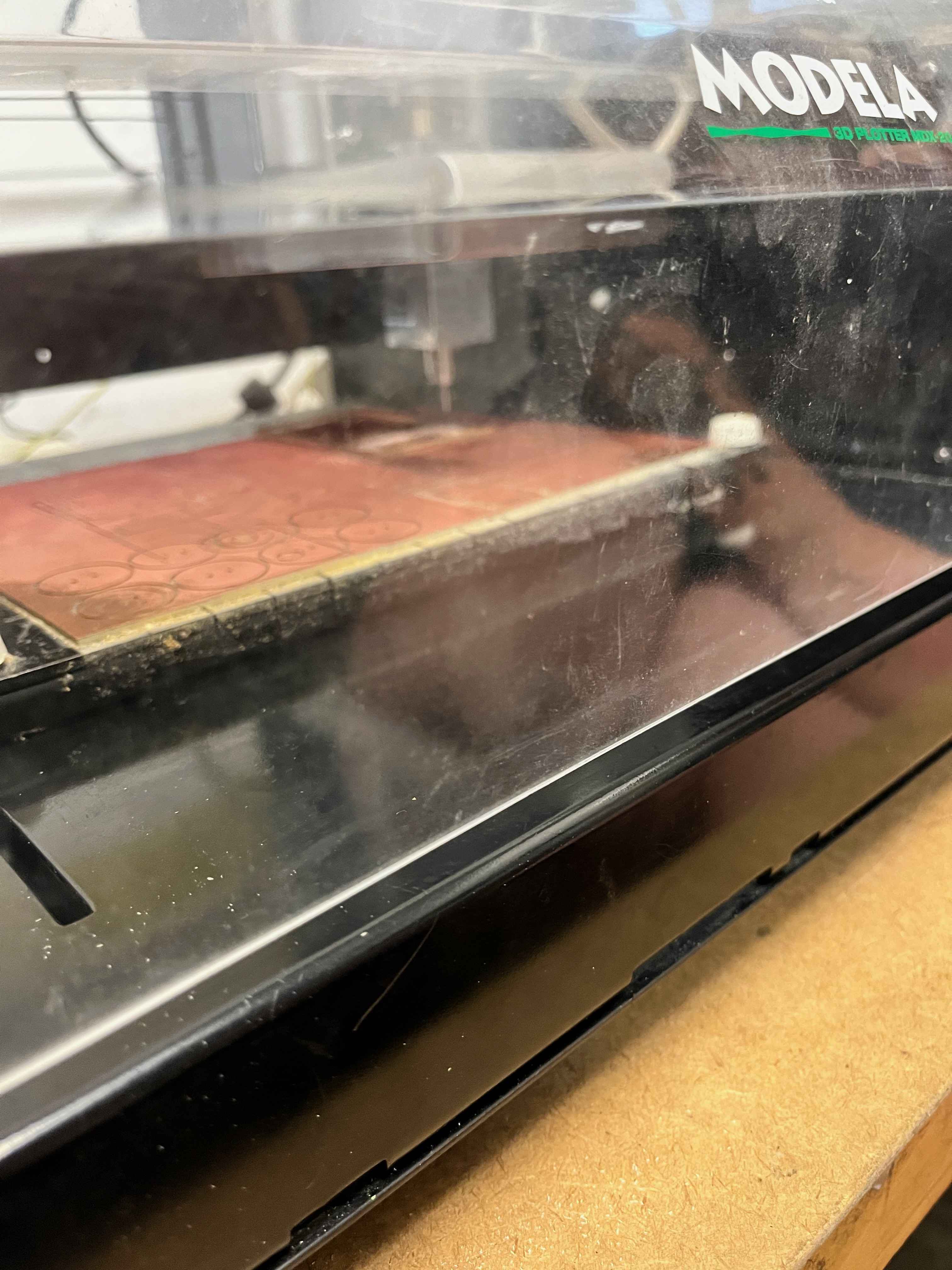
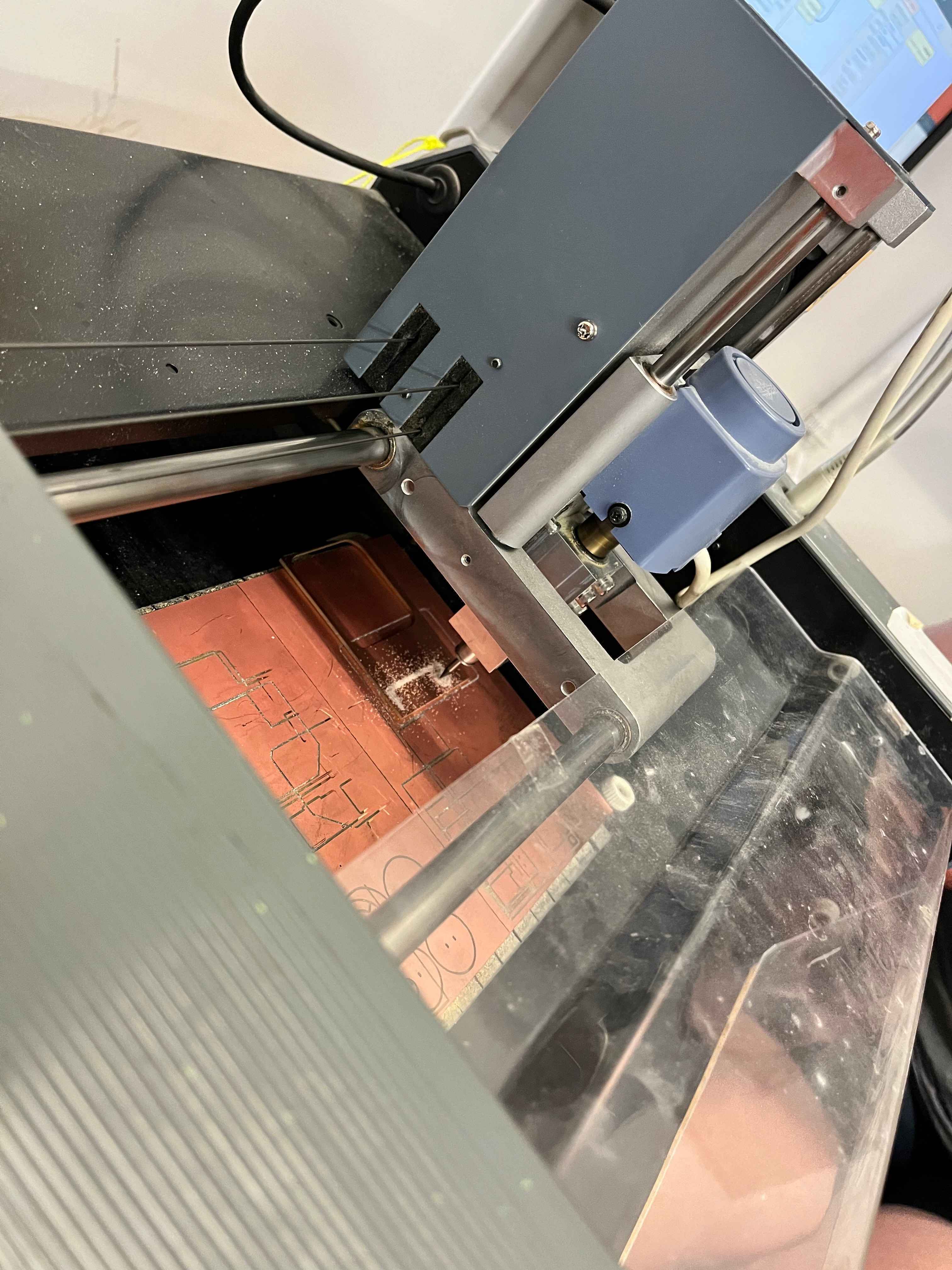
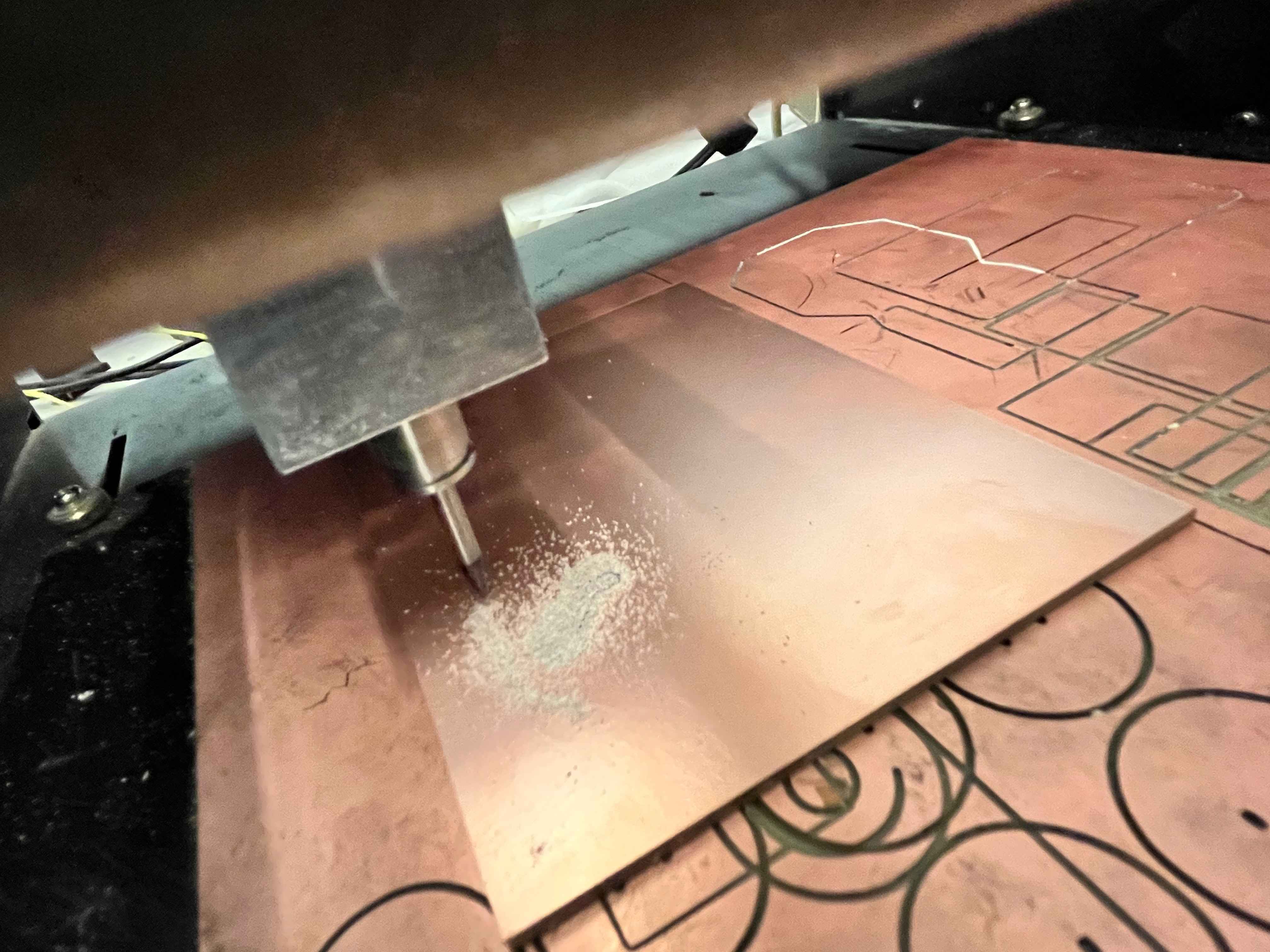
To characterize the process of PCB production, we used the Modela milling machines, pictured here:
We wanted to evaluate what the tolerances for the machine were to govern our design constraints for the PCB. The board we wanted to mill for this purpose was taken from the HTMAA site, and looked like this:
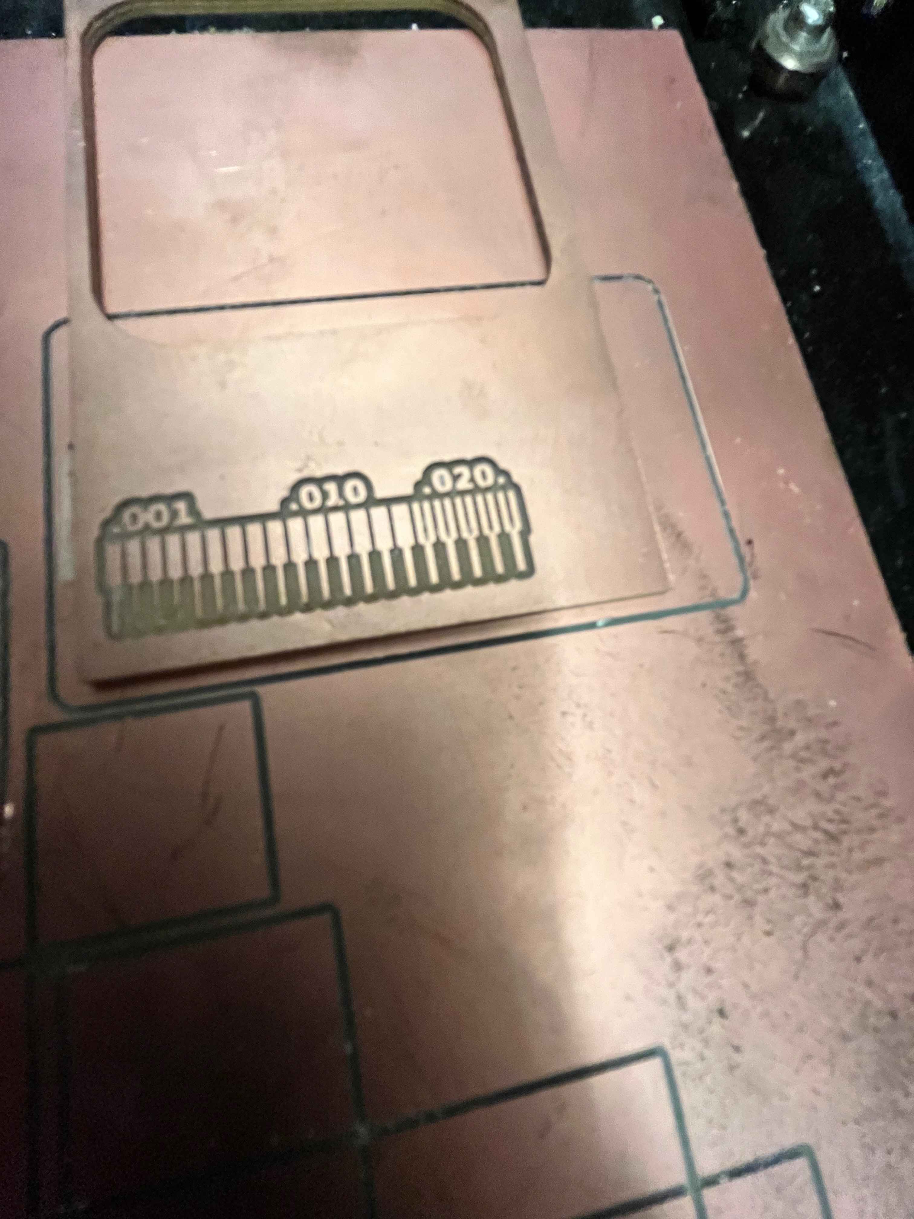
With traces thinner than around 0.01 inches, the Modela machine could no longer produce clean traces, so I set my PCB trace thickness constraints to be at 0.01 inches. Knowing this, I revisited the board I designed last week for production.
PCB Board Production
I designed my original PCB as a simple breakout of the Xiao microcontroller. Last week, I had asked the hardware people in lab about communication protocol, and learned about the different types (I2C, UART, SPI, etc.) available on the Xiao. For the breakout, I wanted to group the pins for each communication protocol in a convenient way, and I designed my PCB in two layers accordingly:
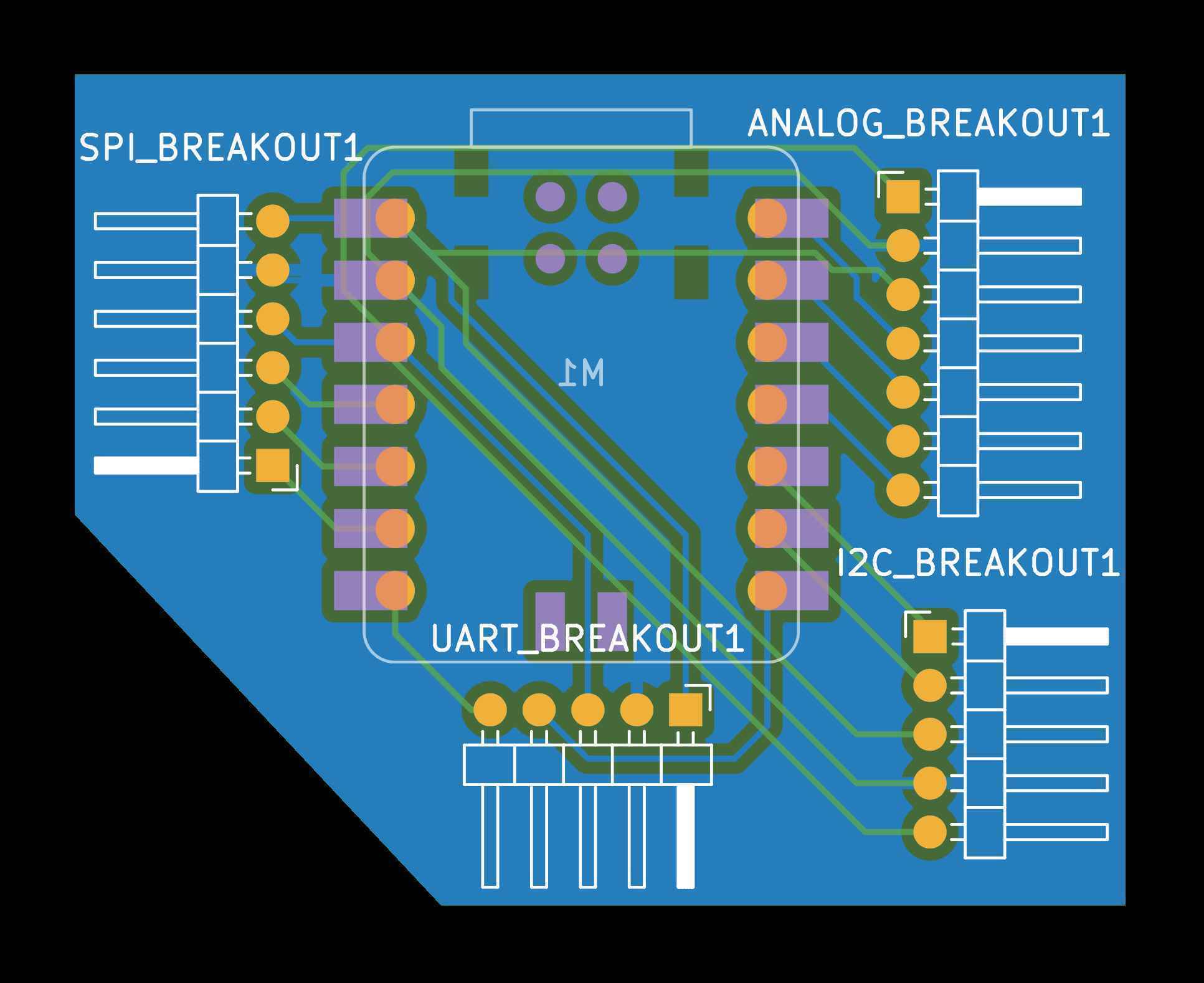
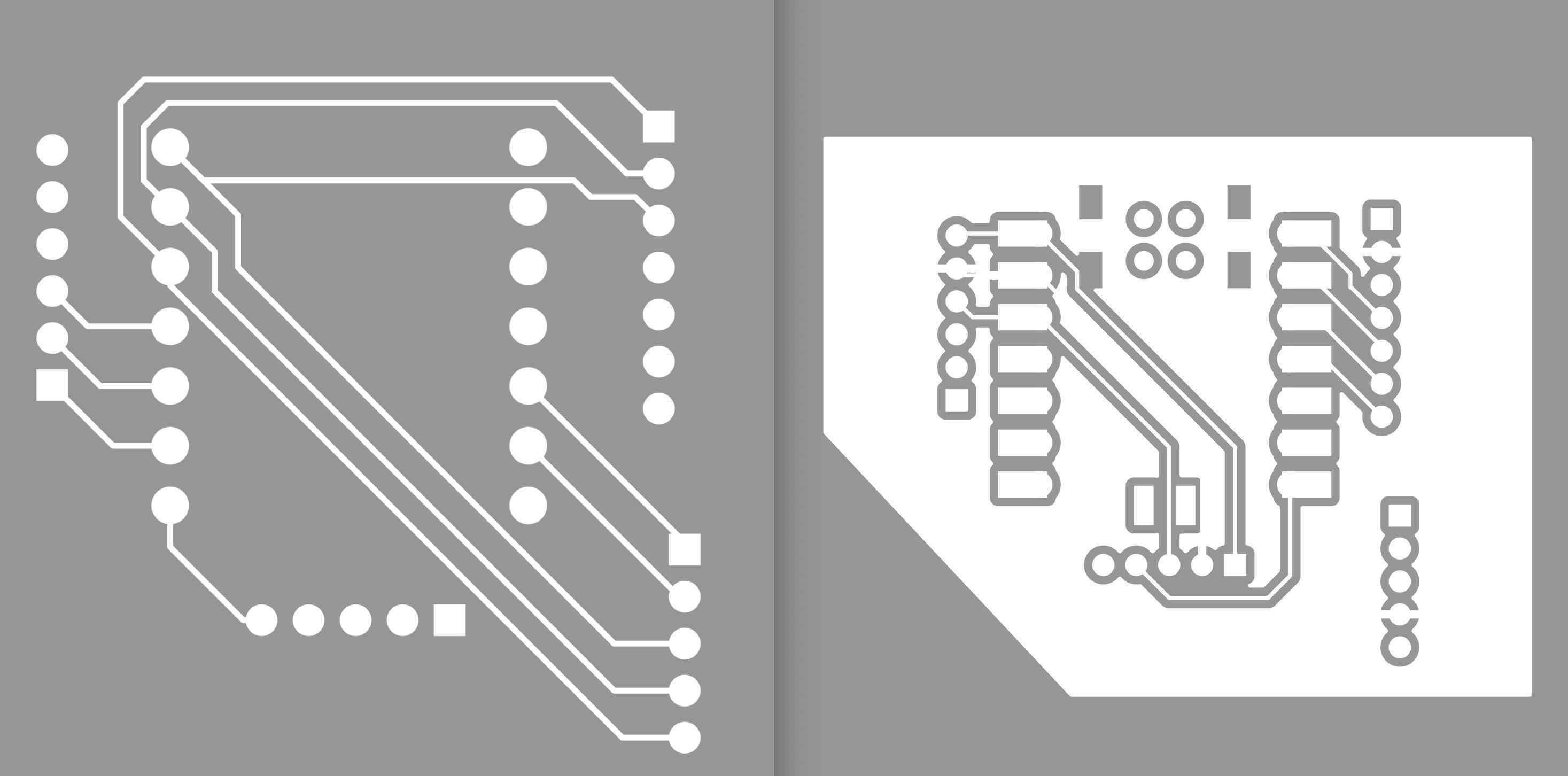
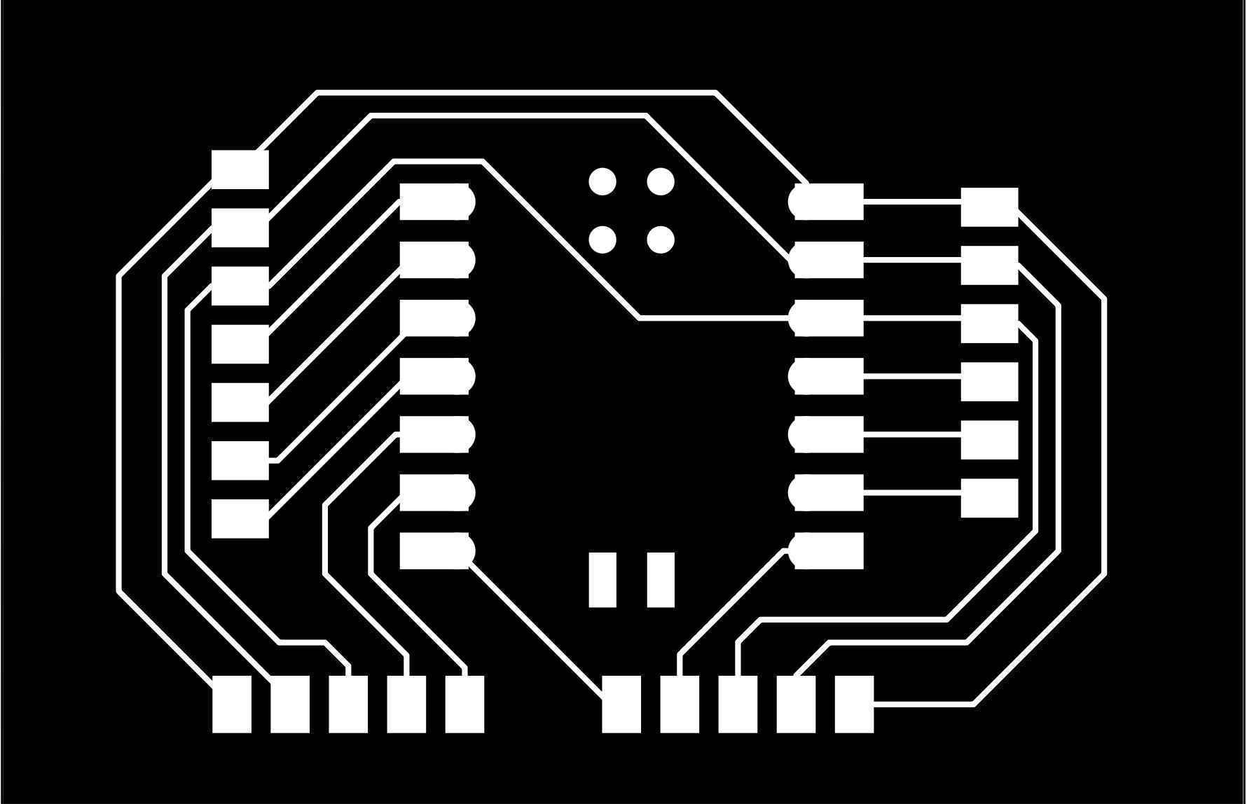
Unfortunately, I learned about some complexities with manually milling a two-sided PCB, like aligning the PCB and re-zeroing the origin exactly for the traces and througholes to line up. Ultimately, I didn't want to deal with the hassle, so I redesigned my board to be one-sided, which ended up looking cleaner than my original design anyways:
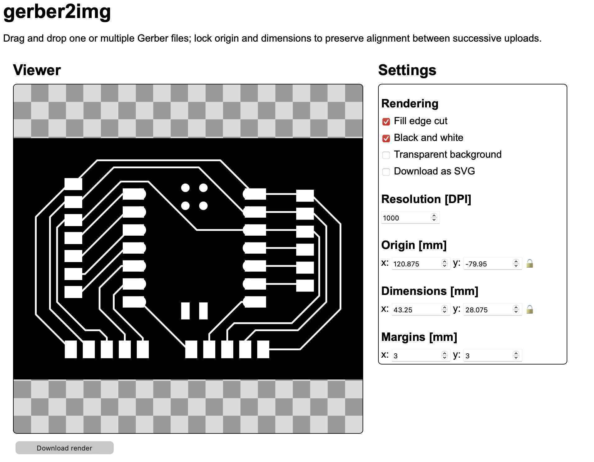
I then had to convert my gerber files into PNGs for milling, and I used Quentin's gerber2img tool:
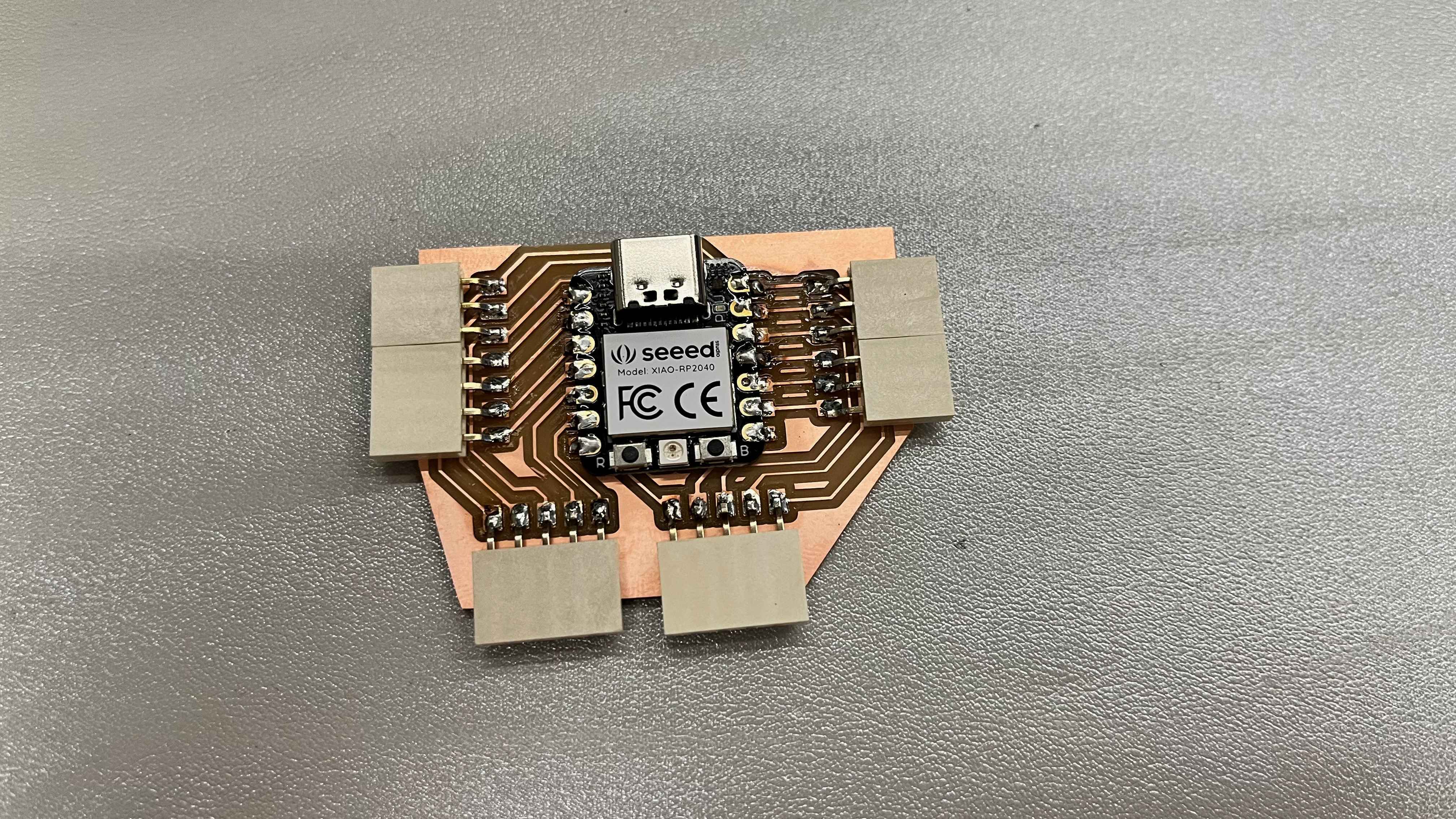
Finally, I sent my files to the Modela mill, and cut out all my traces and edge cuts from my board. The traces took a surprisingly long (~30 minutes) to fully cut.
I spent some more time soldering the pin sockets and the Xiao to my milled PCB. I did a terrible job soldering the microcontroller, but I became more comfortable soldering the sockets. After finishing, I plugged in the Xiao to a USB-C connection, and confirmed that it could power up.
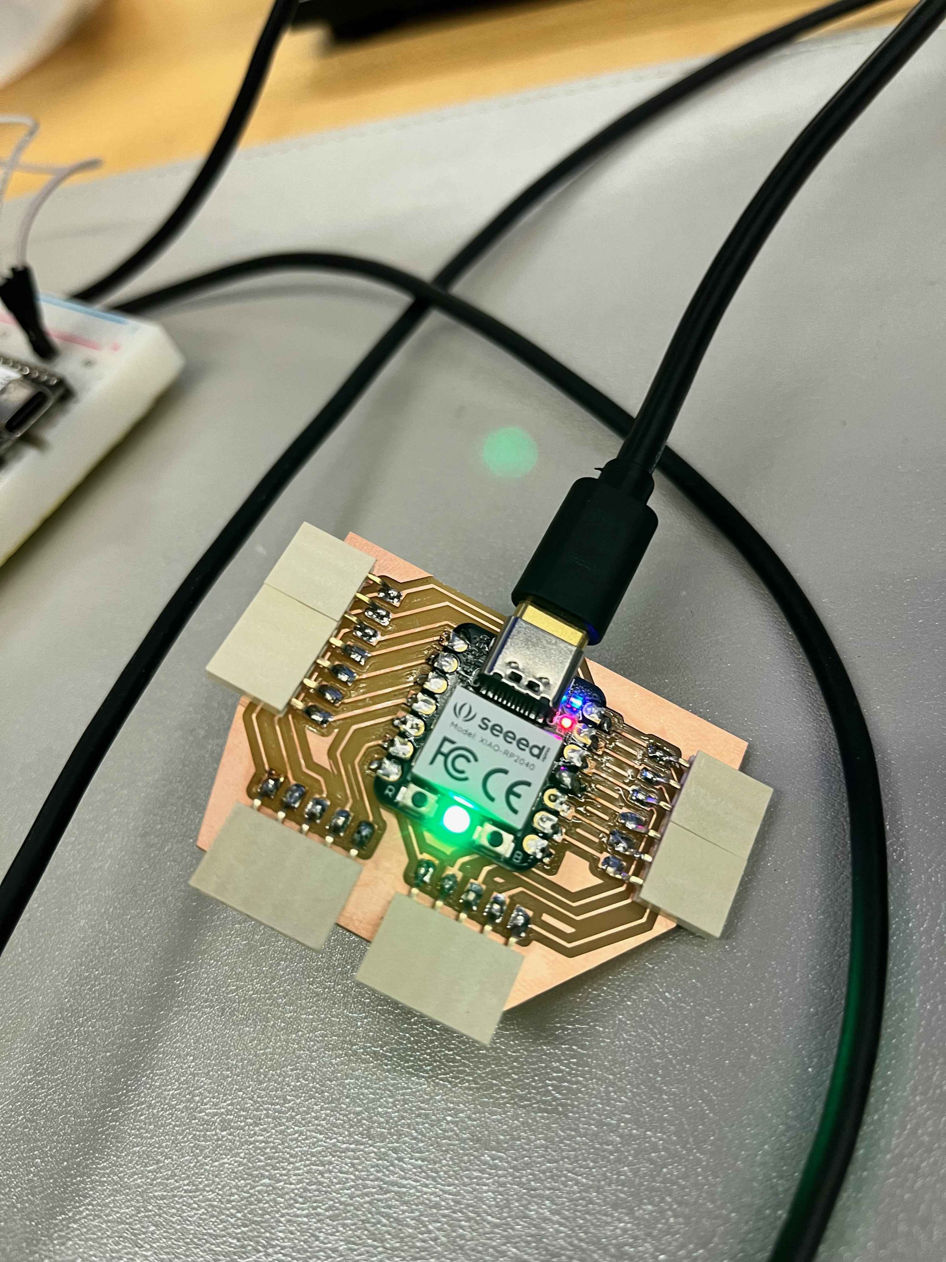
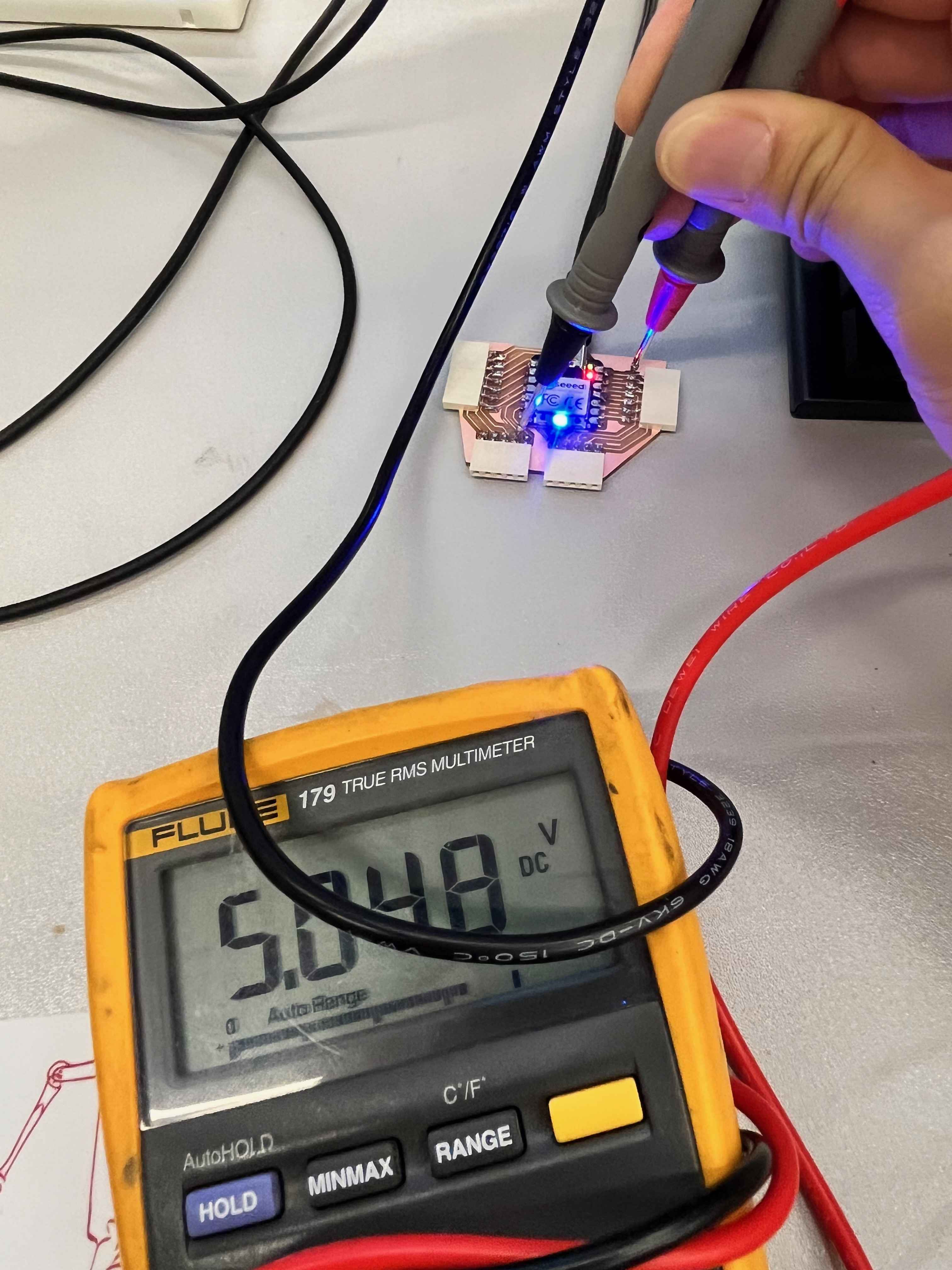
Lastly, I wanted to check that all my connections and traces for the breakout board were functioning as expected. I grabbed a multimeter from lab and checked that all the power pins and traces were at the expected voltages. While most of the showed the expected 5.0/3.3/1.7/0.0 V, my power pins for the SPI and analog breakout sockets showed zero voltage. It's possible they were shorted or had the traced broken somehow.