Final Project
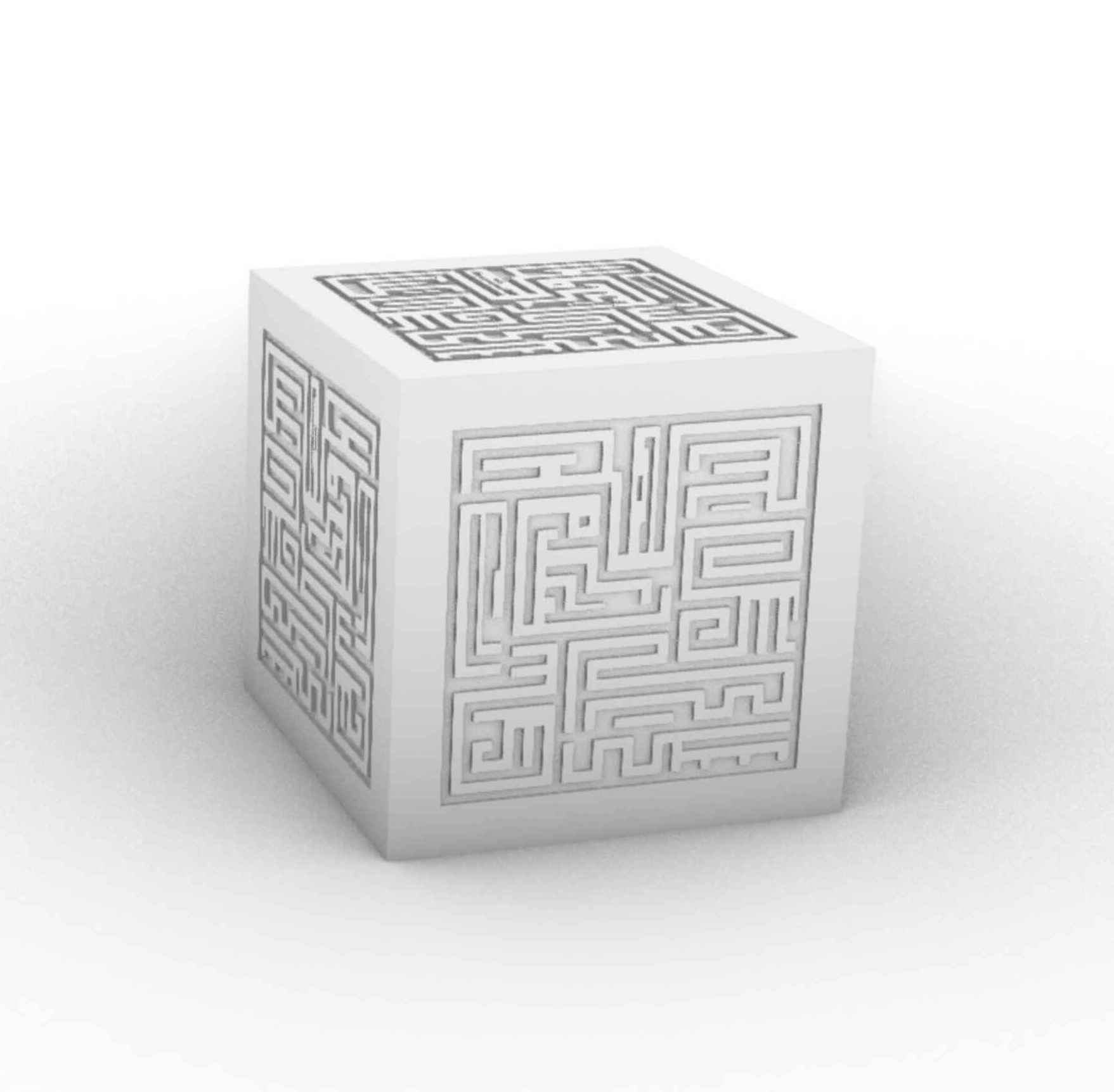
My goal for how to make is to reproduce these blocks from Castle in the Sky:
Inspirations
The idea came about from a bunch of sources. I love clean designs with beautiful mechanisms. When I first saw Miana's self replicating robots during a CBA lab meeting, the idea of simple geometric cells with controllable embeded circuits really got my attention, and of course the self replication is really captivating.
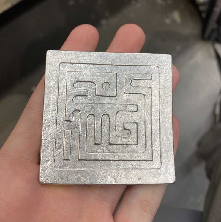
As a side project to learn more about cnc milling, I had planned to mill out the design of one of these cubes out of aluminum. Seperately, during freshman year, I took a seminar on making things and made a brushless motor. At the same time, I have taken a bunch of classes on basic circuits building and analysis, but I don't feel like I have much practical design knowledge or experience. All of these came together when I was brainstorming for final projects and I thought, what if I could make the cubes, add a linear version of the magnetic actuators from the brushless motor, and control everything using embeded systems
The general idea is to create cm scale cubes with mounted electromagnets and perment magnets that can move each other around.
Beyond the hardware and fabrication, I have a couple ideas:
- Create an interactable setup to control the blocks position
- 15 block puzzle solver, the blocks flash a sequence corresponding to an initial state of the 15 block puzzle and solve it(some graph search approach)
- Generalize 15 block solver to 3D (stretch goal)
- Create a declining system where the blocks rearrange themselves to charge the most depleted cell until it stops working
- Some kind of assembly into interesting geometry (more vague).
Summary of Progress from weekly assignments
Simulation
Models

Prototypes
Electronics

Since there aren't many days left, and a lot left to do, I want to establish a minimum goal:
spiral 1: Getting an empty frame with permenant magnets to move relative to a base frame with electromagnets that I can control with my computer.
sprial 2: Moving the top frame to other blocks.
spiral 3: Getting a 3x3 that is playble or trying to move a module with the electromagnets integrated
sprial 4: Integrating solver.
Final Week sprint
Goals:
1. breadboard a manual button controller to test out different voltages
2. print frame from pla, iterate, compare and print from sls nylon
3. mill and solder board, test to make it working
4. send over data between boards and computer
5. integrate things, battery powered
6. document everything missing
7. scale up
8. make interface
Day 1. breadboard manual testing
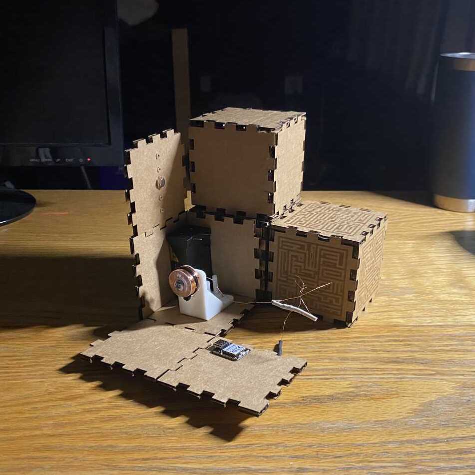
First test:simple circuit with carboard prototypes, single coil and magnet, testing range of attraction.


Second Test:
testing how the coil reacts to two side by side magnets
seeing if this layout is feasible.
Third Test:
testing full range of motion and layout of magnets, two coils and 4 magnets
additonal test: moving with both sides actuated up to a certain weight threshold.
circuit uses two h-bridges to control each coil respectively.

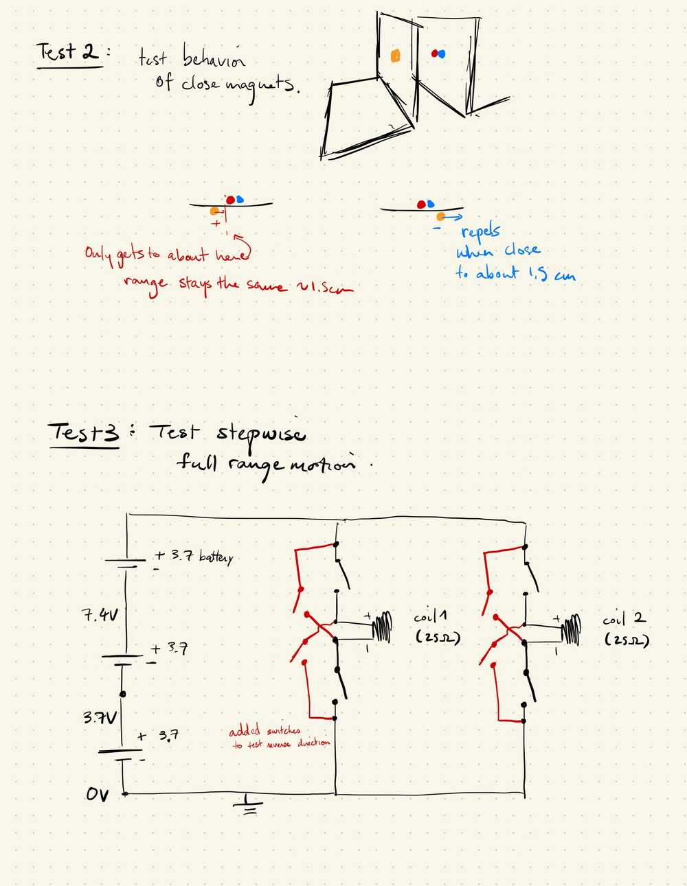

It looks like the positioning of things matters a lot here, further testing will need more accurate positioning using the 3d printed frame.
Additionally, its relatively easy to test more current by adding an extra battery in series, however it seems that there is also some sort of remaining charge/field on the screw core of the electromagnets.
Day 2, iterate 3d printed frame
First print:So I set this to print overnight, and it looks like someone removed it before it was done, maybe it warped or something.

Some issues from testing the failed print, it looks like I can screw on the bolt, but it takes some force and there isn't much clearance for the bolt head.

Ok I set it to print again and here is how it turned out:
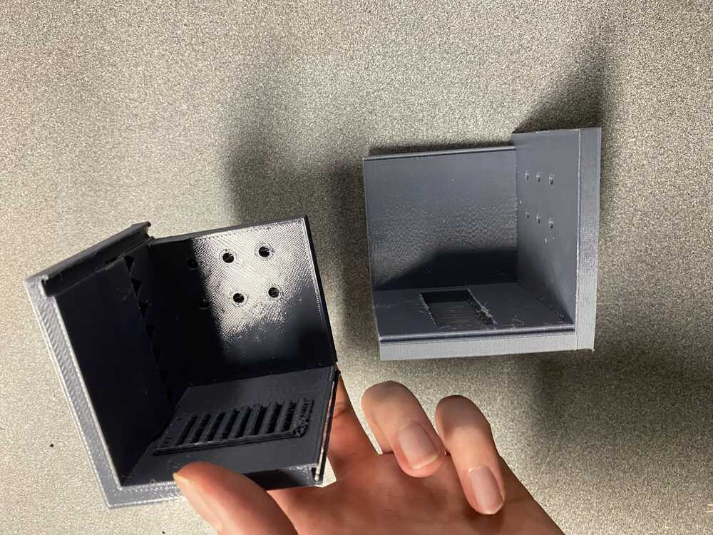

Apart from cutting myself removing the supports, it looks like the locking mechanism had a too tight tolerance, yet had features that were too narrow. Specificially the region in the sliding mechanism that was 0.8mm vanished and the bottom layer of the extruded pattern also was not completely filled in
The magnets and the screw where a little tight as well, and the cover for the magnet slots is not wide enough. It looks like I should have a larger tolerance for everything.
To fix this, I'm thinking of using the lab's 0.25"x0.125" magnets to set things in place instead of the sliding lock mechanism. And I just remembered that glue is also a thing i can do to set the magnets in place instead of an awkward cover
Since this first model is a bit all over the place in terms of being parametric and needs a lot of changes, I'm thinking of just remodeling the whole thing with the sls tolerances and capabilities in mind.
The first step will be to make a bunch of test models for tolerances, as well as a more complete frame based on formlab's design specifications.
I will test the hole tolerances for the magnets, as well as wall thicknesses.

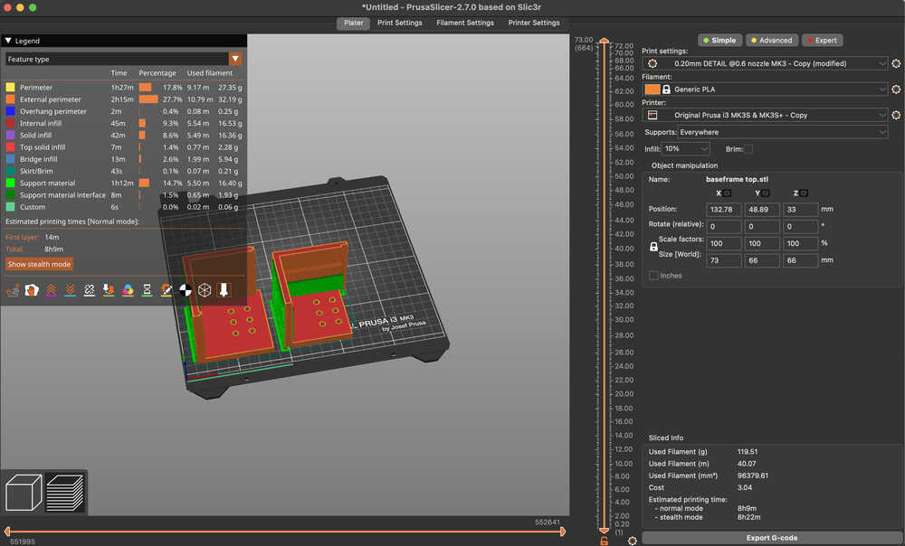
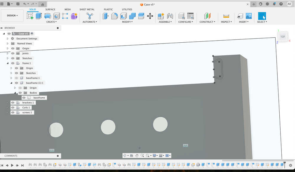
I made a simple frame for the magnets, as well as a simple frame to setup the coils. the important parameters were the distance between magnets(2cm), distance between coils(3cm), and the wall thickness (3mm).


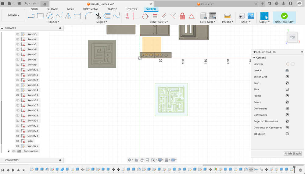
Once that was done I added some slots for magnets to join the top and bottom frames together, and added some test plates for the laputa patterns (using fusion svg insert, although I had to eyeball the placement).
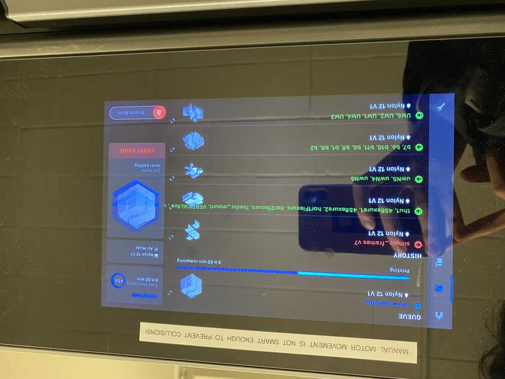
The frames were printed overnight, and I spent around 40min just sifting and dusting off the reminaing powder (wearing a masking gloves and safety glasses) since the sift was full I didn't end up going through all of the prints, but there should be enough for my goal.

After, I brought the prints up to the sandblaster and (after figuring out how to connect the compressed air hose) spent maybe an hour going through the whole stack and then using compressed air to dust off the leftover "sand". Since I didn't get everything in the first pass, I went through a second time to make sure everyithing was the right shape and color.
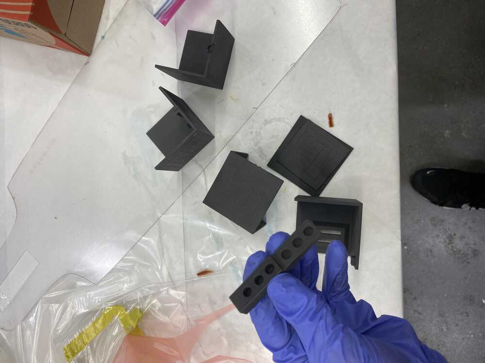

Finally the moment of truth, I tried inserting some magnets in the test holes... and it didn't fit. I was disappointed until I tried fitting into the actual frames, and they fit perfectly! it looks like the wall thickness of the test holes had something to do with it. I got a bit too excited and put a second magnet in the wrong orientation, and now I can't get it out :(. The magnet box happened to be press fit though. I didn't plan for that, but the fillet helps the parts fit nicely


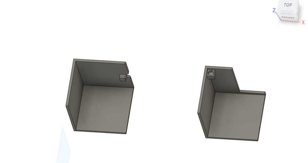
Heres what the assembled cubes should look like:

Some revision notes, the smaller magnets were a bit loosely fitted (I used superglue), and the two slots for the coil brackets where about 2mm too far away from the wall. This is fine since I can adjust the positioning with the screws.
For the magnets, I should have put the locking magnet holes on the other side of the extruded block so that they dont directly face each other. this way I don't have to worry about them pulling off the glue. (which happened)
Day 3, h-bridge control
Since I got some h-bridge boards, I want to write some code for them to test them out. Worst case if I can't get the milled boards to work I might be able to rely on these.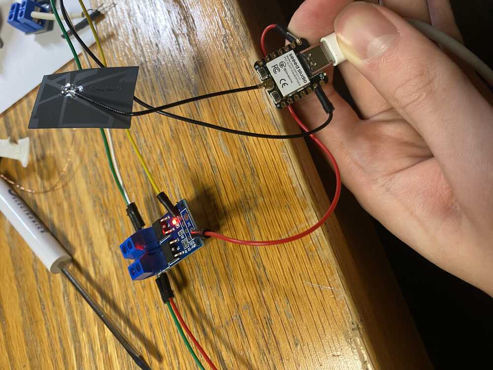
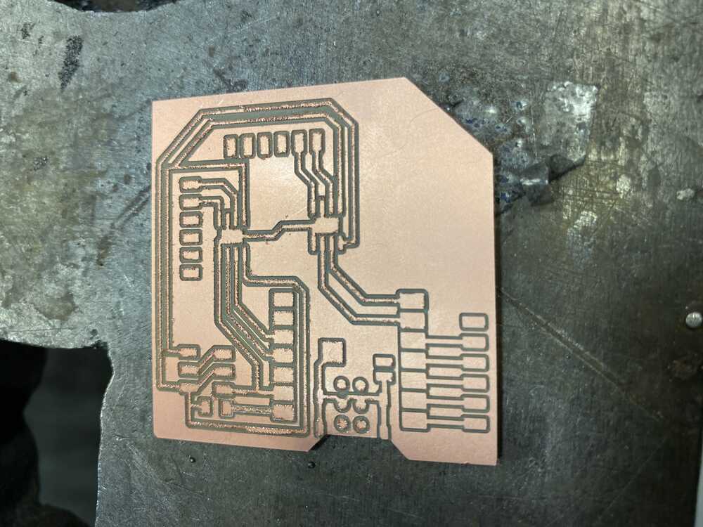
Day 4, circuit design
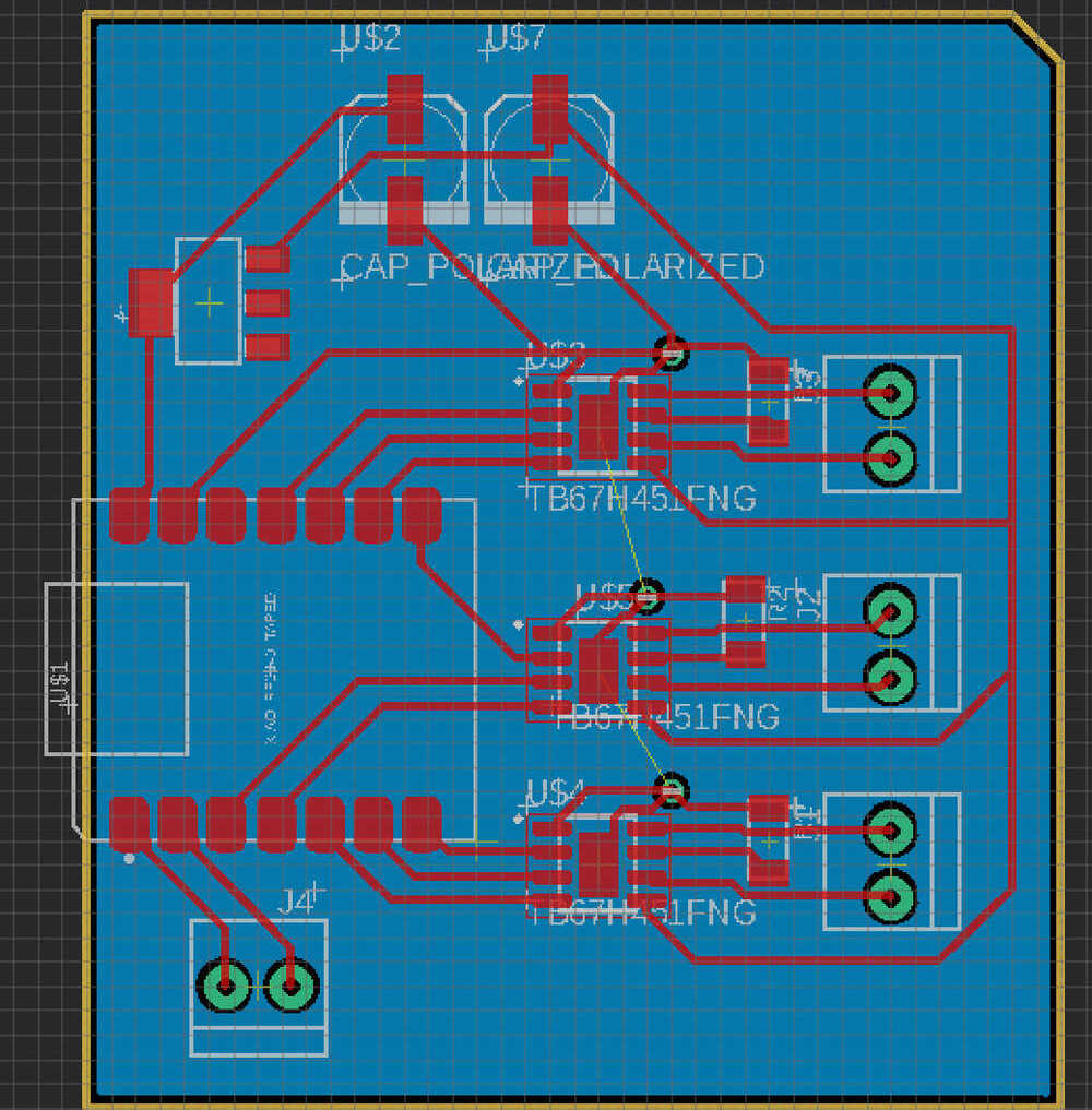
Since last time I ran into a bunch of issues with soldering and milling, I tried to include less components and just make something more like a breakout board that has two h-bridges and support for the batteries.

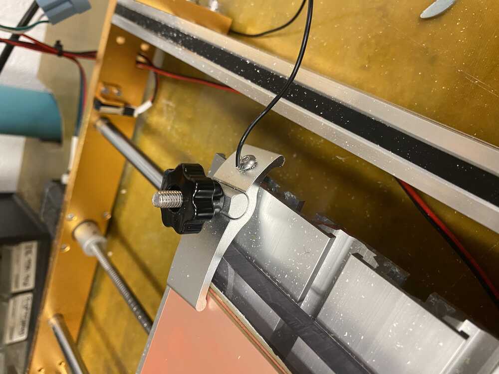
Milling.
I broke another endmill. I got this strange error message after it happened, the probe alarm went off but it didn't stop going down. I made sure the probes where connected and set off the alarm beforehand, that the endmill was tight and at the right distance, so I have no idea what happened. One guess is that the z was so far off from 0 that the macro was still moving fast when it hit the board.
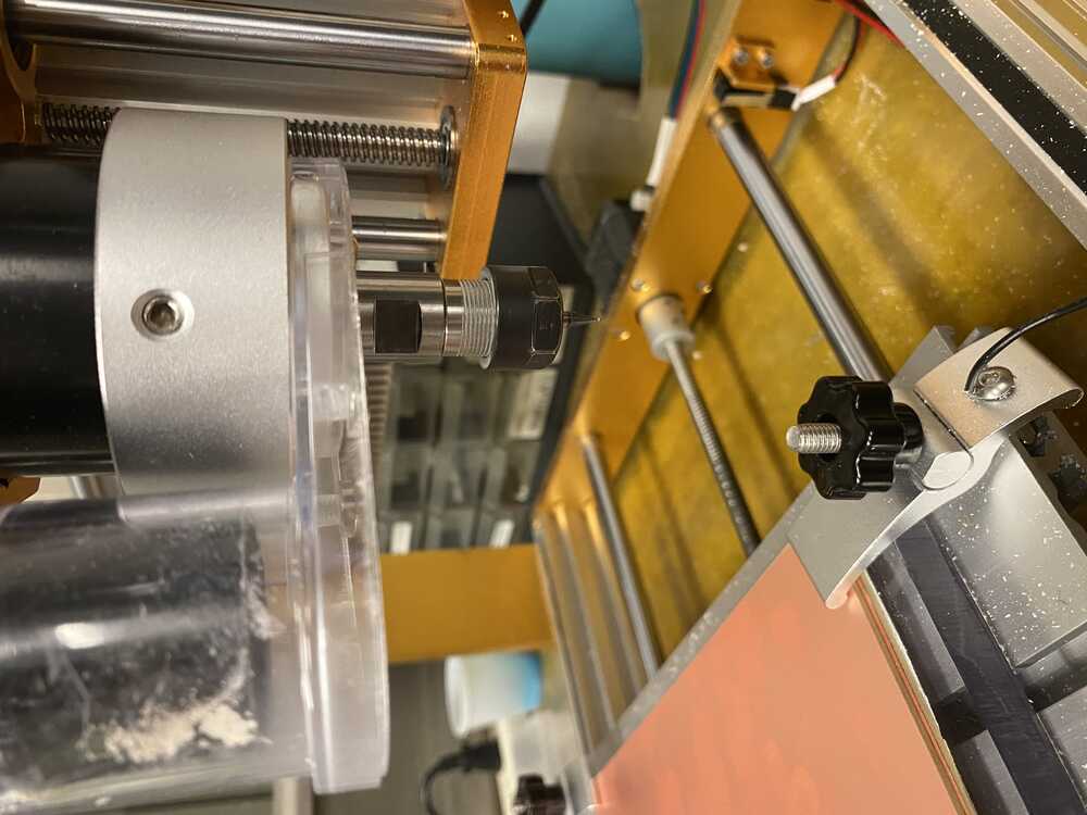

Since I thought this was the last endmill and had a premonition that this would happen I actually took a video of it happening:


Revision edits: move h-bridges to have outputs on the same side as the xiao pins for accessibility and space. While the idea is that the board can be easily mounted on the cover frame with some sticky foam, my layout was a bit annoying.

PS: Also maybe add a flyback diode since the electromagnets act like inductors.
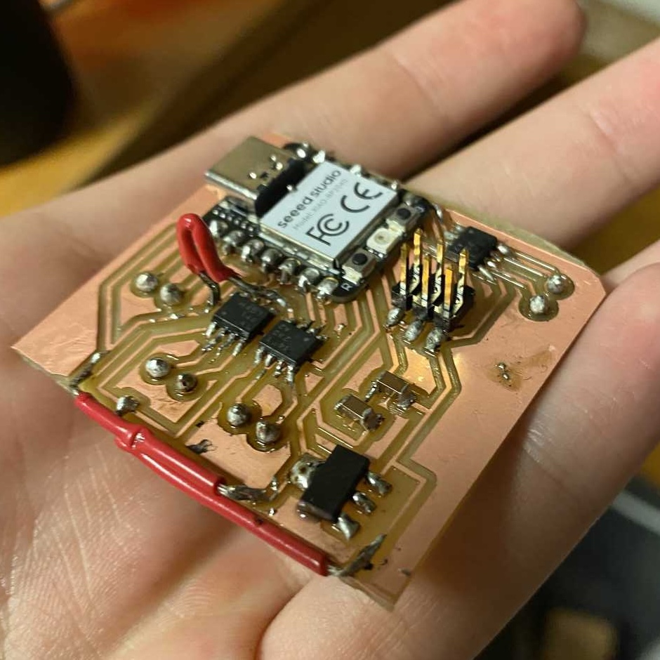
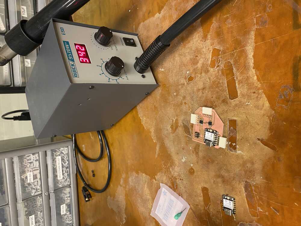
Soldering:
Things have been soldered.


Theres a short. and its between ground and vref. this is terrible. I should go to sleep.
After sleeping, I spent the day working with David and learned:
- using the solder braid
- dump flux on the traces
- don't use too much solder
- sometimes multimeters are wrong and should be replaced.
- test things using a power supply not batteries.
- following existing circuit designs is a good idea
- shorts incomponents that have a ground plate underneath are common
He helped me come up with a way to salvage the board by removing the diode and using a jumper to use the 5v from the board instead of the 11.1V battery powered rail. We also desoldered the esp, added teflon tap, added a jumper to connect the 5v from the usb to the vmotor trace on my board and drilled into the board to get an access point to potentially connect to a battery.


I still had a short between the h-bridge inputs and ground and vref, I decided to give up and just mill a new board.


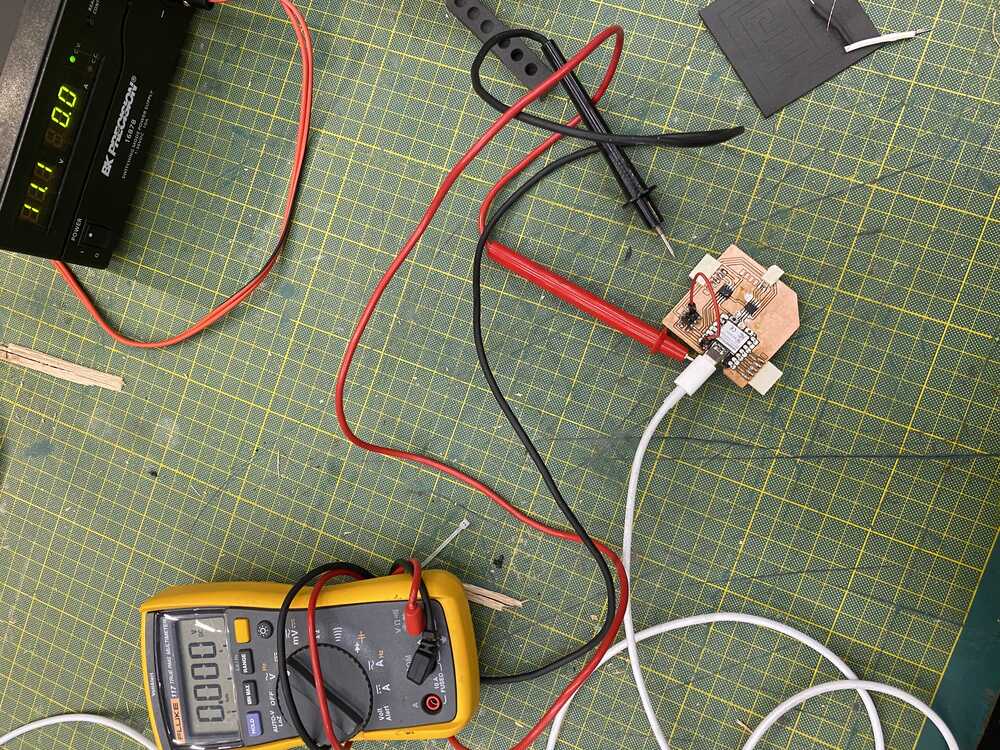
Now that I have a clean board (hopefully), I should make sure I can actually use the h-bridges correctly. After trying to set the d10 and d9 pins on high and low, which works just as expected. Although there is some floating voltages in the other pins. hopefully I can fix that just by setting some values. Since I'm not completely sure what vref values I should use (probably 3.3V since thats the range of inputs im using), I will connect the 5V to the hbridge's Vm and 0V to Vref, and then try 3.3V to Vref.
And here comes the moment of truth... I upload the code, and plug in the 5V... is it gonna smoke and explode?? NO! IT ACUTALLY WORKED
and so, after countless hours designing in eagle, milling, and solder, and of course debugging, I finally managed to use an h-bridge with the xiao. Now its time to test the reverse and the other h-brdige, hopefully I didn't celebrate too soon. It all works. I am very happy right now. It looks like I was right about vref as well, setting it to 0V set all the outputs on. Here's the test code
const int coil1_in1 = D9;
const int coil1_in2 = D10;
const int coil2_in1 = D6;
const int coil2_in2 = D5;
const int vref = D8;


void setup() {
  // not sure if this is necessary since it works anyway
  pinMode(coil1_in1, OUTPUT);
  pinMode(coil1_in2, OUTPUT);
  pinMode(coil2_in1, OUTPUT);
  pinMode(coil2_in2, OUTPUT);
  pinMode(vref, OUTPUT);
}

void loop() {
  	// h-bridge test
  	// set coil 1 in reverse
	digitalWrite(coil1_in1, LOW);
	digitalWrite(coil1_in2, HIGH);/
	// set coil 2 forward
	digitalWrite(coil2_in1, HIGH);
	digitalWrite(coil2_in2, LOW);
	// set digital logic reference voltage
	digitalWrite(vref, HIGH);
      delay(1000);
}
Ok, I had some issues because it looks like I've been setting the strapping pins to arbitrary values, and had to reset the board/ the software unplug etc. Now it works again. Heres the updated code
Now that I have the h-bridge working, the next step is to connect it to a stronger power source. Unfortunately, after connecting a 16V source to the Vmotor pins and the ground to the xiao's ground, the board died. I'm not sure what happened, I was measuring the voltage while plugged in to the 10A max current socket and felt things heat up so its possible that some short happened that way. Maybe since I dont have any current limiting resistors/capacitors etc. there could have been some random current spike that blasted the board.
Anyway, now that I fried the board, I spent some time desoldering and soldering my last functional esp32 to the board. This time I'm going to be very careful with adding a power source since I don't want to fry my last board. A basic test I did was to check for connectivity, and then to use a low powered generator and check for current by connecting the power source in series with the amp meter and to check if there any current. Since there was some current, I decided to stop there. (even though I was very tempted just to wire the 11V again)

Day 5, networking and interface
Now that I've milled the board, and it kind of works, I want to connect to it remotely. Since I'm running out of time (its not actually day 5), I decided to follow the simplest tutorial I could find.https://randomnerdtutorials.com/esp32-web-server-arduino-ide/
This builds on top of the basics I used for networking week and is about as simple I could ask for. Although theres a lot more I want to do, I should just aim to get this working for my project so I can go to bed.
It was actually pretty straightforward and worked on the first few tries. I am just modifying the code from the tutorial to drive an h-bridge instead of turning on an LED. Heres the code
(PS I forgot to take a picture of the interface, and now I don't have the esp to connect to anymore)
Instead, here is basically what it should look like, but with "coil1" and "coil2" as buttons to drive them forward or off:
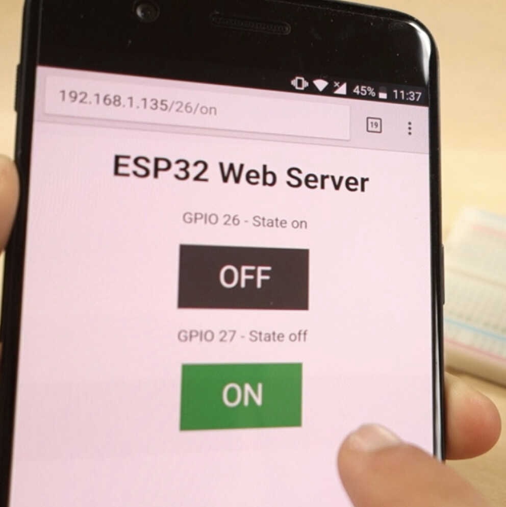
An issue that I found is that although the esp is outputing the right values for the h-bridge inputs, the 2nd h-bridge is not turning on. I also noticed that vref is around 2 even though its set to 3.3V so maybe thats affecting the h-bridge, but the other one works fine so maybe I should just replace it.
I'm going to stop this project here for the presentation. Theres a lot that can be built off of this so I hope I can keep working on it.
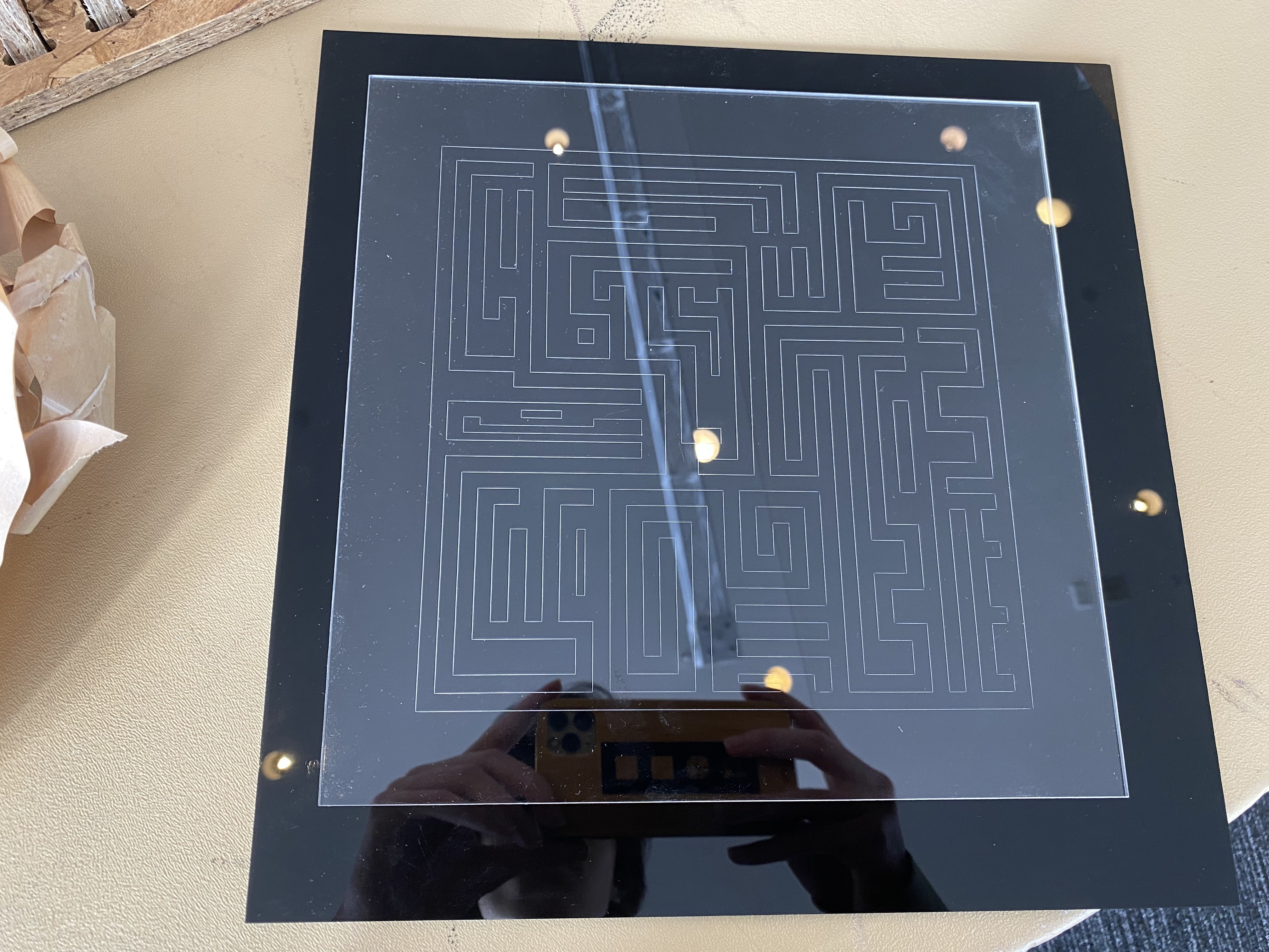
Extra: laser cut base
Maybe there is some argument that I used acrylic so that the blocks would have less friction, but it was mostly because it looks cool, and that it would contribute to the "subtractive manufactruing" part of the final project that is mostly just milling boards so far.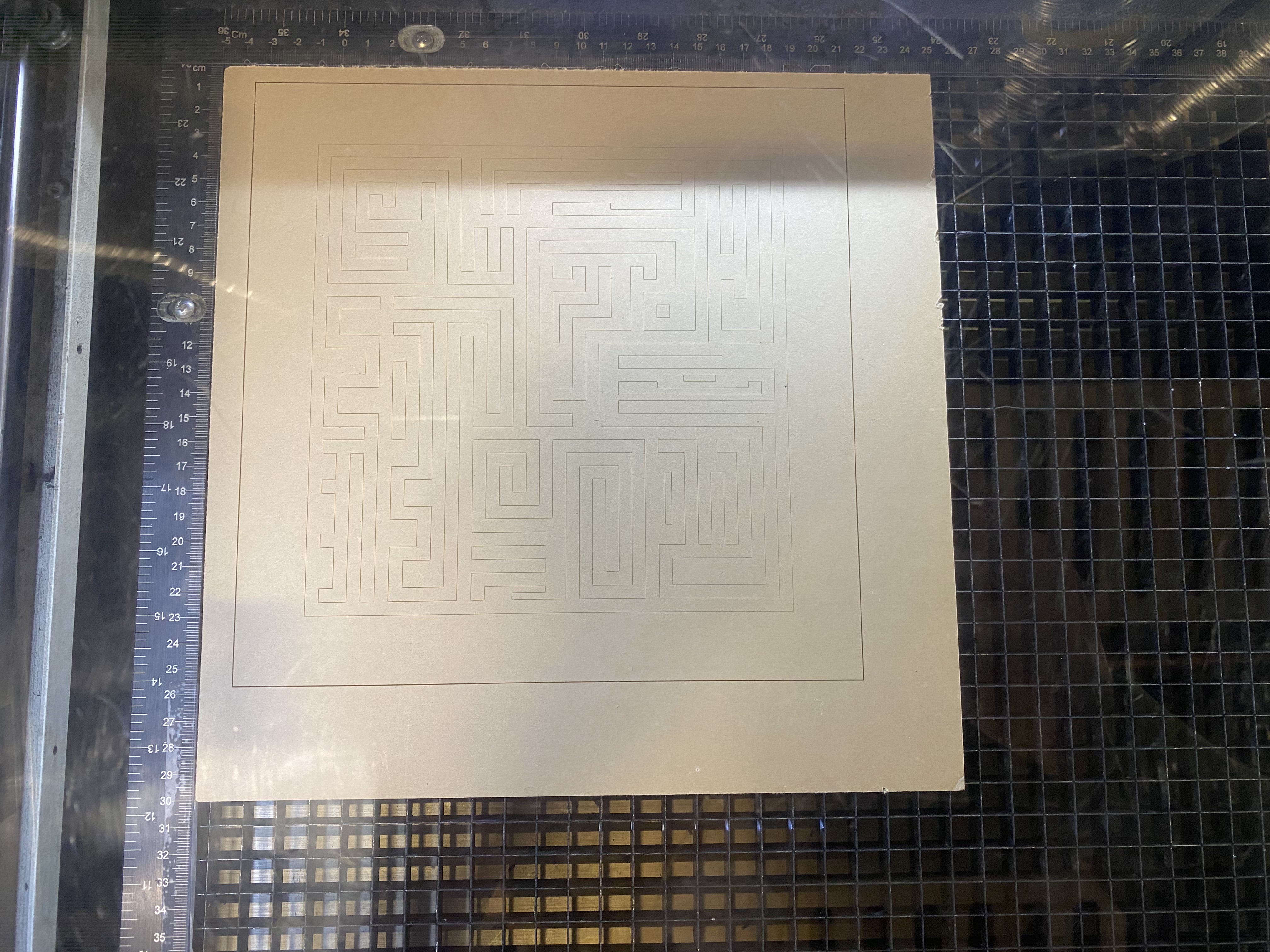

presentation

Next steps:
- ask about power supply with esp32 (current readings)
- bring all the stuff to the media lab before 1:30 (1.5h window after my 6.1010 final)
- setup stuff
- prepare video of it working.
steps for after demo:
- finish documentation
- learn css so I dont have to linebreak all the time
- final sls print iteration
- add capacitors to circuit board maybe, figure out battery issue
- use strong battery power, use lipo to power xiao
- get the h-bridges working
- setup a better interface for controlling h-bridges
- create sequence in code for translation
- get a better understanding of the circuit and how electromagnets are controled, add flyback diode
- learn modular things
- experiment with closed loop PID control with hall effect sensors