Week 10 documentation
Overview
For this week, the plan is to:
- solder my board
- write some code to make my electromagnets work using the board.
- print out my model from week4
relevant ideas from lecture
super capacitors as easily chargeable batery bank
wireless power transfer
Ramp up and down so that you get in between phases, microstepping
Soldering
Since I didn't get to soldering much in the past weeks, I'll make sure to work on it this week.
Process notes
- put a tiny bit of solder on the tip
- heat up traces with tip
- once hot enough, add solder to the copper traces, it should melt.
- remove nib, add component leg.
- heat up both the leg and the trace and remelt the solder on the copper
- once the component is attached, now heat the other parts (both leg and copper) and add solder
extra notes:
- figure out how this ts 101 soldering iron works by reading the manual
first issue:
- solder isnt melting even though the iron says its reached 300C, so I set it to 360C but its still melting inconsistently
- two legs got soldered together, and either i don't know how to use the desoldering stick or it doesn't work in this case.
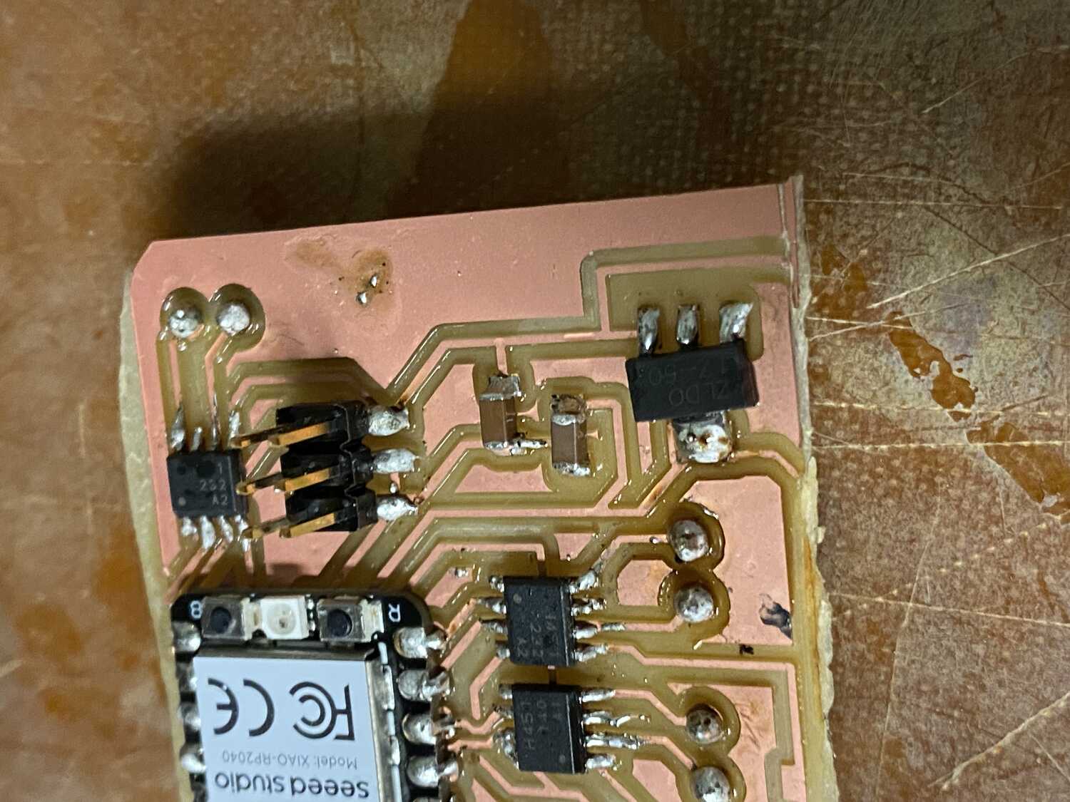
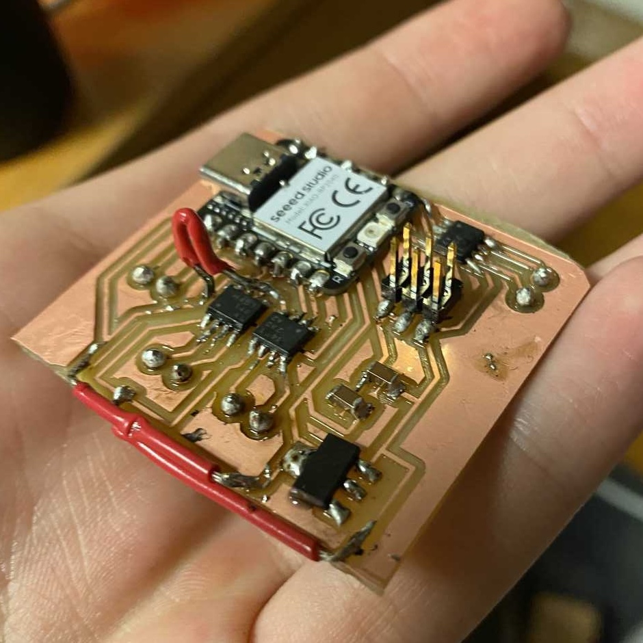
- after using a better iron and flux, I got the h-bridges on, kinda, with marginal amounts of solder
Things I have learned after many hours of soldering
- give up if solder tip not heating well(super annoying)
- small components with small legs are much harder to solder (i tried to solder these first for some reason)
- get a light so you can actually see (I used my phone)
- don't use a heat gun to solder and burn yourself, solder through-hole components upside down
- the tabs below the xiao are not necessary (which is good because i failed at soldering them anyway)
Heating up the leg and letting it melt the solder is a distant dream when you had a small component with small legs and a soldering iron that isnt hot at the tip.
I look forward to later when I do this board again and solder nice joints.
After talking with Jake for a bit I learned that I dont actually need to use the vin under the board, but I should be careful
not to use the usb and a battery at the same time, or put a diode stopping current from flowing from the battery to the laptop.
Fixing the cropped board and missing connections with jumpers:
ripped out a trace with the third jumper
gave up on the last jumper since it wasnt sticking, wont use the third h-bridge for a while probably
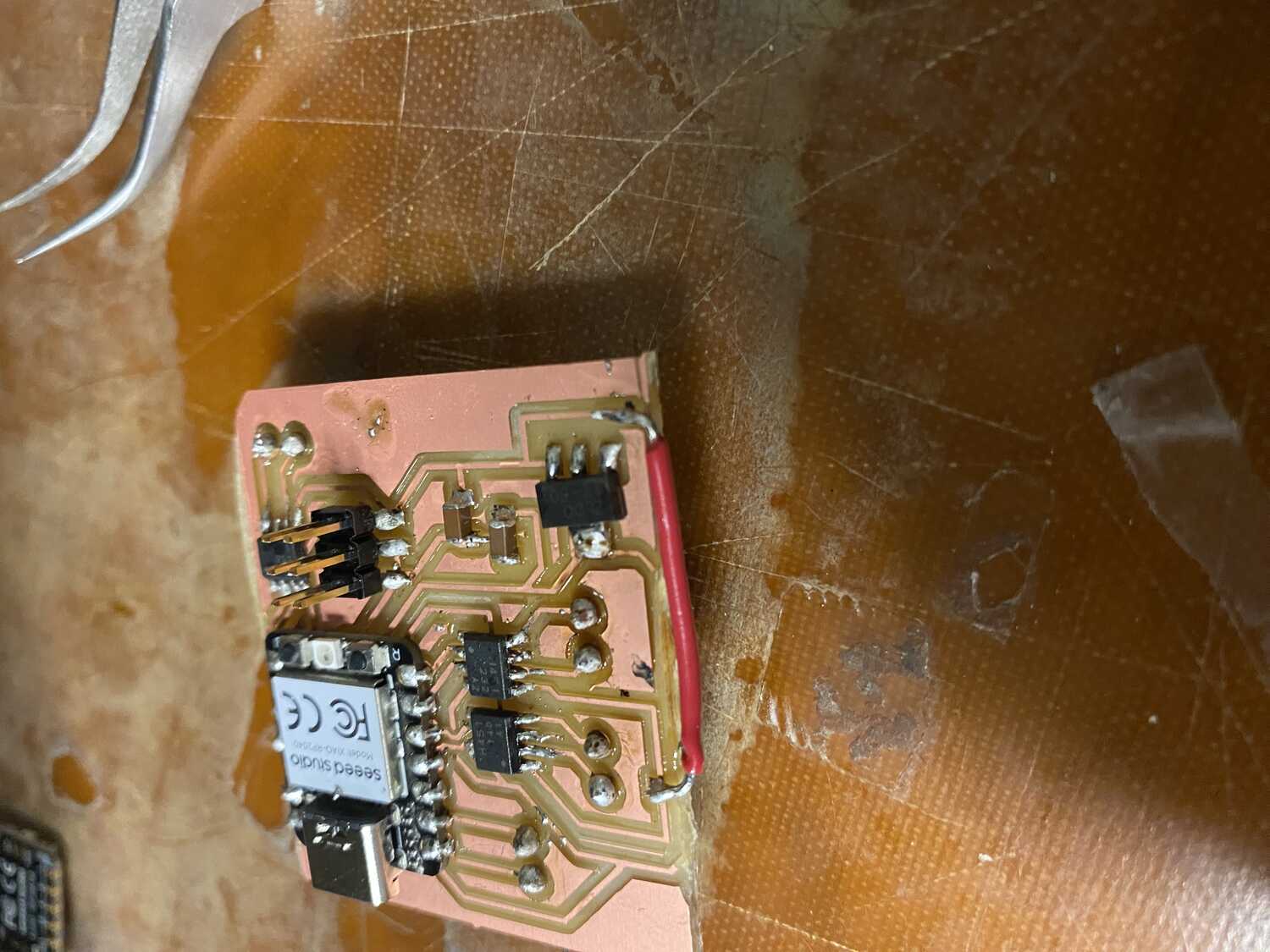
Turns out heating up a short wire melts the rubber.
havent grounded the voltage regulator oops.
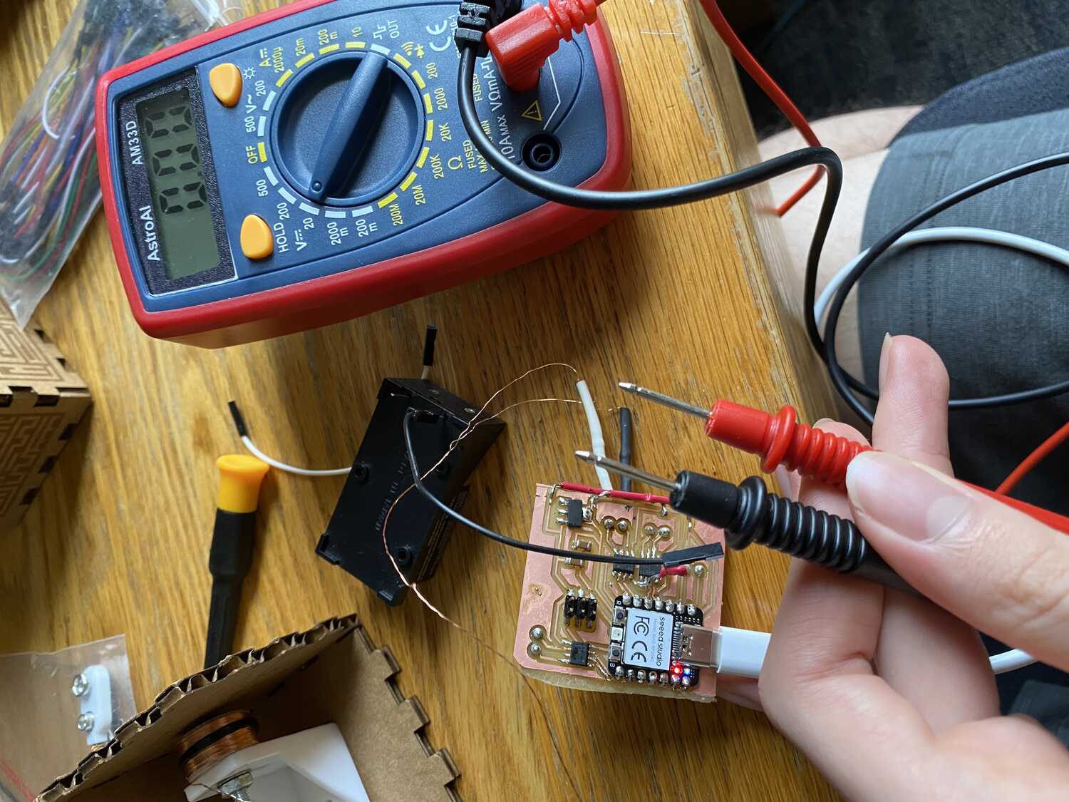
Testing continuity using a multimeter, suprisingly everything seems connected!
Controlling h-bridges
Anyway since theres only an hour left before lecture, I'm gonna try to quickly test sending a signal to the h-bridge to see if the motor sees any of it.
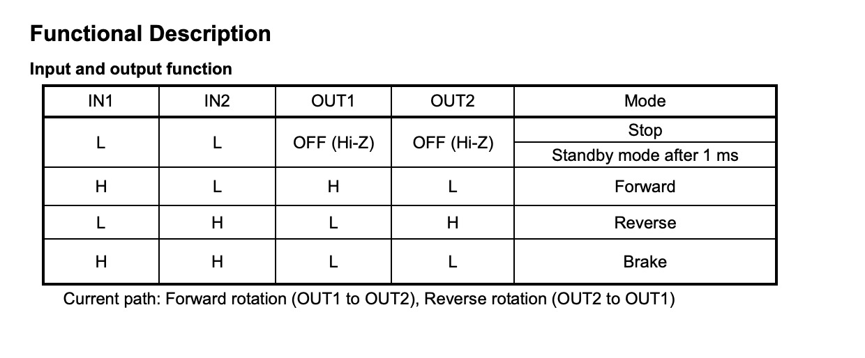
Looking at the datasheet I found this helpful chart:
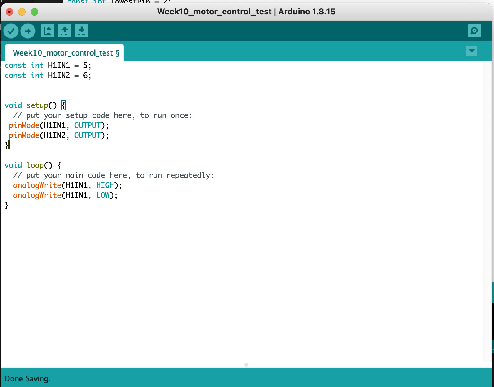
referencing some sample analogwrite code I get this:
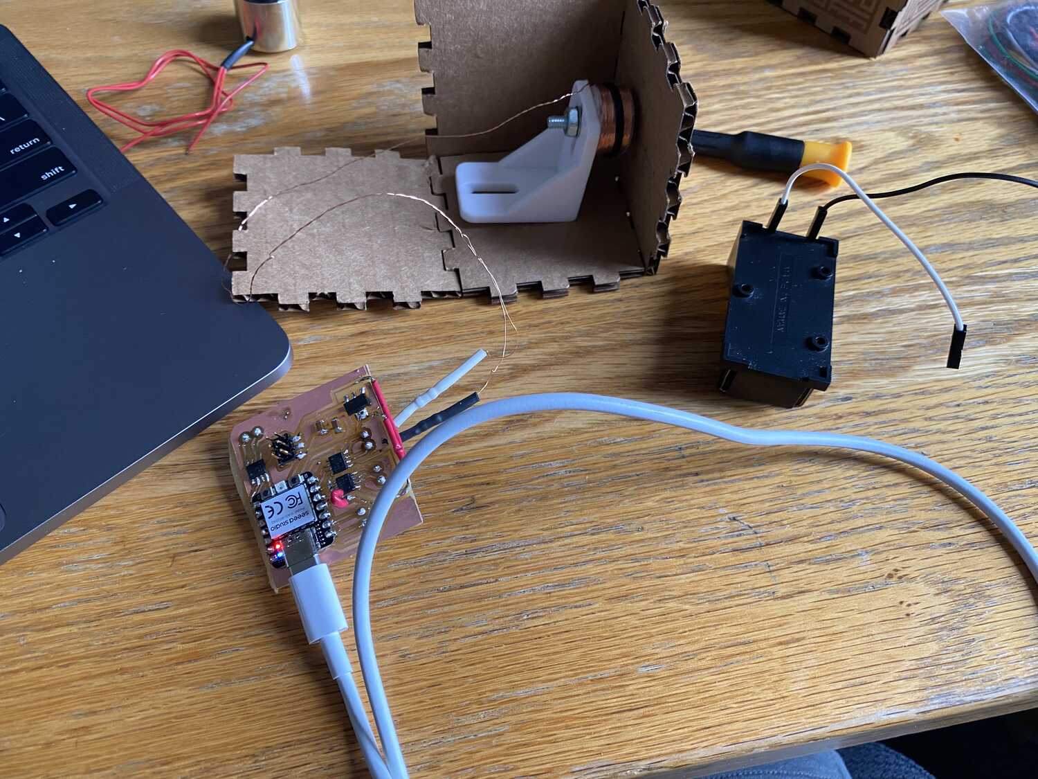
First I test the outputs from the xiao to make sure it works.
Making sure I dont have the usbc and battery in at the same time, i wire the battery and remove the usb. (Note to myself: trim the board a bit at the usb connection)
Now, since I know that the regulator adjust pin isnt grounded I know some funky stuff might happen.
Measuring the voltage at the input battery pins, they now read ~1.5V instead of ~9V and the battery is heatting up. not really a good sign, probably a short somewhere.
A lot of pins are at 0.6V and the adjust pin of the vregulator is also at 0.6 which isnt good either.
Next, I'll test again once I fix the regulator's pin.
Welp. I managed to do 1.5 out of my 3 objectives. (I write code and print out the board during the final project week)