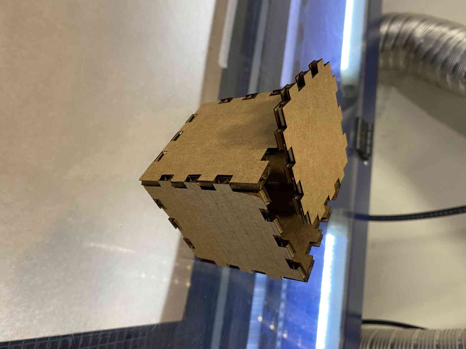
- get a box to house electronics
- slice a geometry
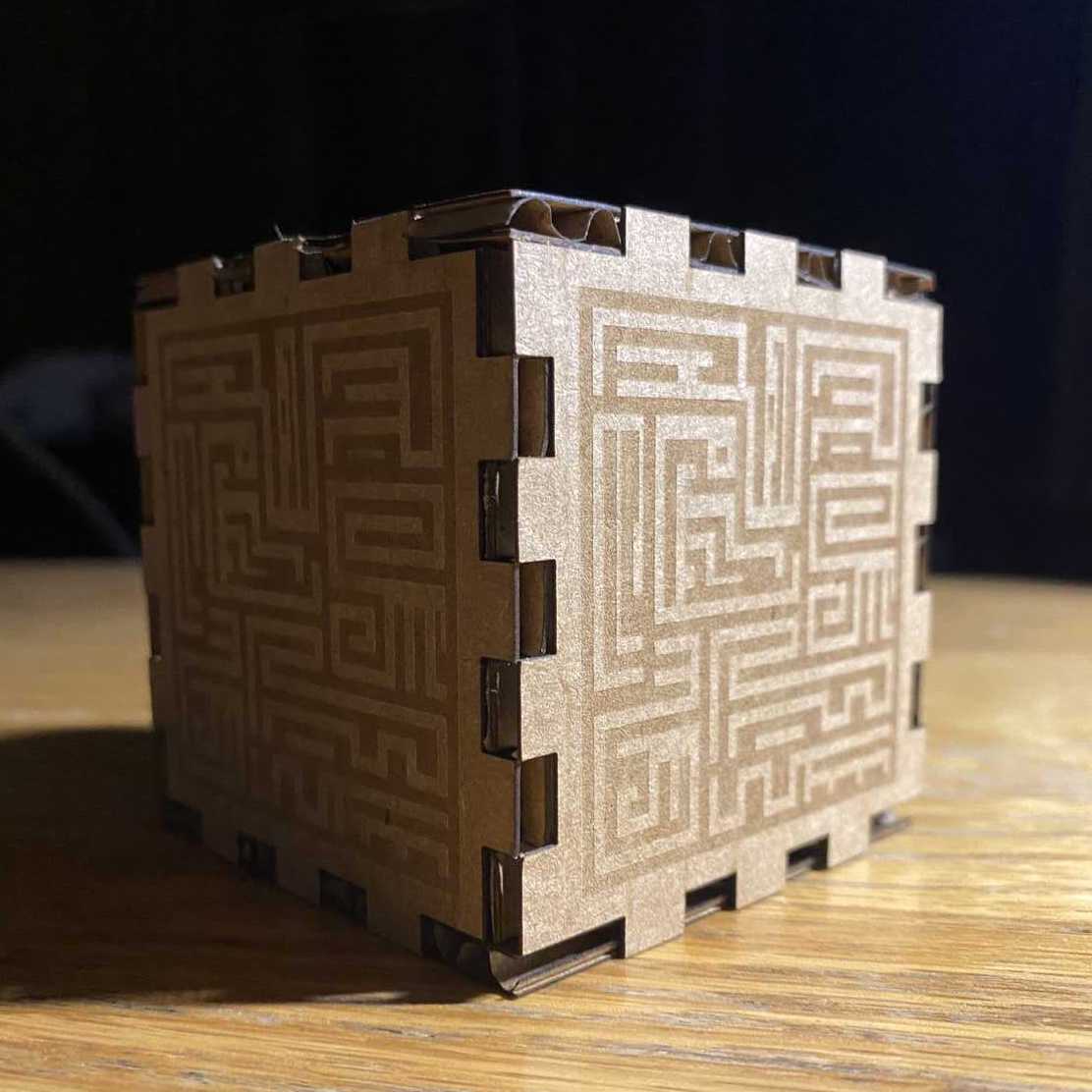
- make a looks like model
- sketch
-image
- download fusion
- update mac
- clear 30Gb of storage
- wait 3h in limbo
- get through a bunch of pop ups
- create box
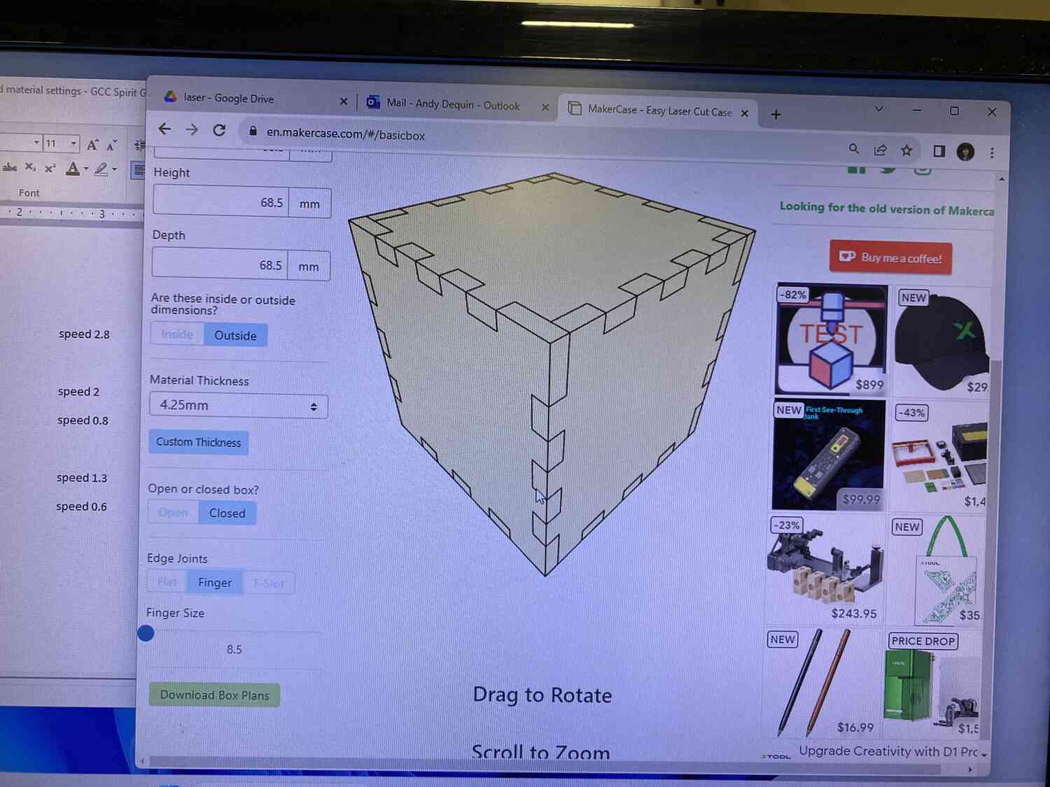
- lose patience and go to a finger box generator
- learn how to manipulate parameters
- take measurements to reference
- create constrained parametric geometry for each piece
- create brackets to model the layout and figure out the clearances
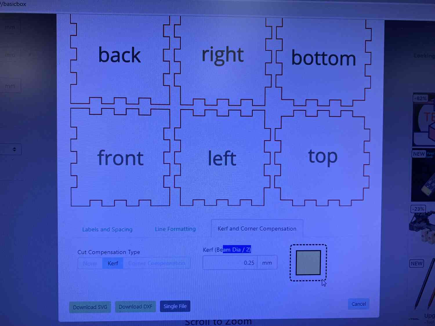
- export as svg
- add 2d engraving for fun
- TO DO use fusion slicer to make sliced sphere
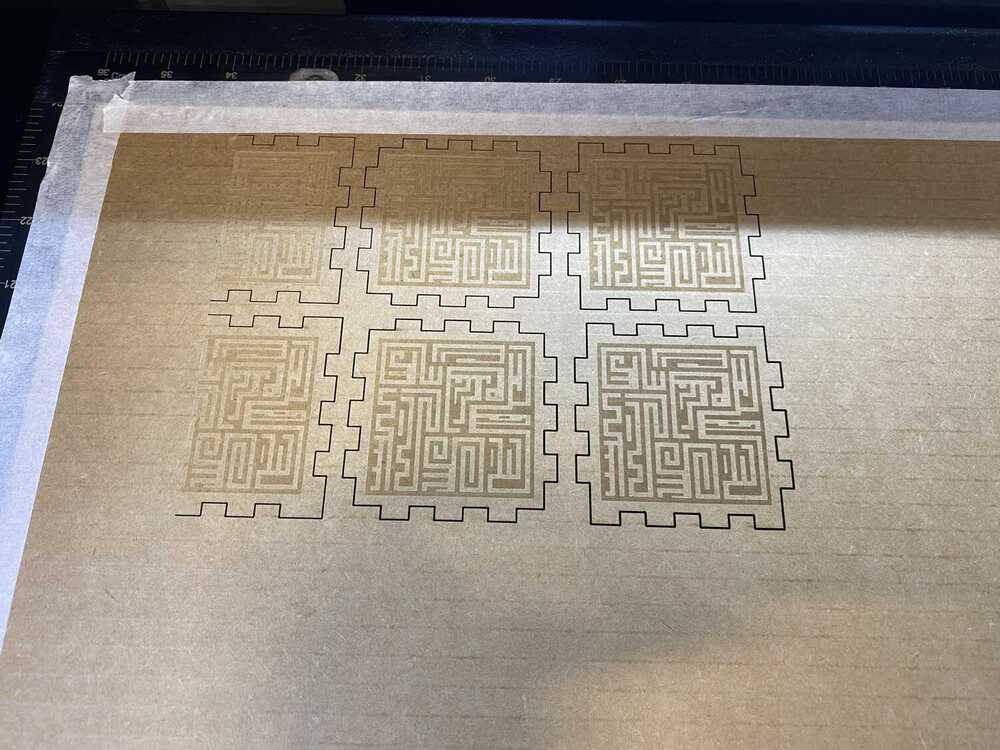
- cutting
- test cut for kerf
- test design on carboard
- make looks-like using acrylic
- acrylic glue for the finger joint box?
Making stickers
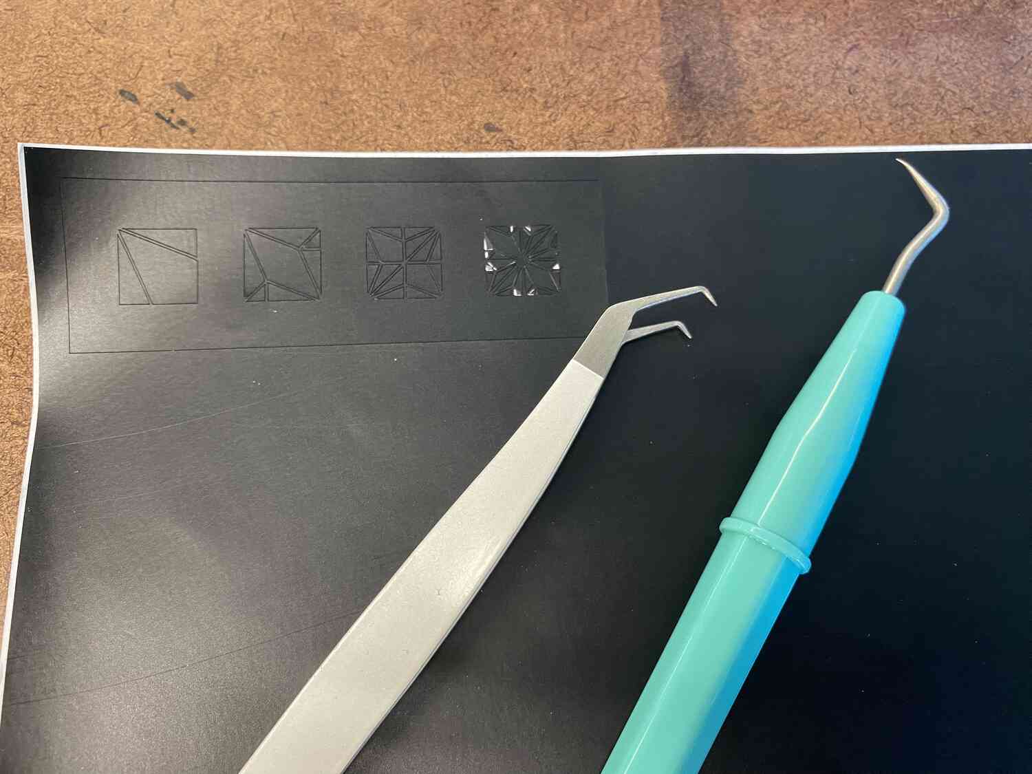
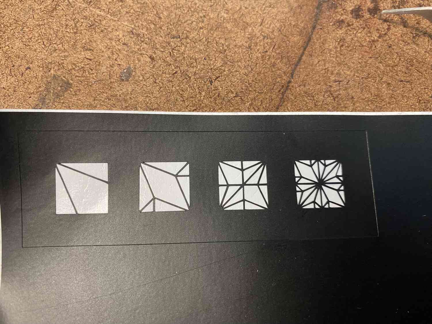
For this week's assignment I first started by making some vinyl cut stickers. Since I already knew how to make the svg files I had in mind,
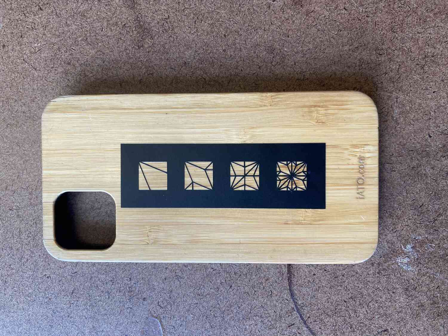
and I have some experience on the cricut, this was a very straightforward process. I used the cube's pattern that I traced last week to cut, as well
as the four origami traditional bases whose design I like to use for things like these. I also created a simplified logo for my website's favicon by creating the basic
design, and then editing the svg directly using an online svg editor.
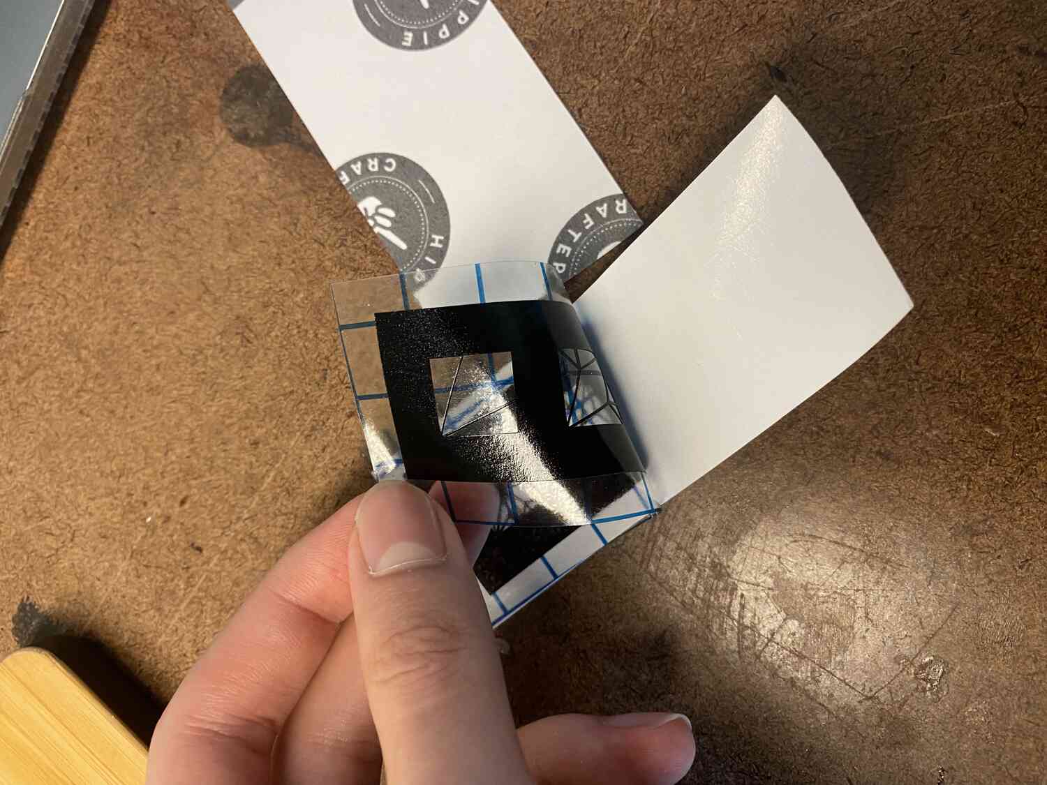
After cutting in cricut, there is a weeding process using tweezers.
And finally theres the tranfer process that uses transfer tape.
I should mention that I also had some experiments with blender making a cloud and rhino projecting a rotated cube, but decided to move forward with these two options.
Making prototypes that I can rapidly test with.
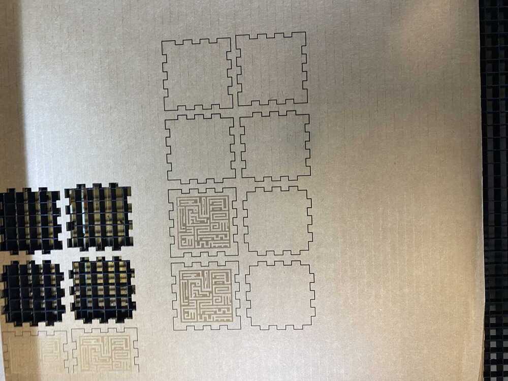
Ok. The first attempt was a little cluttered, I would like to generate the box more cleanly and
add an engraving and some evenly spaced holes.
Ill start by sketching a square on the xy plane. For the sake of time, I simply decided to insert the dxf of the fingbox design I used and add on the engraving pattern that I made previously.
While trying to drag around the color ordering, I used control alt click and it closed the software with no warning. Luckily it saved a backup.
It looks like the engraving goes before any vector cuts by default, regardless of color arrangement.
oops, looks like the cutting bed was different than the actual bed for some reason. It looks like I actually ignored a warning that the print settings raised.
Instead of fixing the problem of the bed, I simply shift it over by some margin in corel draw and click print preview to verify. (the solution is to go to settings and click the extend check box)
All good now! I repeat the 2 sides that didn't make it on the first cut and cut out panels for 2 more boxes. This should be enough for more prototyping.
And that's it for now! I have a looks like model and some more boxes that I can put holes and to arrange my screws and stick things to.
Back to the cad
Deriving parameters
I would like to clean up the drawing for my own satisfaction.
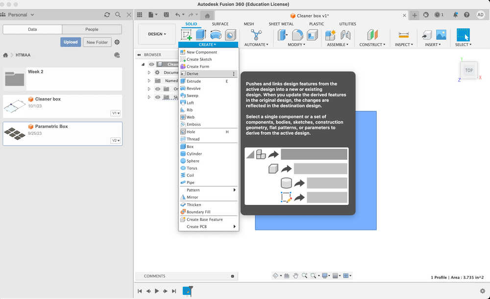
The first step is to somehow import all the parameters from my previous drawing.
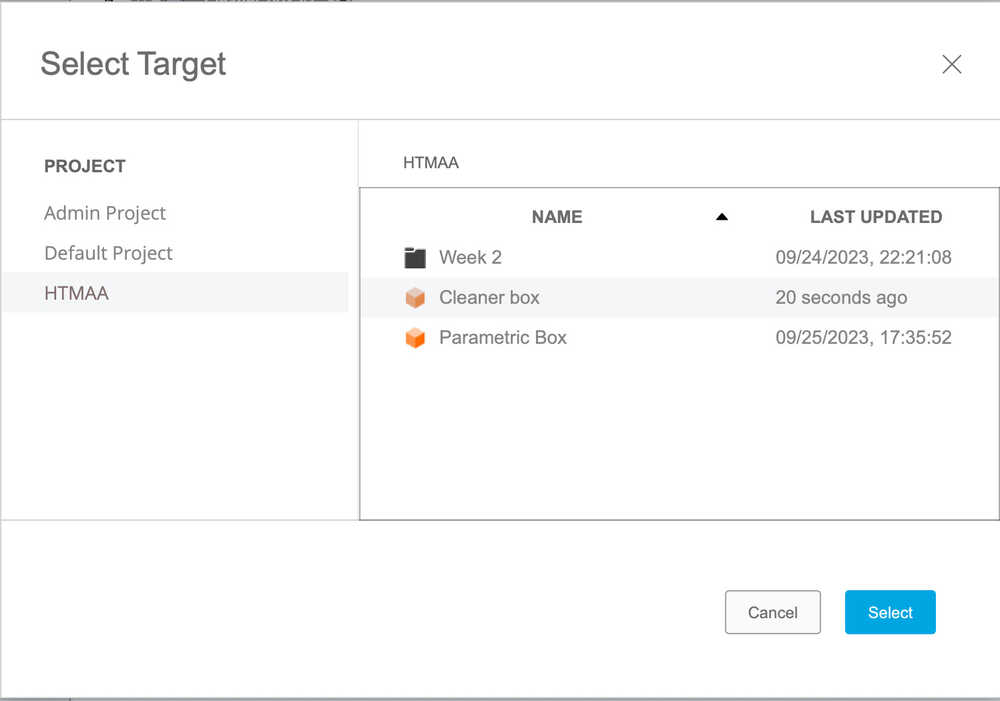
There is a derive feature, but it looks like I can't use it for a seperate document, I'll just screenshot and do it by hand this time.
Nevermind I got it to work! Although it looks like the parameters are linked to the original document which makes me uncomfortable.
Maybe I can get around this by favoriting the parameters.
maybe not, it doesn't let me. Instead, I copied them by referencing the derived parameters, just in case. I found the derive feature in the timeline of the new document and deleted it.
Now the parameters are not linked.
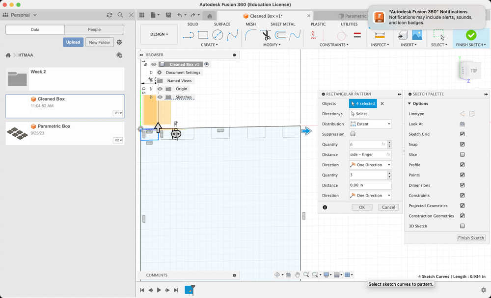
Now, I'll start by creating a component and sketching a square. Next, remove the holes for the finger joints. I'll make a square that I dimension (shortcut d) using my thickness and fingerlength parameters.
Then, using the rectangular pattern in one direction I can create a row of joints that I control with an integer parameter for the number of fingers, in the other
I'll make 2 copies so that I get a second row along the bottom edge.
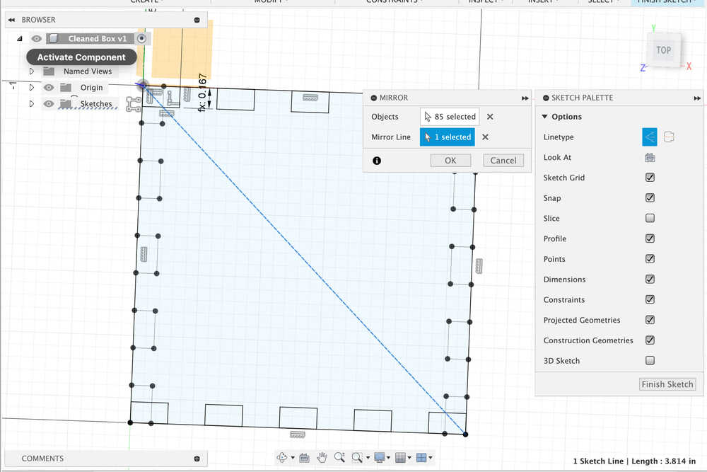
Create a mirror copy along the diagonal so that everything is symmetric. Do this by creating a construction line along the diagonal and using the mirror function.
I suspect theres a better way to do this, but I don't know it.
After extruding it by the thickness parameter, I got the base in a slightly less cluttered way!