Week 4 documentation

goals for the week
1. 3D scan an origami piece
2. 3D print tiny linked polyhedra
3. CAD my prototype parametrically
4. 3D print and test housing for components
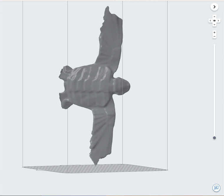
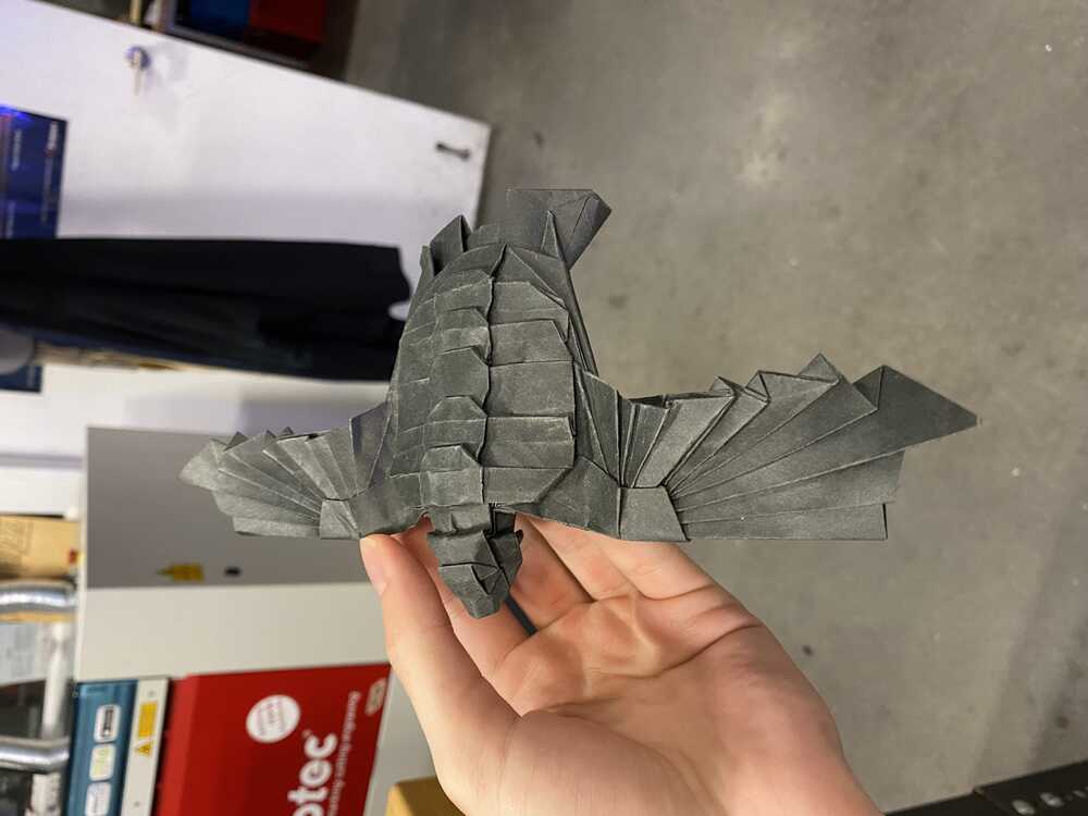
Part 1: 3D scan an origami piece
The quick training at the lab shows a very straightforward process for 3D scanning:1. place part on a flat surface with black guide lines (take extra precaution if black or reflective)
2. take out the scanner, turn it on, and create a new project
3. press start and walk around the object while keeping in range (the object should be highlighted in green, not red)
4. save the project to SD
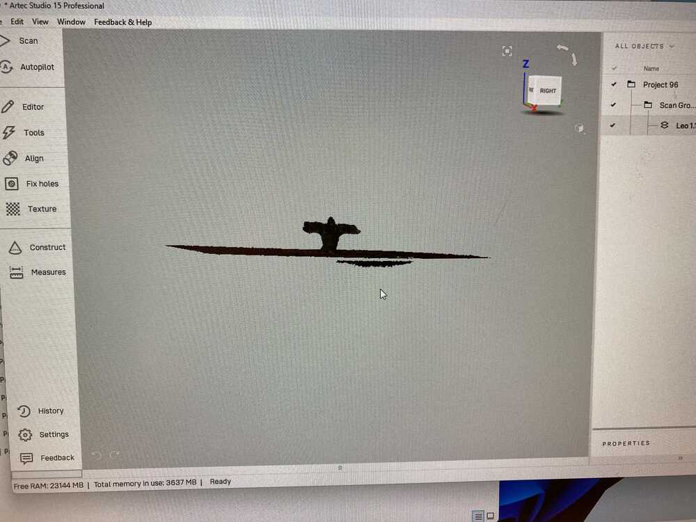
5. open it on a computer with artec studio (the processing software for the scanner)
6. right click the object in the hierarchy and click show
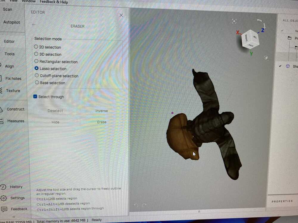
7. check for damaged frames and delete them
8. click autopilot and follow the directions
9. export to stl or wlt with png texture for printing on the Strataysis
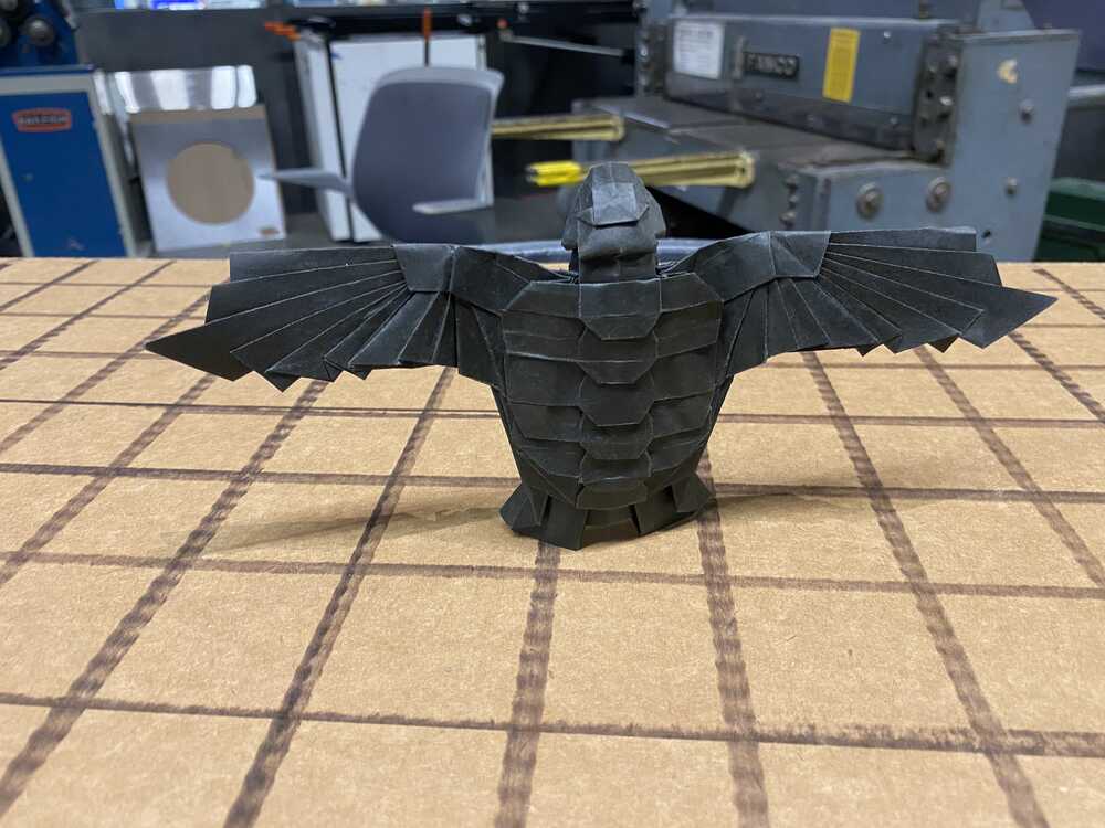
For my scan I want to scan this black flying turtle I designed 2 years ago:
My setup:


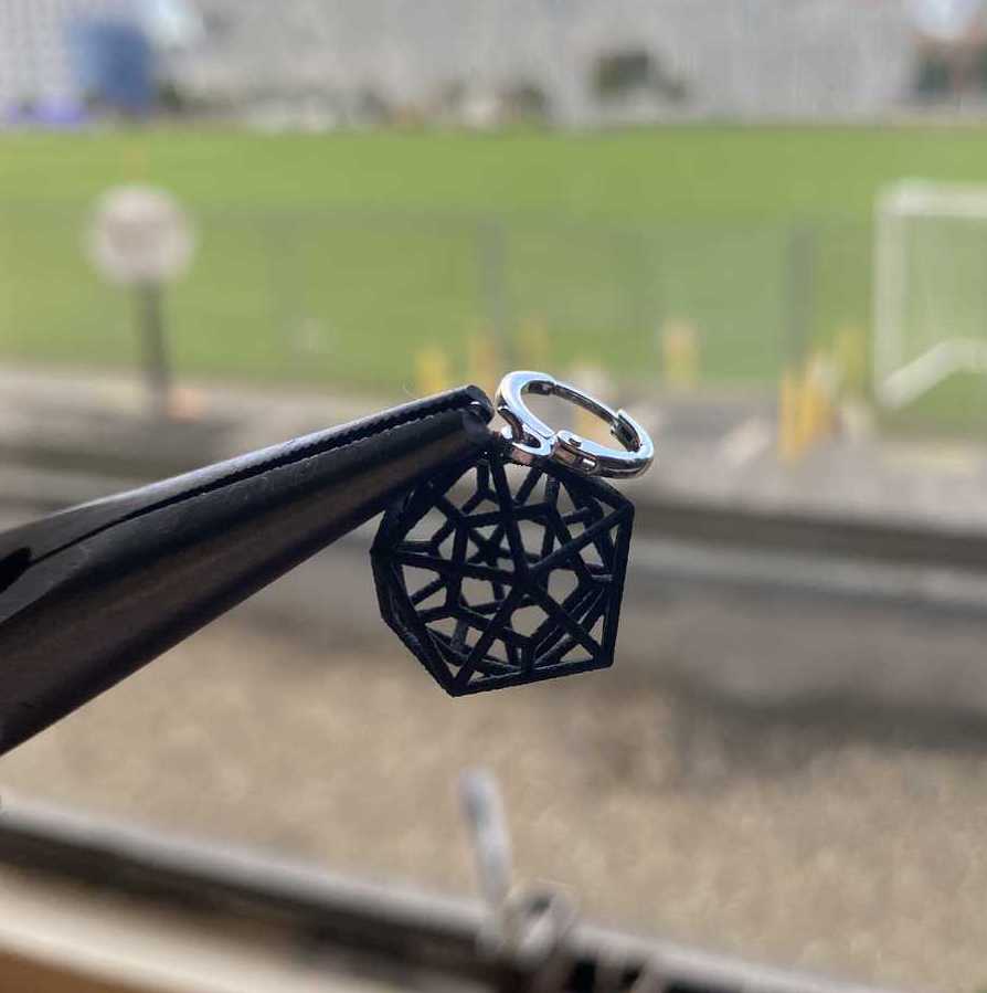
Part 2: 3D print tiny linked polyhedra
This is a projected that I started just before the semester. Since I didnt get into the class last year, I started this in case I did get in. This project has a few parts:
- Finding which polyhedra to use and how to construct them
- Designing the polyhedra in CAD
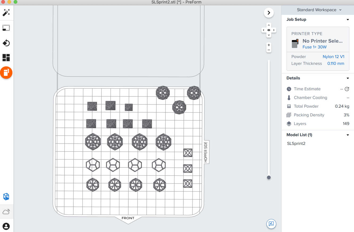
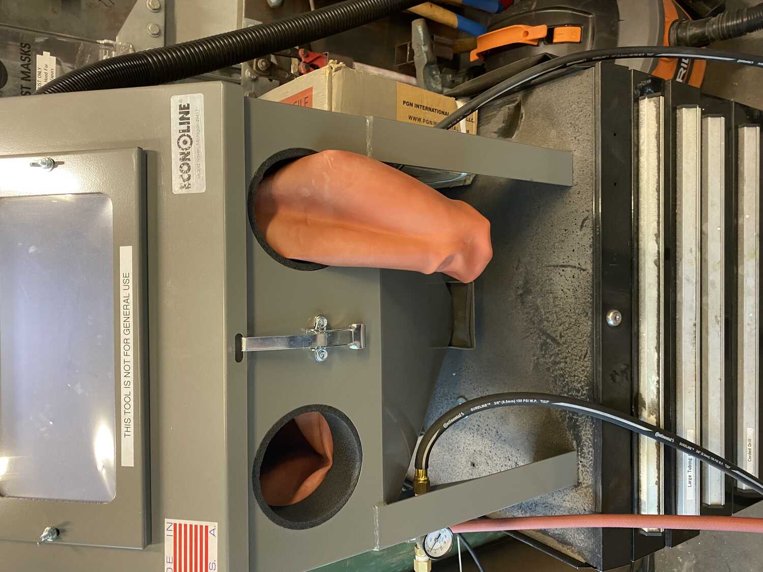
- Printing and processing
- Iterating to find good tolerances
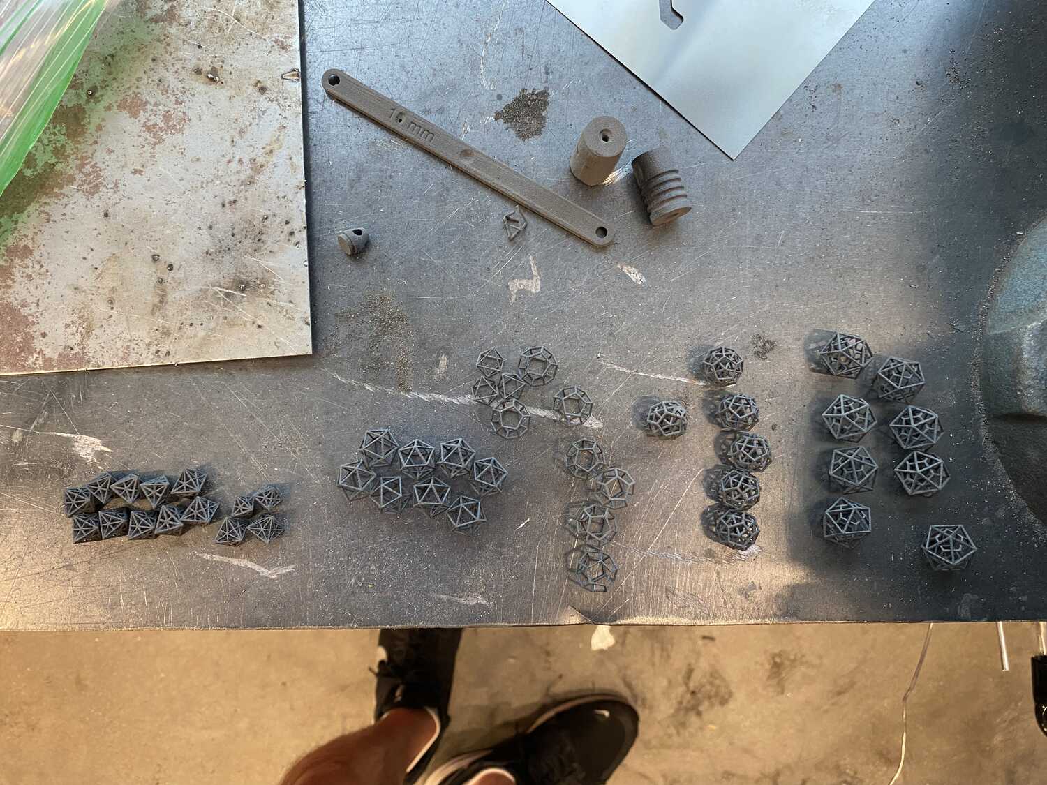
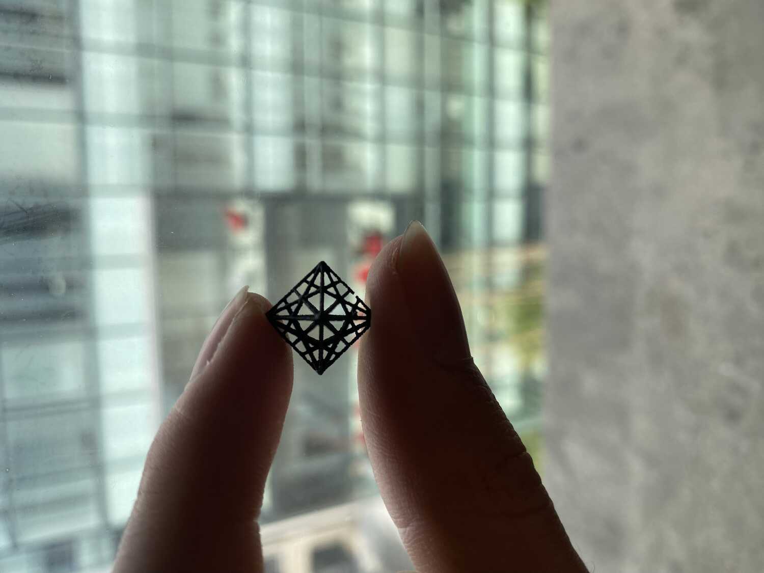
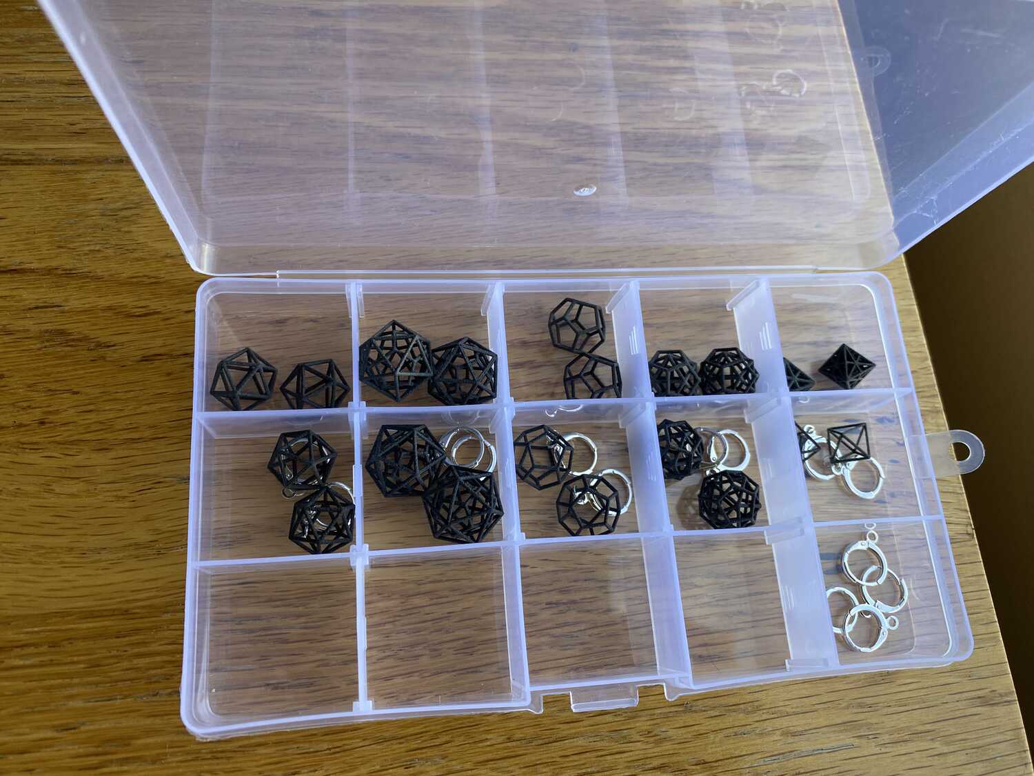
For the types of polyhedra, I already had the icosahedron in mind. I knew that I wanted to learn sls printing and that printing an small scale icosahedron frame would work better with having to risk removing supports. To expand on the icosahedron, I also modeled and printed the other platonic solids: tetrahedron, dedecahedron, octohedron, and some variation of a cube.
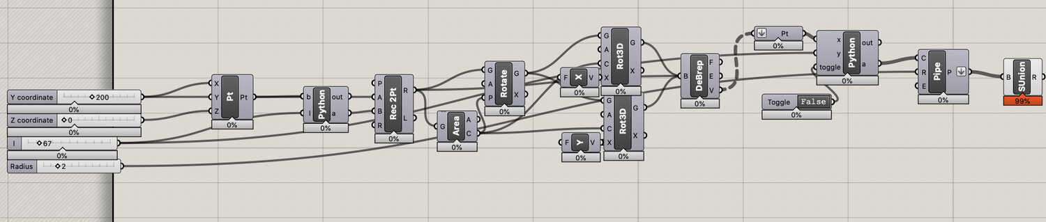
Additionally, I wanted to experiment with filling in the interior verticies using a script in grasshopper so that it would definitely not be easy to do subtractively. For that part of the assignement I ended up creating an icosahedron that could wiggle around in a dodecahedron, as well as the interior icosahedron of a cube that has all of its verticies connected (as well as the mid points):


Part 3: Cading the prototype
First, I make a rough sketch so I know what I'm trying to do: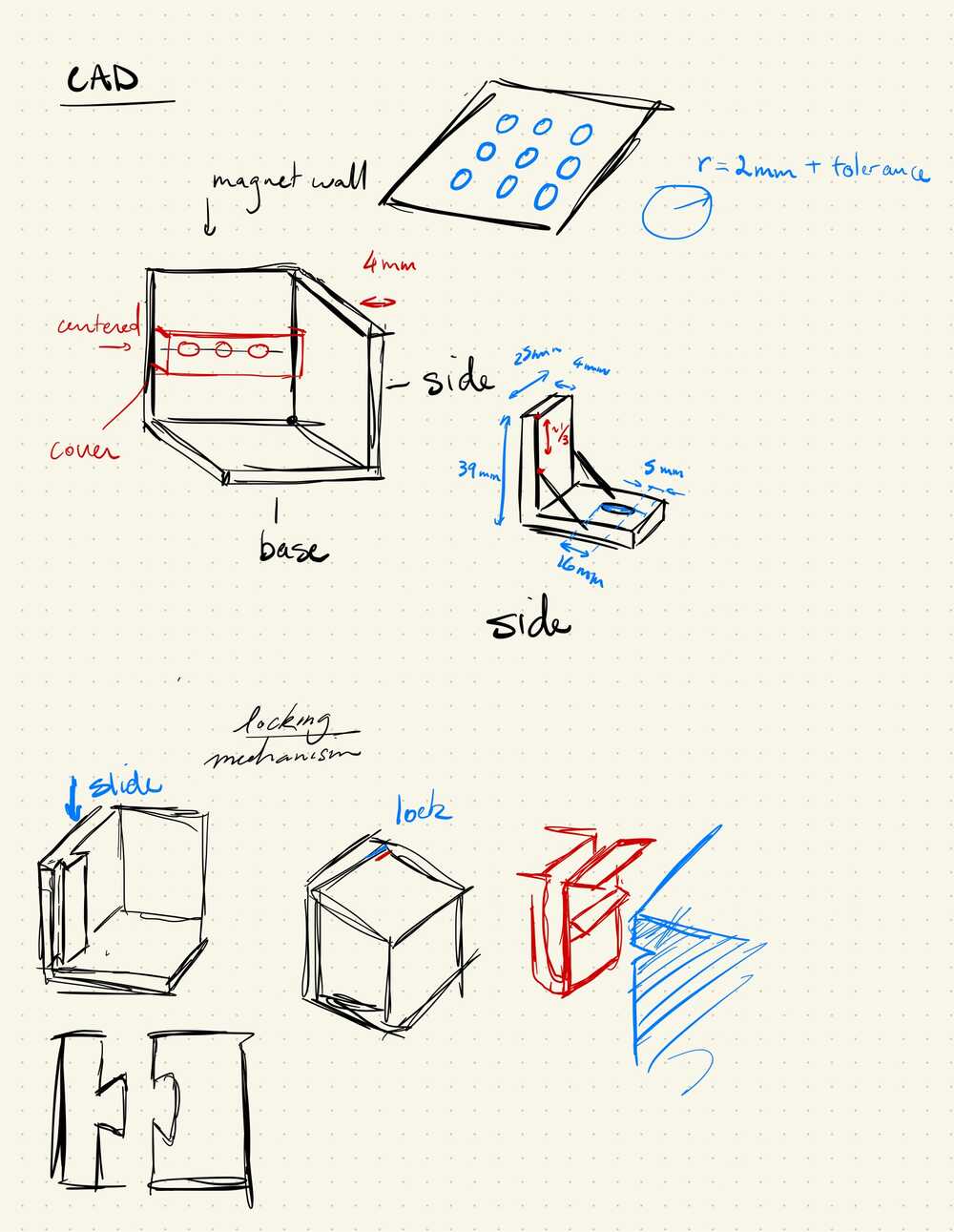
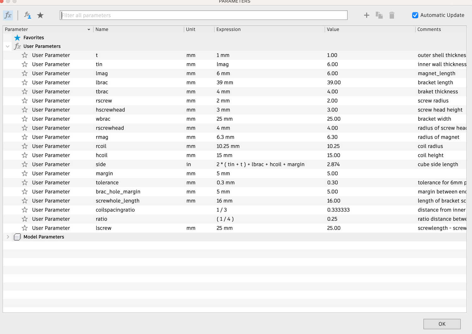
Measuring all the parameters:
These are all the parts that I've been using for my prototype:

Since this CAD process to a lot of trial and error, and finally getting around to following very helpful tutorials (like this series recommended by Alfonso https://www.youtube.com/watch?v=d3qGQ2utl2A) I will try to keep it straightforward. Here is the overall process:
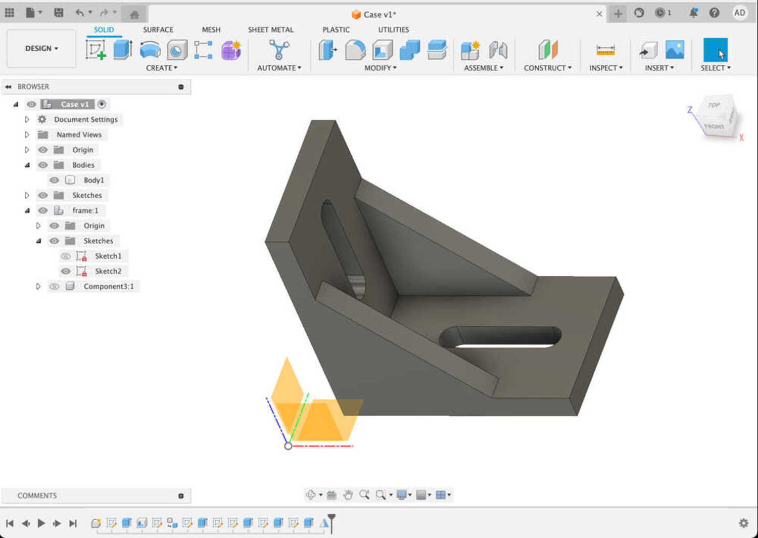
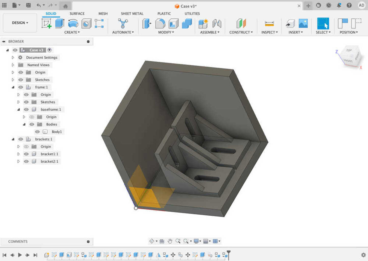
First, I create the component of the frame of my cube.
Then, create the brackets by extruding rectangles and mirroring along the diagonal plane.
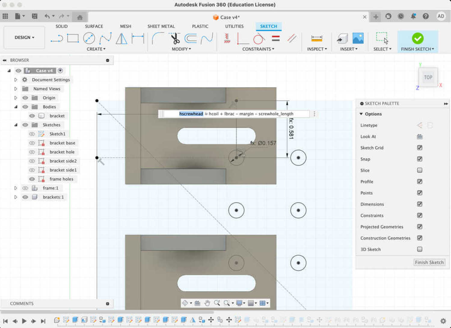
Make the holes using rectangular array and calculating the distances from the edges.
I used something like ratio*(cube_side-2*(outer_thickness+inner_thickness)), with the ratio as 1/4 or 1/3.
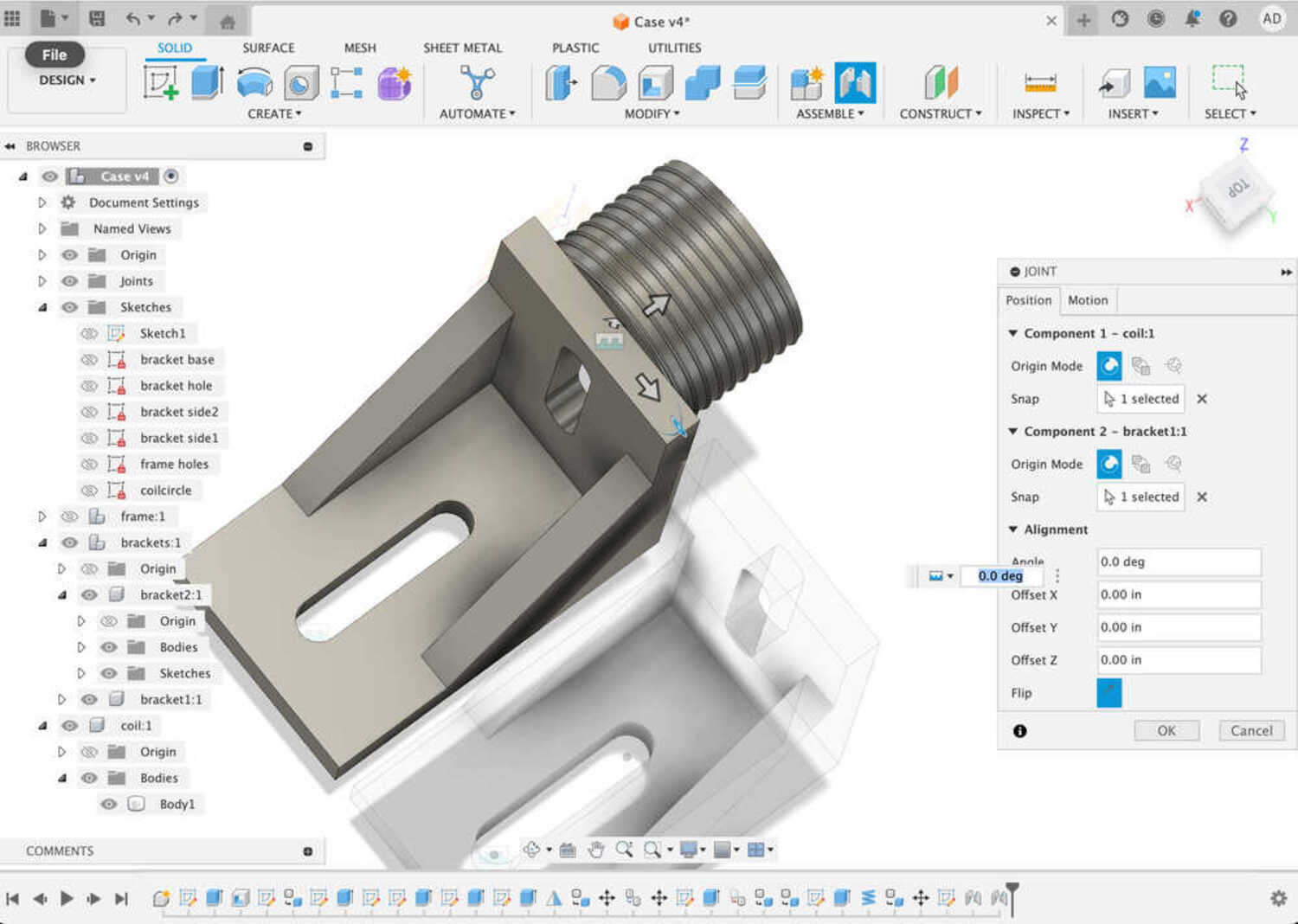
Assemble the brackets with the holes by snapping them.
Create the coils: Create a cylinder and add a tight coil around it with the coil radius and height parameters.
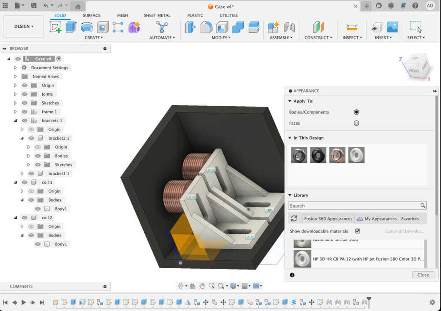
Adding some materials
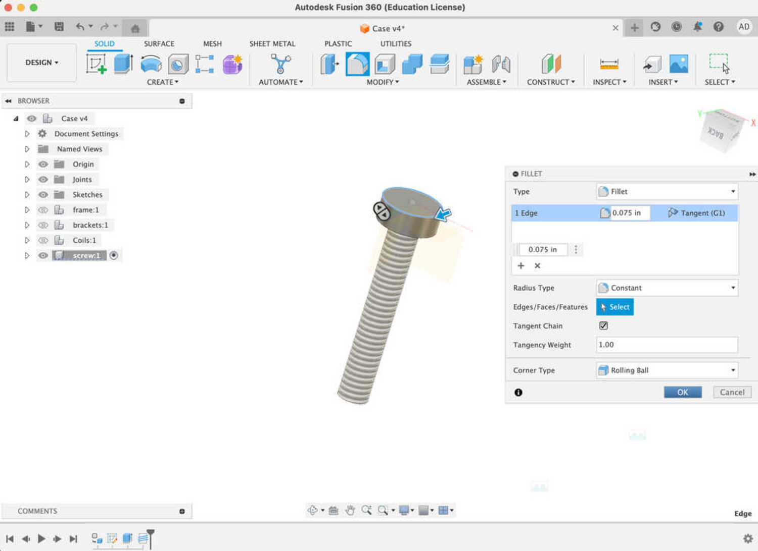
Create the screw by extruding circles
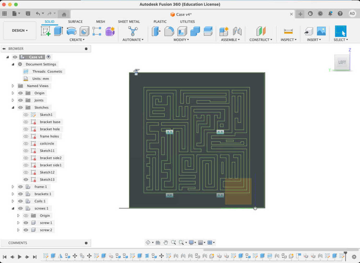
Import the cube design and place on a face of the frame.
Some of the things I had to debug were:
- figuring out how to keep things organzied and compatible with assembly (this is explained very well in the tutorial series).
- finding the right plane for mirroring the brackets (I extruded triangles drawn on the side planes and used those).
- how to move components relative to each other (create joints).
- constraining holes to the middle of a rectangle (create construction lines).
- missalignment, I found a mistake while trying to change a parameter.
It turns out one of the dimension was an aribtrary number instead of a paramenter :/

The final assembly with all the materials is very satifying. I was very impress at how straigthforward things were after figuring out the mechanics.

In the future here are the features I would like to add:
- sliding feature for joining with the second half of the frame
- battery holder
- magnet holders in the wall for the opposing side of the coils
- locking mechanism once the second half slides all the way download
- rp2040 placeholder
(I implement and test some of these during the final week sprint in final projects page)