Final Project - EMH Reader(This page is still under construction)
Introduction
Designing and constructing the Electro-Mech-Hydraulic(EMH) Reader, driven by interest for machinery and its interaction with paper, featuring a versatile robotic arm with hydraulic precision control for tasks including page turning.
TL;DR
Following the requirements and structure of this page https://academy.cba.mit.edu/classes/project_presentation/index.html, I summarize the content of this project as follows:
- Answering
-
What does it do?
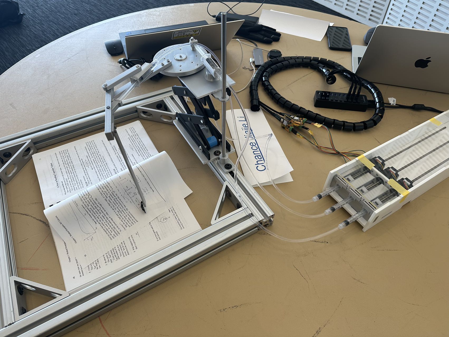
- It is a versatile robotic arm with hydraulic precision control, primarily designed for page turning, but capable of various automation tasks.
-
Who’s done what beforehand?
- Disney Research’s Robotic Manipulator: Disney Research developed a highly responsive robotic manipulator using a hybrid of hydraulic and pneumatic systems, capable of delicate tasks with lifelike motion. Link
- Hydraulic Robotic Arms in Manufacturing: Hydraulic robotic arms are pivotal in manufacturing for tasks like palletizing and welding. These arms are known for their flexibility and efficiency. Link
- Hydrabot: The Modular Electro-Hydraulic Robot Arm: Developed by the University of Waterloo, Hydrabot is a modular and reconfigurable robot arm that uses hydraulic actuators to enhance payload capacity and versatility. Link
- Origami Folding by a Robotic Hand: This study by Kenta Tanaka, Yusuke Kamotani, and Yasuyoshi Yokokohji explores the use of a robotic hand in folding origami, demonstrating advanced capabilities in precise manipulation of paper. Link
-
What did you design?
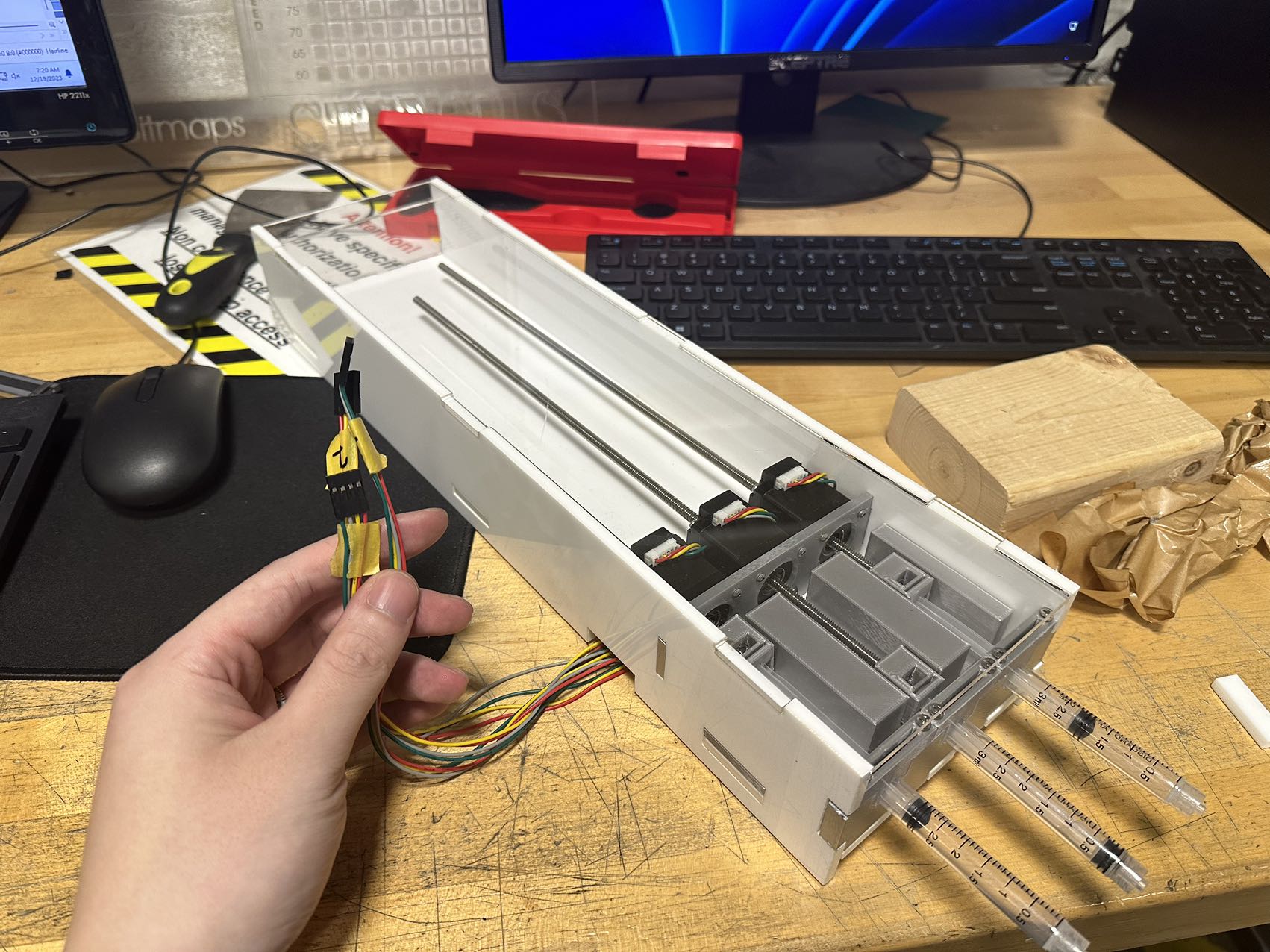
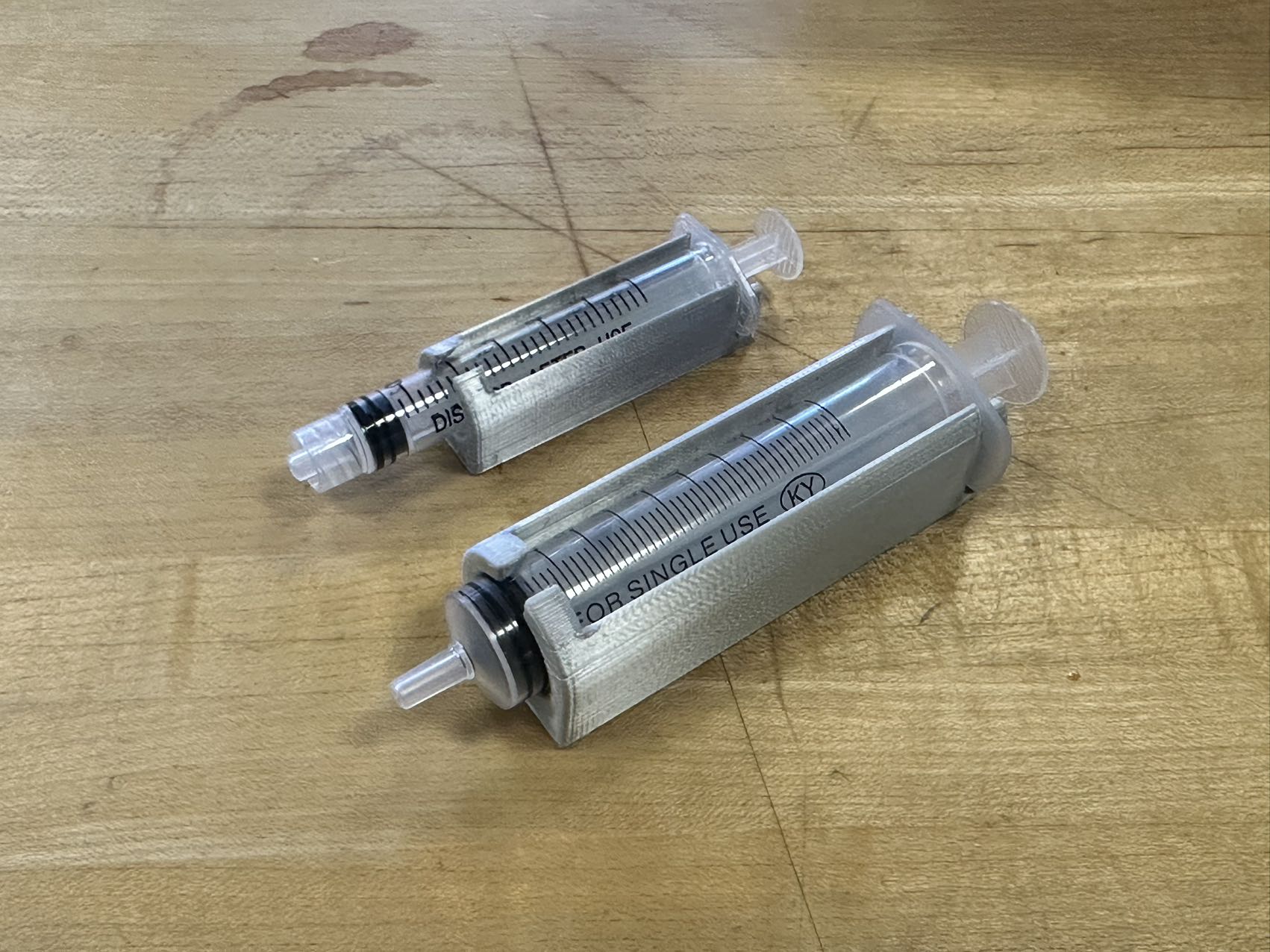
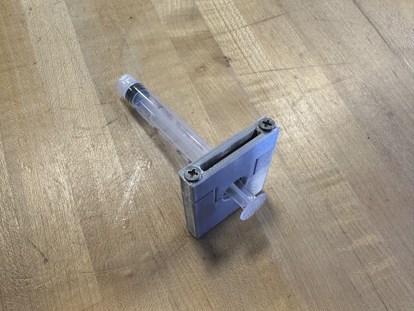
- A 3D-printed and laser-cut acrylic syringe holder to house the hydraulic system.
- A sub-system with stepper motor with a threaded shaft for precise pushing and pulling of the syringe.
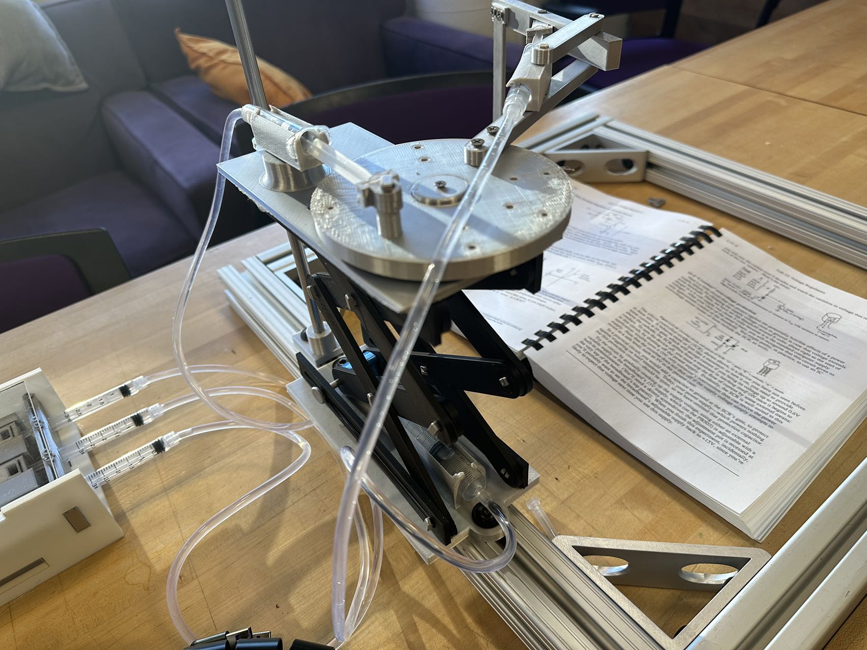
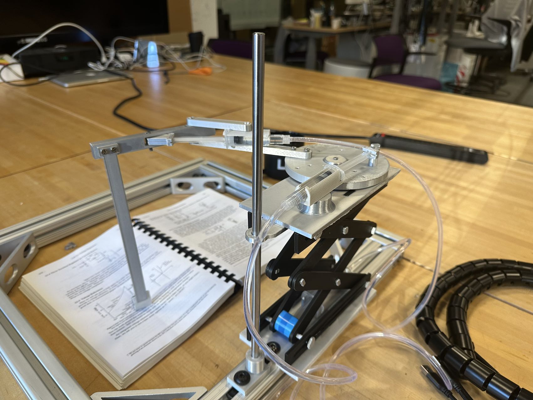
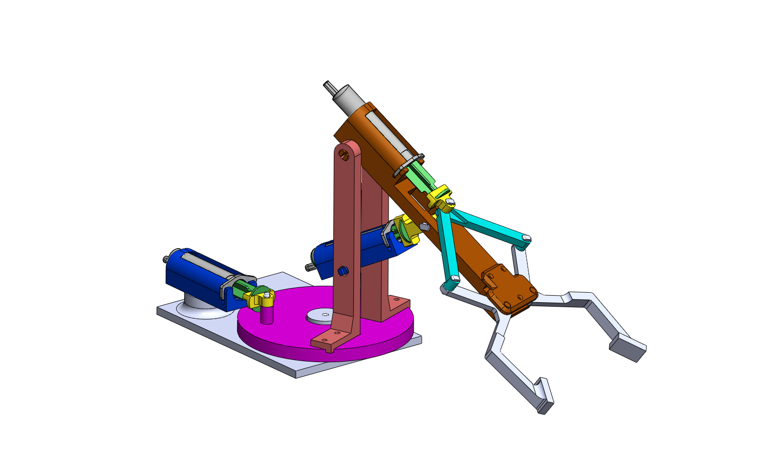
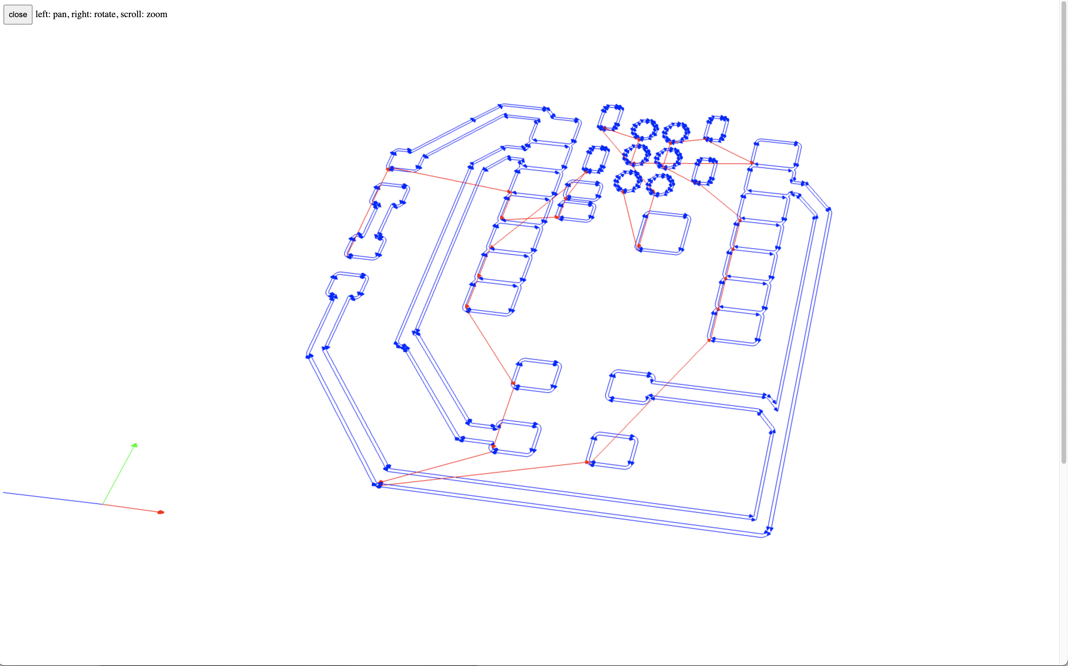
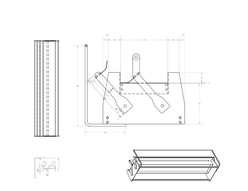
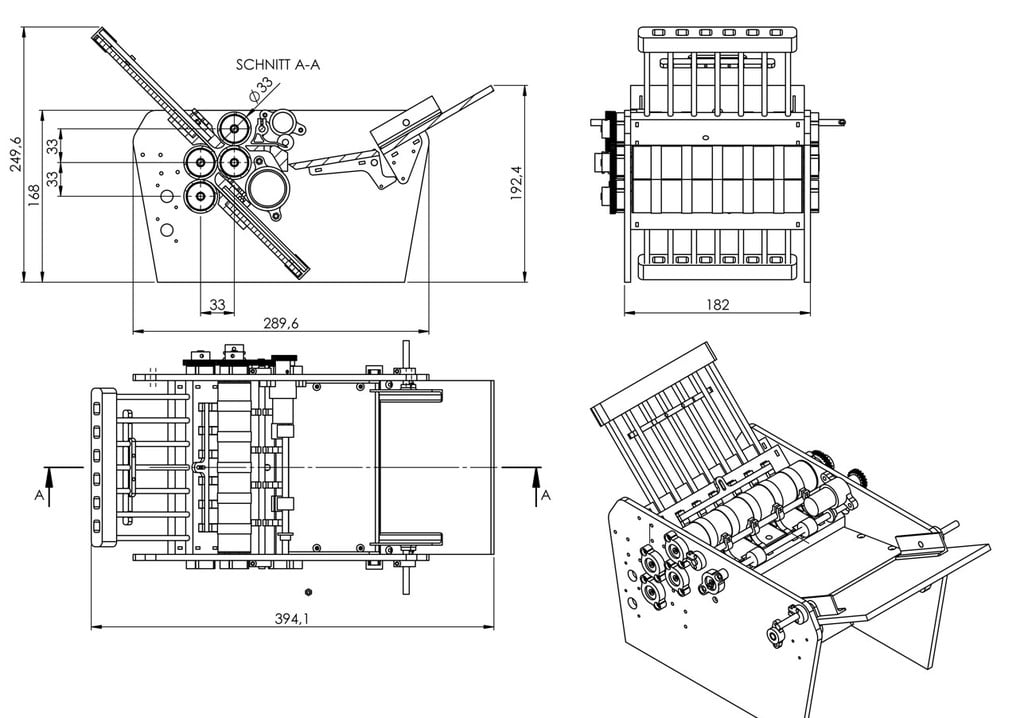
- A 3 Degree of Freedom (3 DoF) robotic arm’s mechanical design, featuring a scissor mechanism for elevation, a disc for lateral movement, and a linkage system for push-pull actions.
- A front-end control panel control the project.
-
What materials and components were used? Where did they come from? How much did they cost?
- it costs ~$89.0 in total
-
Material Unit Price (USD) Quantity Total Cost (USD) Link PLA (3D Printing) 22.06 (per kg) 0.4 kg 8.82 Amazon Acrylic (300 cm²) 7.50 1 7.50 Acme Plastics XIAO ESP32 RP2040 4.99 3 14.97 Seeed Studio Casun HYBRID STEPPING MOTOR 28SHD4102-350TT 4.07 3 12.21 Casun Stepper Motor Tubes 3.50 1 3.50 Online Metals Threaded Shaft 6.50 3 19.50 Online Metals Syringes 0.75 6 4.50 Amazon 2020 Aluminum Extrusion Profile 20mm Linear Rail 1ft 4.50 4 18.00 Amazon
-
What parts and systems were made?
- Mechanical Components:
- Stepper motor with a threaded shaft for precise syringe manipulation.
- 3 DoF robotic arm with a scissor mechanism, lateral movement disc, and a linkage system.
- Hydraulic System:
- Integration of hydraulic components for precise control and power.
- 3D-printed and laser-cut acrylic syringe holder for housing the hydraulic system.
- Front-End Control Panel:
- User interface design for manual control and programming of the robotic arm’s actions.
- Mechanical Components:
-
What processes were used?
- system integration and packaging
- embedded microcontroller design, interfacing, and programming
- front-end control panel
- remote controller
- stepper motor controller
- modular things debugging, fixing and customization
- electronics design and production
- remote controller
- stepper motor controller
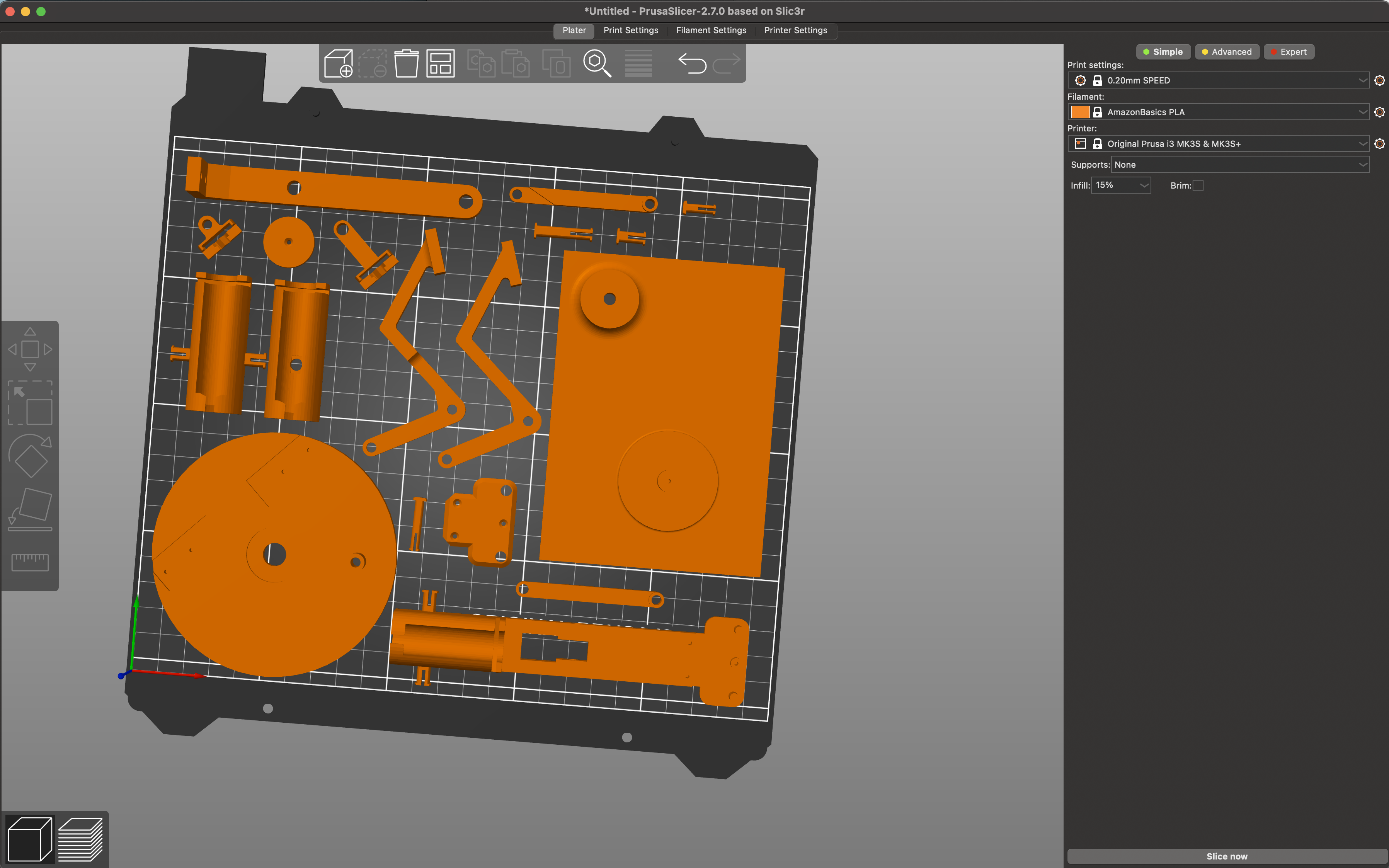
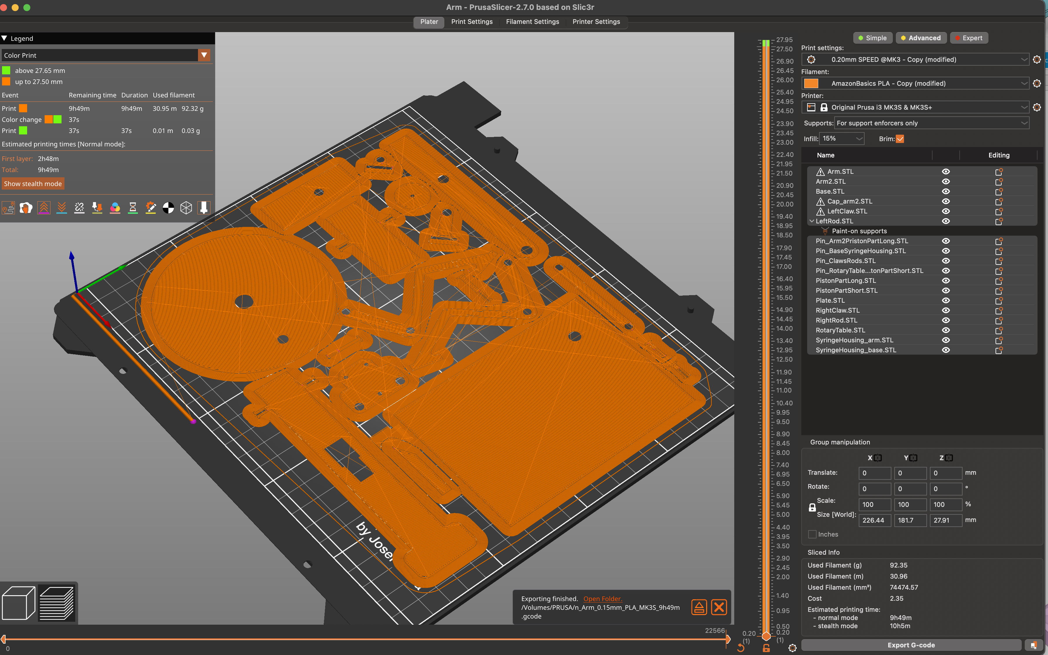
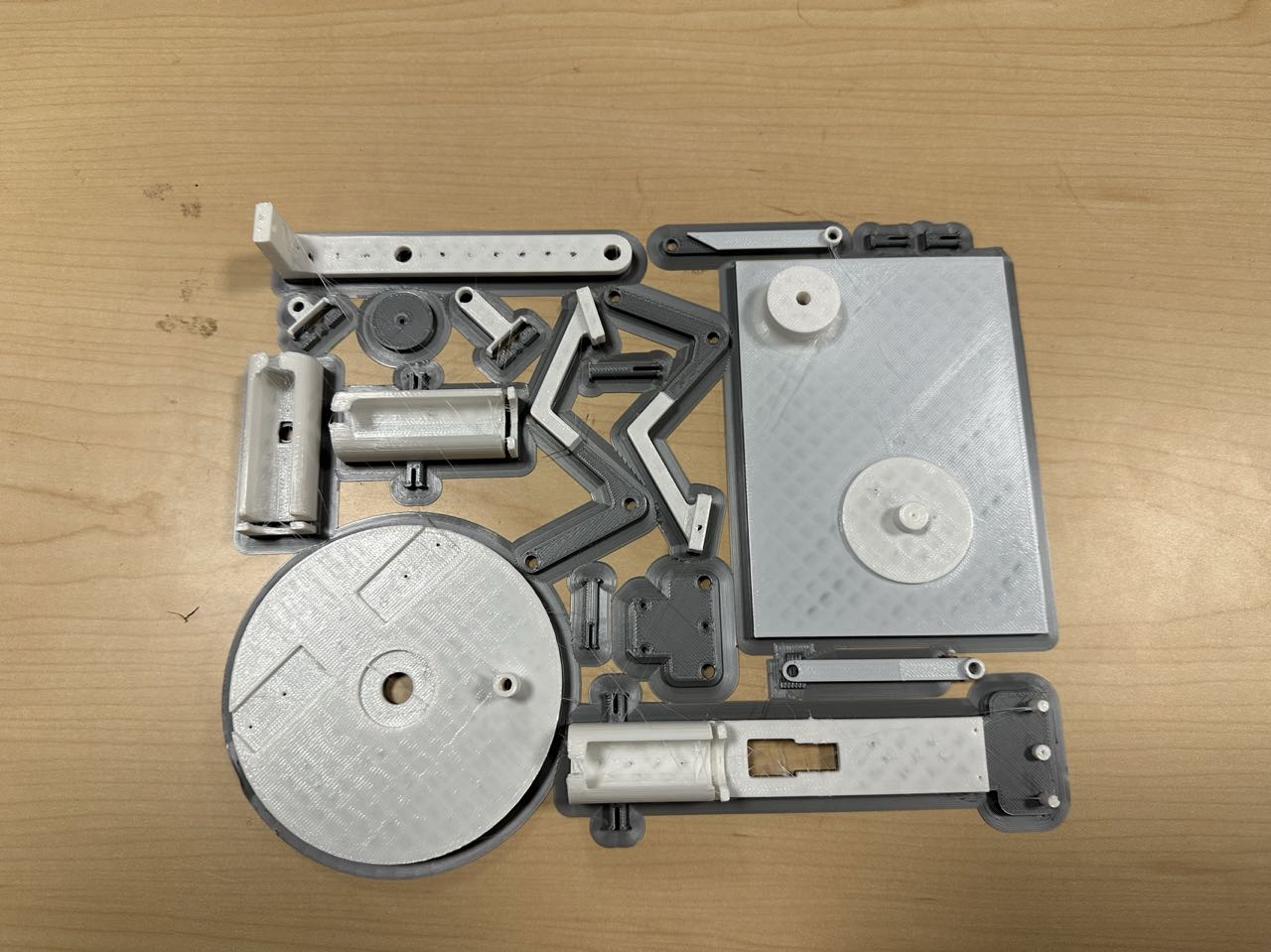
- additive fabrication processes / 3D design
- 3D printing all components in robotic arm
- Elevator Scissors: Mechanism for vertical movement, possibly using a scissor lift design.
- Slides of Arms, Upper/Lower/Middle Arm Components: Components comprising the sliding sections of the robotic arms, including upper, lower, and middle arm segments.
- Pan Rotating Structure: Rotational mechanism for panning or horizontal movement.
- Arm Holding Platform: Platform for securing and holding the robotic arm.
- Pins Connecting the Joints and Components: Fasteners used to connect and secure joints and components.
- Rod to Actuate the Elevator: Rod used for elevating or lifting components, likely part of the scissor lift mechanism.
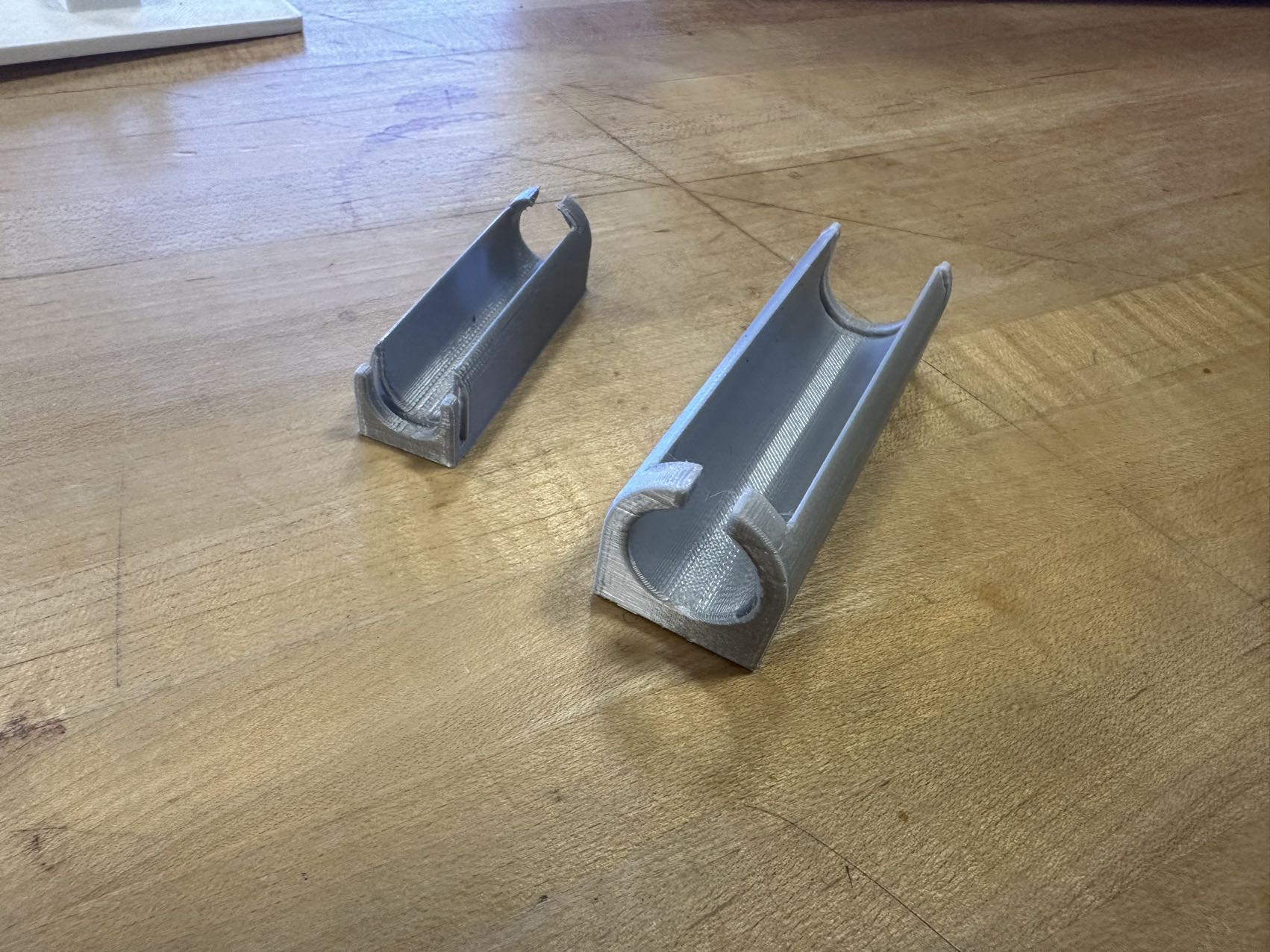
- Locks for Different Syringes’ Handle: Locking mechanisms designed for various syringe handles.
- Holder for Different Syringes: Device used to hold and secure different types of syringes.
- Lock for Threaded Shaft: Locking mechanism for the threaded shaft to prevent movement.
- Guide Rail Fixtures: Mechanical fixtures used to secure and guide rails, likely part of the frame and structural components.
- 3D printing all components in robotic arm
- Holder for the Driving-Side Syringe: A component designed to secure and control the syringe on the driving side of the system.
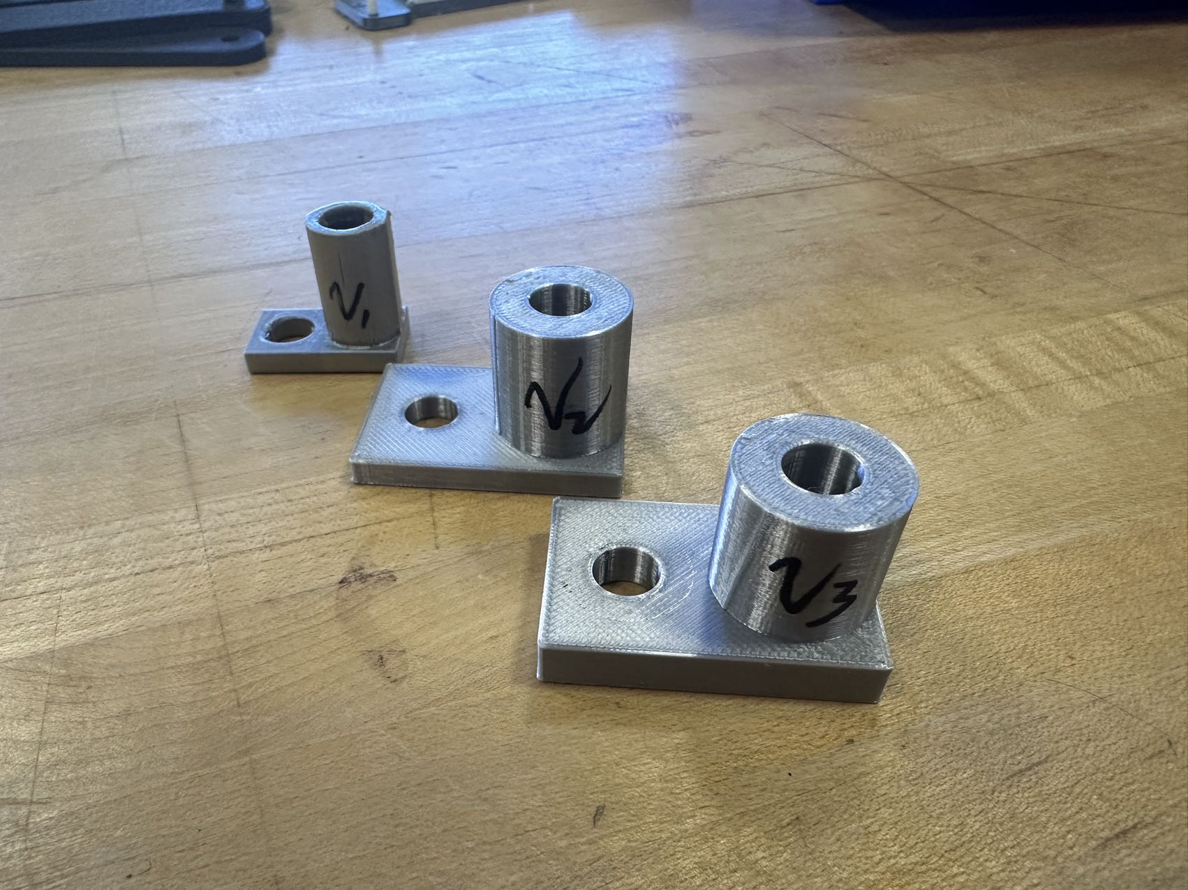
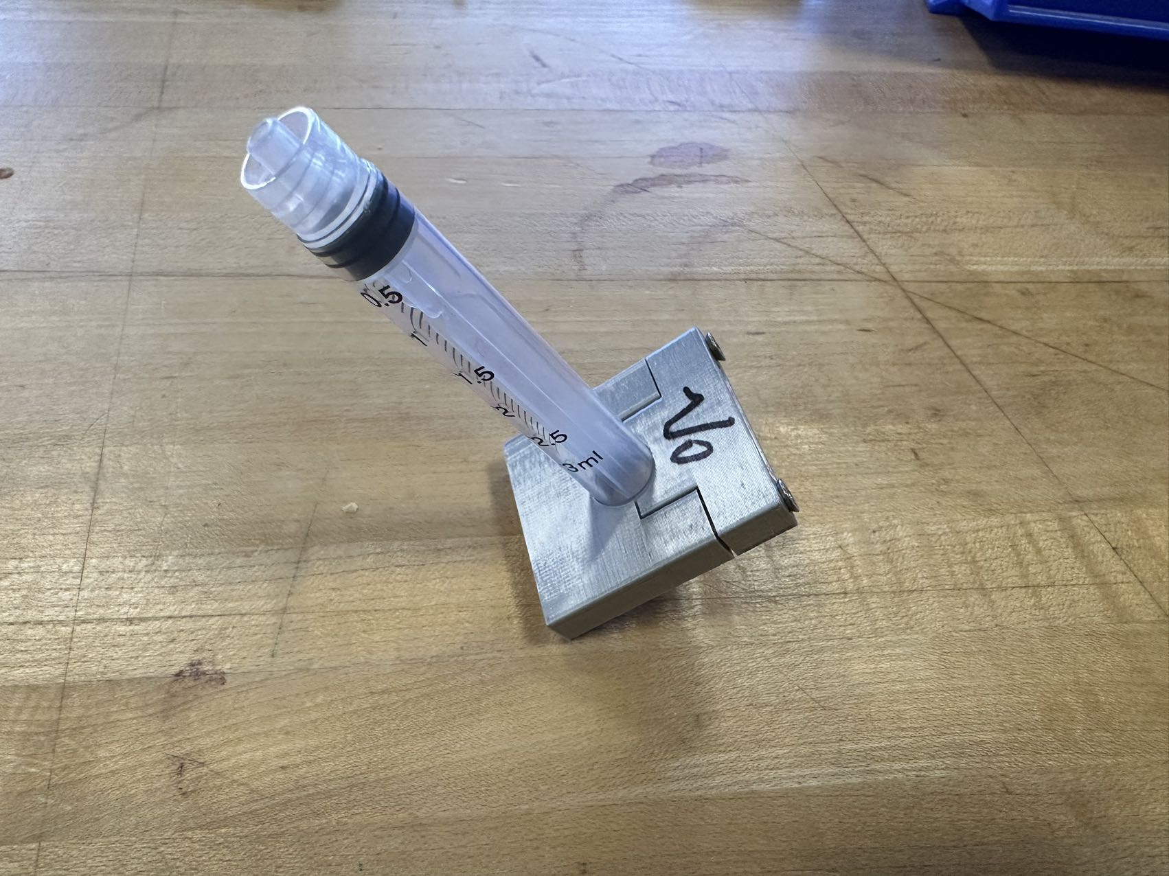
- Holder for the Stepper Motor: A fixture designed to secure and position the stepper motor, which is responsible for controlling various movements.
- Guide for Threaded Shaft (Preventing from Self-Rotating): A guide mechanism that prevents the threaded shaft from rotating on its own.
- 3D printing all components in robotic arm
- subtractive fabrication processes / 2D design
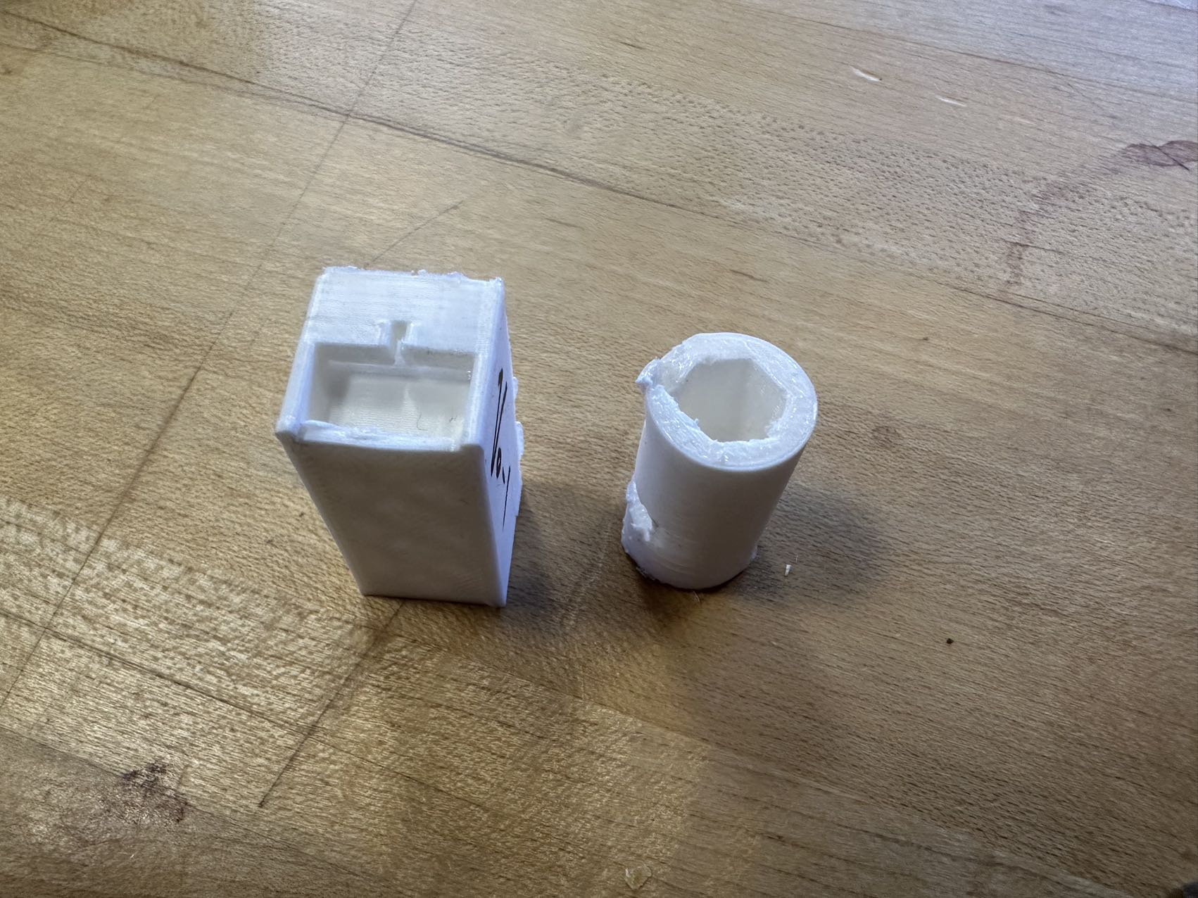
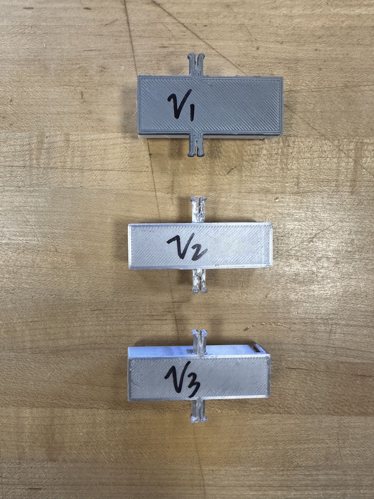
- Driving-Side Enclosure: An enclosure or box on the driving side of the system, serving both aesthetic and hydraulic pressure conduction functions.
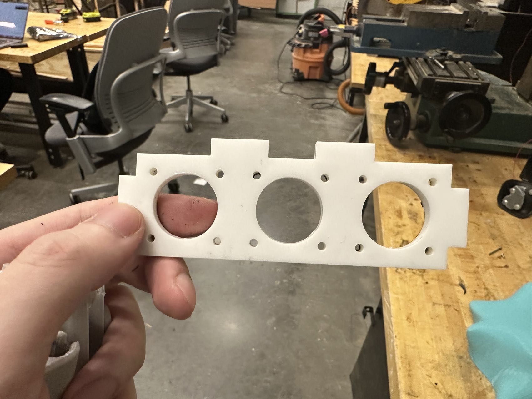
- Upgraded Holder for the Stepper Motor: An improved fixture designed to secure and position the stepper motor, addressing the issue of melting associated with the previous 3D-printed version when the motor heats up.
-
What questions were answered?
- How can an electronic hydraulic arm system be constructed at a low cost?
- How can hydraulic, electrical, and mechanical elements be combined to accomplish tasks within complex systems?
-
What worked? What didn’t?
- What worked:
- The design and construction of the EMH robotic arm with hydraulic precision control.
- Integration of mechanical, hydraulic, and electronic systems.
- Development of a user-friendly control interface for manual and programmed actions.
- What didn’t:
- The control algorithm has not been written yet, and the current control relies on pre-defined rules (due to limited resources in this personal project). In the future, collaboration can be considered to enhance the system’s ability for better generalization.
- What worked:
-
How was it evaluated?
- In a nutshell, the primary evaluation goal was to create a functional demo to verify the end-to-end success of page turning. This means that by pressing a button on a webpage, the mechanical arm successfully turns a physical book page, serving as a proof of concept.
-
What are the implications?
- Cost-Effective Automation: By leveraging hydraulic flexibility to enhance force output within a constrained budget(<$100), the project demonstrates a practical approach to achieving robust automation in economically limited environments.
-
Conception
As someone with a longstanding fascination for the interplay between machines, paper, and their intricate interactions, this project represents a passionate endeavor to explore the creative possibilities at this intersection.
In the realm of machine building, the project’s central objective is to maximize the potential of hydraulic technology. It aims to construct a highly cost-effective and extraordinarily versatile machine. This approach allows for a comprehensive exploration of hydraulic systems, emphasizing their role in achieving intricate movements and precise control. The core application of this machine lies in enhancing paper-related tasks, including page-turning and paper folding, while emphasizing the synergy between machine building and hydraulic technology for efficient and innovative solutions.

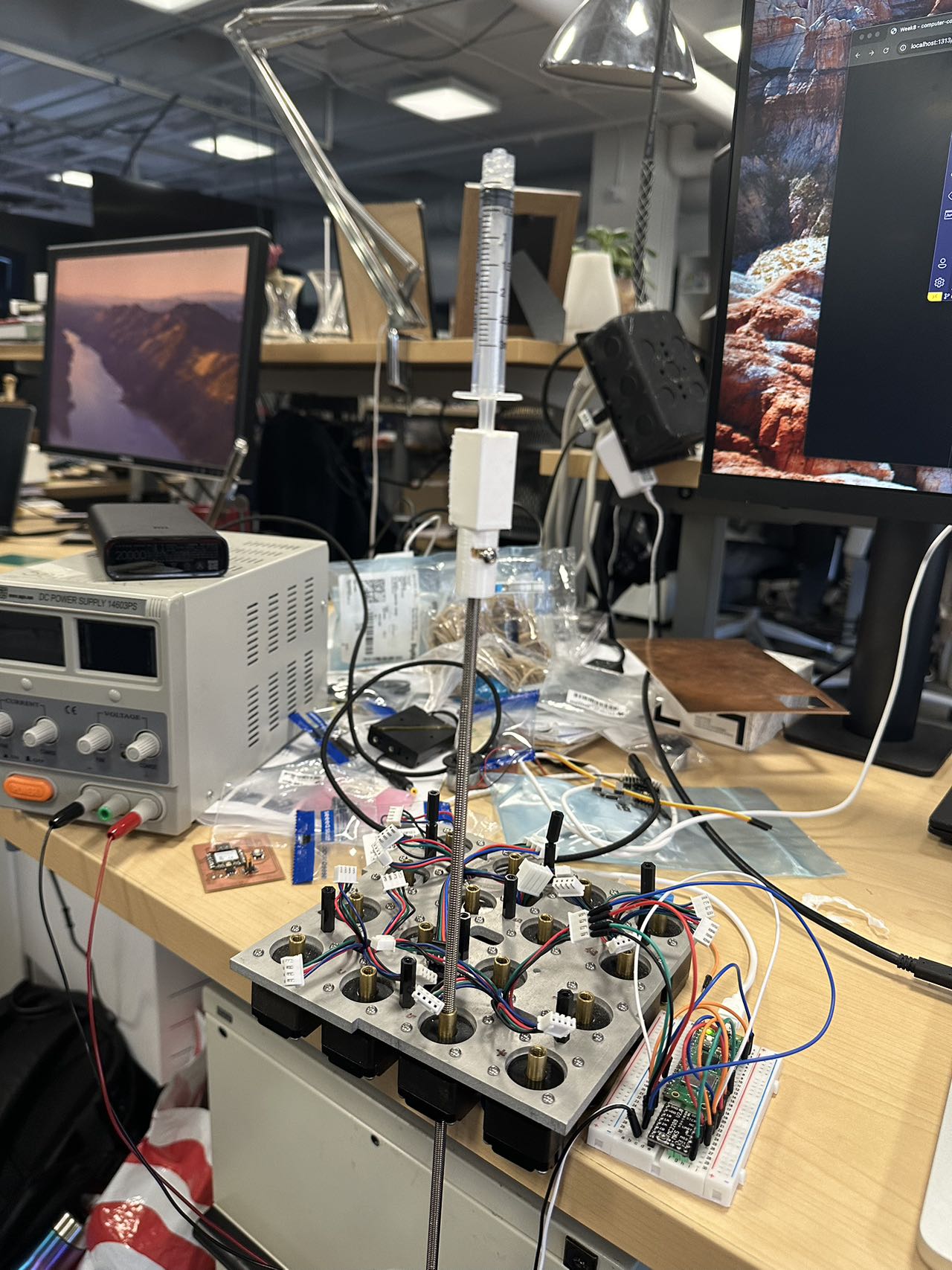
System Integration
The final project was a test and challenge of system integration. Neil repeatedly emphasized the principles of 80/20 and 95/5, which indeed manifested when I started working hands-on. Fortunately, I was able to successfully resolve all the issues and achieved a stable live demo effect on the open day. Here, I’ll detail the three most memorable challenges I encountered during the system integration process.
The hot stepper motor softened the support structure of the 3D print
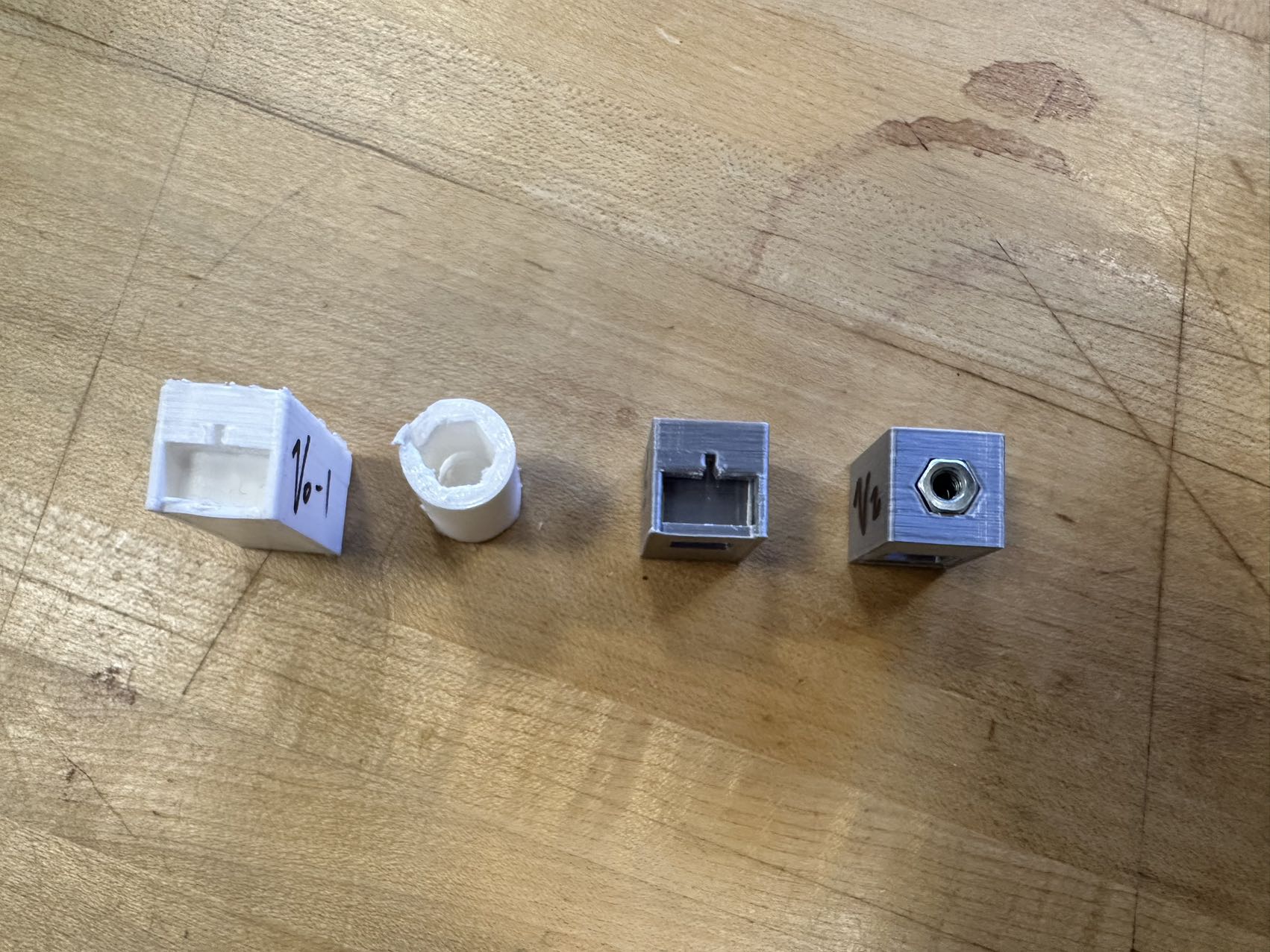
The issue arose when the high-torque stepper motor generated excessive heat, causing the 3D-printed support structure to soften unexpectedly. Initially, I had printed three motor mounts using PLA (Polylactic Acid), and the measurements and strength seemed adequate during pre-testing. However, once the motors were in actual operation, they emitted a significant amount of heat, which rendered the PLA support ineffective. This challenge only became evident after system integration.
In response to this setback, I promptly fabricated a new motor mount using acrylic material. Additionally, I adjusted the thickness of the support structure, increasing it from 4mm to 6mm. These modifications provided a more stable and robust support system, effectively addressing the heat-related softening issue.
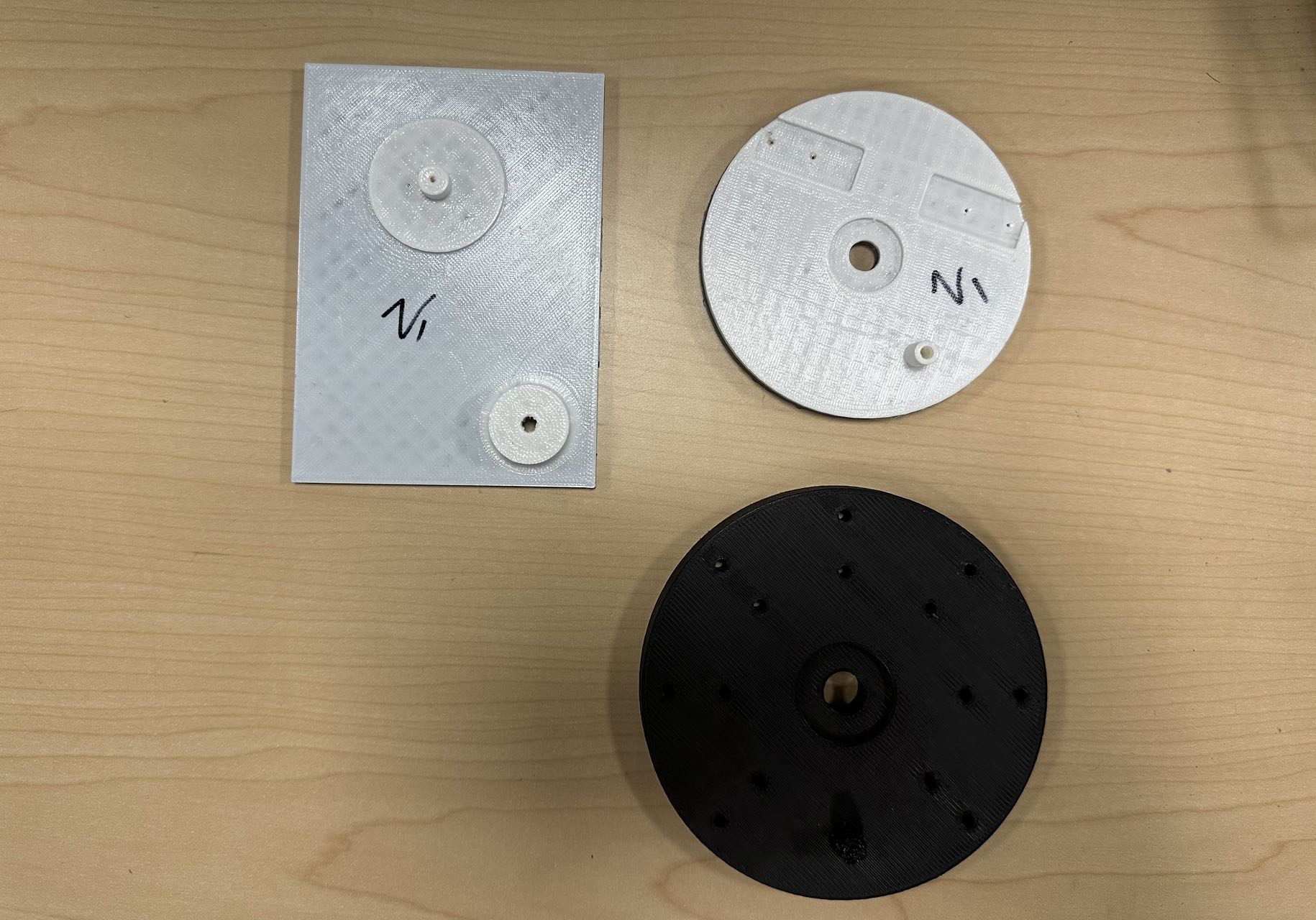
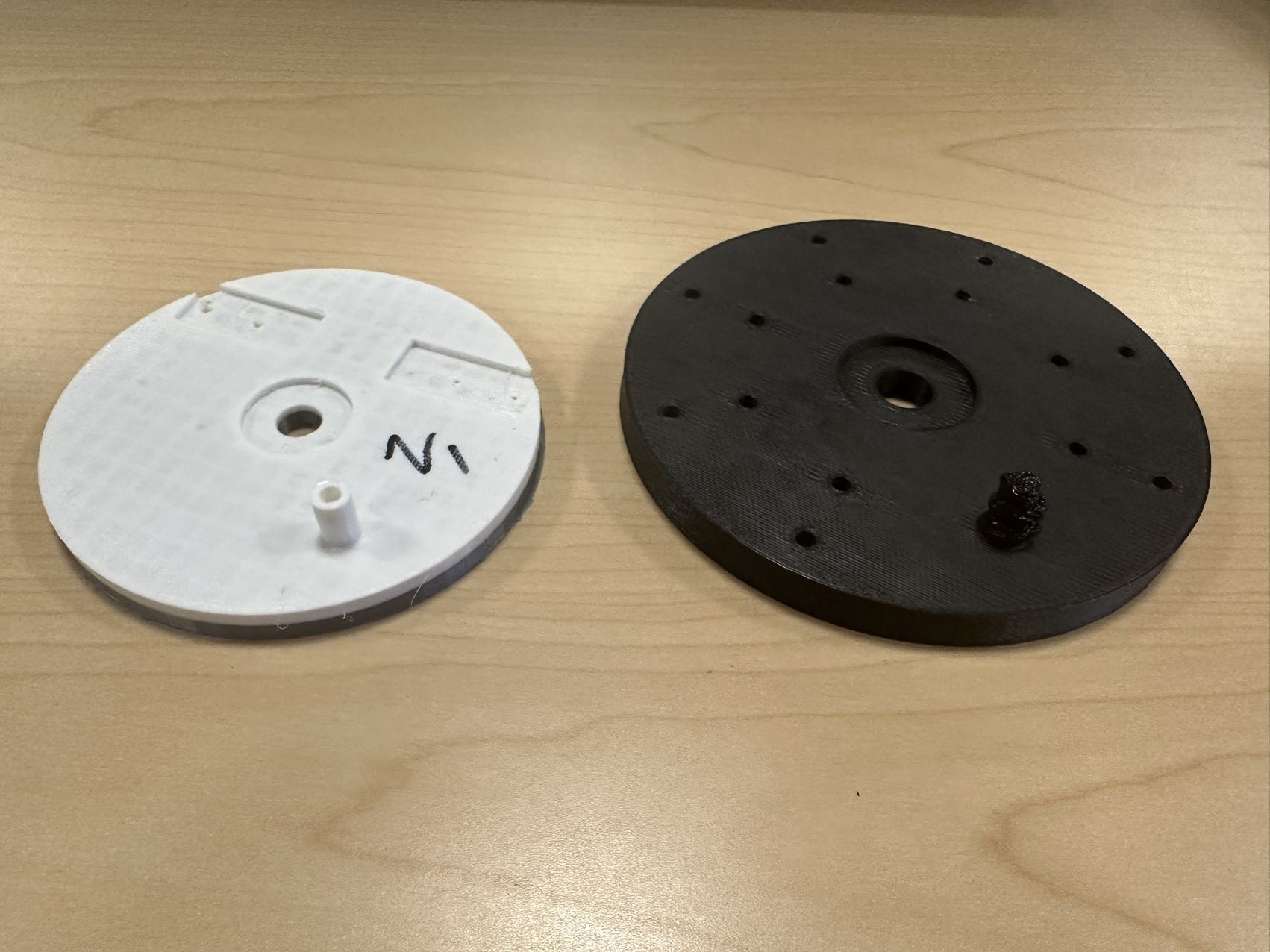
The weight of the mechanical platform was too heavy for ordinary syringes to support.
Before attaching all the arms to the mechanical platform, the hydraulic system operated smoothly. However, when it came time to support the full weight of the arms, the hydraulic needle at the elevator couldn’t handle the load, resulting in a vacuum effect when attempting to move it. In response, I promptly 3D-printed a new base and replaced the hydraulic needle with a larger one. This adjustment was made to leverage hydraulic principles and provide the necessary additional pressure to support the increased weight effectively.


The drive-side bracket, for aesthetic reasons, did not have enough support structures printed.
During the development of the project, I encountered a unique challenge related to the drive-side bracket. This component, which was crucial for the overall stability and performance of the machine, had an interesting twist due to aesthetic considerations. I wanted the design to be sleek and visually appealing, so I initially didn’t include as many support structures as I should have.
As I conducted various tests, one particular incident stood out. Thankfully, my lab mate happened to record it on video, providing valuable insights. In the video, which you can observe in the lower-right corner, I was conducting tests to check the performance of each individual hydraulic needle when pushing. To my surprise, when I tested each needle separately, the structure remained stable and performed as expected.
However, the real challenge arose when I attempted to operate all three hydraulic needles simultaneously. As the needles pushed together, I noticed that the front needle panel began to protrude outward, causing the entire mechanism to become unstable and ultimately leading to a failure in the system’s operation.
Upon closer examination and analysis of the situation, I identified the root cause of this issue. The problem stemmed from the initial design of the box housing the needles. In my pursuit of aesthetics and a clean, minimalist look, I had inadvertently made a design mistake. The front end of the box had been designed flat, lacking the necessary rearward constraints for the foremost fingers. This design flaw became apparent when multiple needles exerted pressure together, leading to the instability in the drive-side bracket.
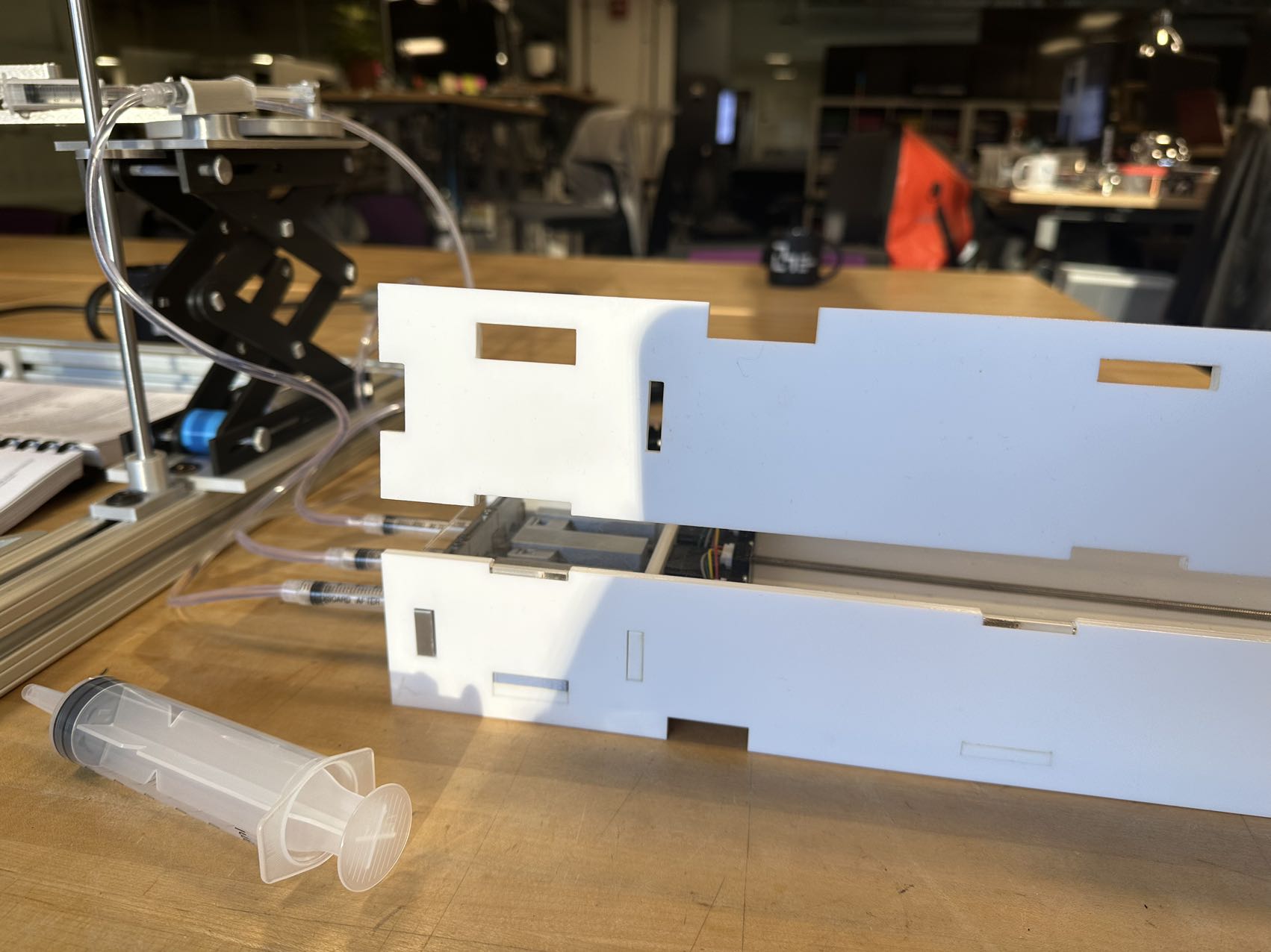
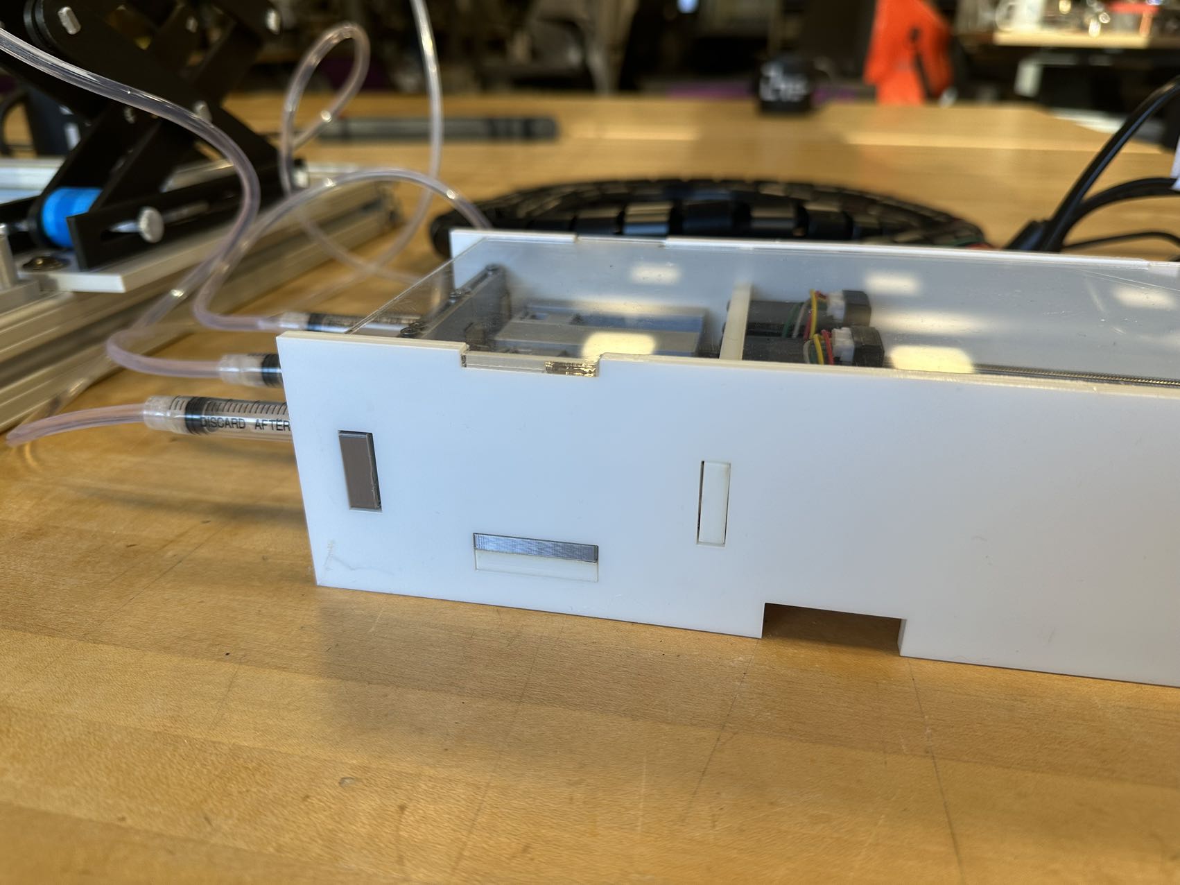
To address this challenge and rectify the issue, I promptly embarked on a redesign of the box housing. I incorporated the much-needed rearward constraints to ensure that the needles remained properly aligned and supported, even when operated simultaneously. After implementing these modifications, the machine’s stability and performance improved significantly, allowing for successful operation and achieving the desired functionality. This experience underscored the importance of a well-thought-out design in the success of the project, and it served as a valuable lesson in balancing aesthetics with structural integrity in engineering projects.
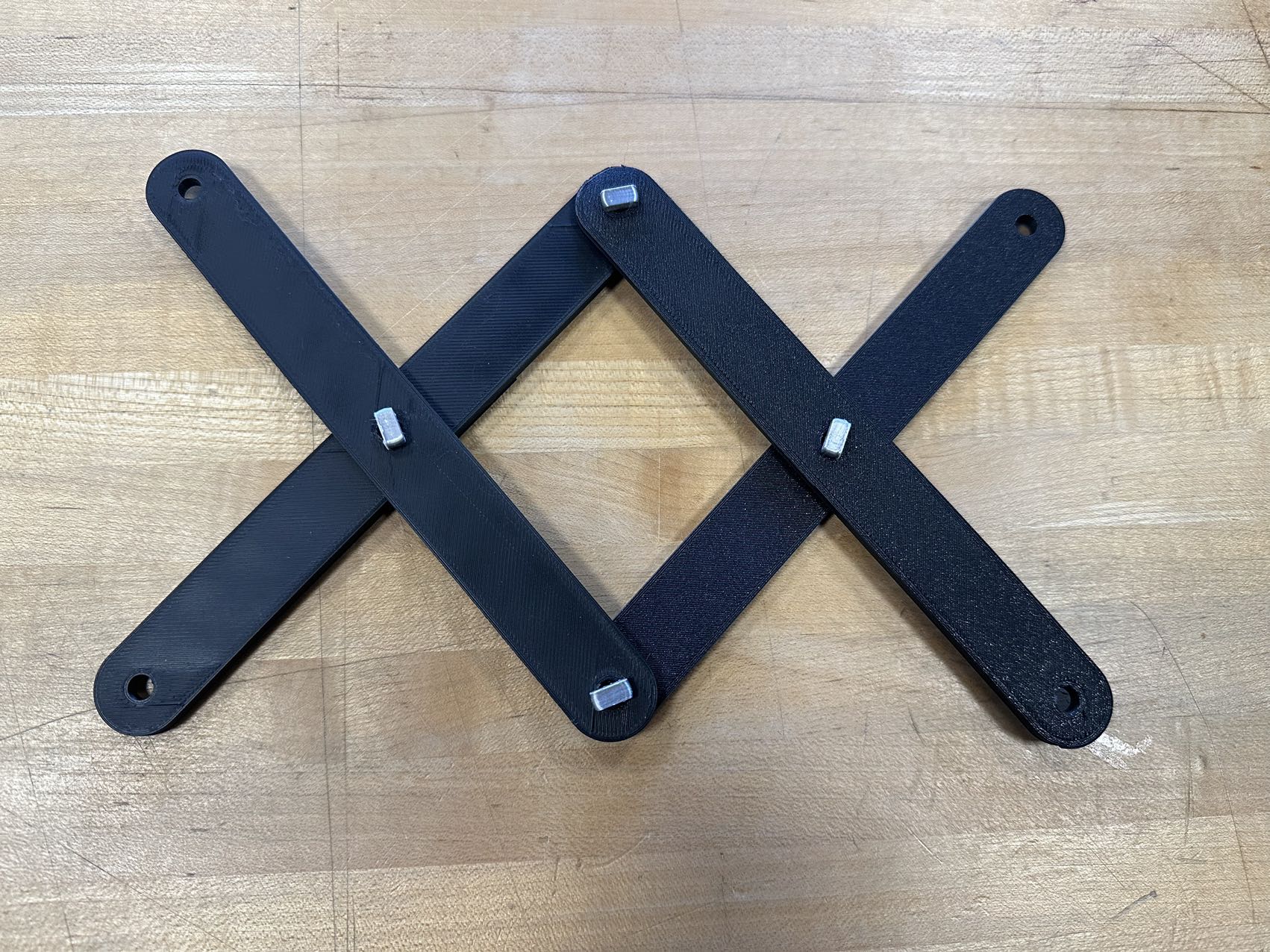
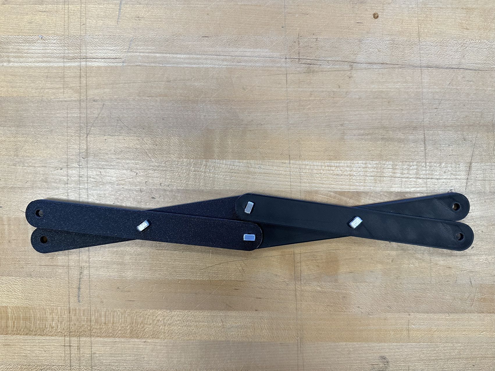
The upper platform tilted outward due to an off-center center of gravity.
The story unfolds with an unexpected challenge: the upper platform’s pronounced tilt towards the outer edge. This tilt occurred primarily because the upper arms of the scissor mechanism were positioned too far outward. As a result, the elevator structure lacked adequate constraints to prevent significant leaning.
Realizing the gravity of this issue, I set out to find a solution that would restore balance and stability to the system. To achieve this, I decided to design and implement a support mechanism using a steel column. This column would act as a critical auxiliary support to counteract the undesired tilt.
In my design process, I carefully created a fixed interface that seamlessly integrated the steel column with both the upper platform and the lower framework. This interface ensured that the support structure remained securely in place, effectively preventing any further leaning or tilting of the upper platform.
This solution not only addressed the challenge but also highlighted the importance of structural integrity and precise engineering in achieving a stable and functional machine. The addition of the steel column provided the necessary support to maintain the desired equilibrium, ultimately contributing to the success of the project.
Construction(progress tracking)
Mechanical Part
1st Spiral


2nd Spiral


Electrical Part
1st Spiral - TMC2209
- SpeedyStepper.h
- software serial
- example code in TMC2209.h repo

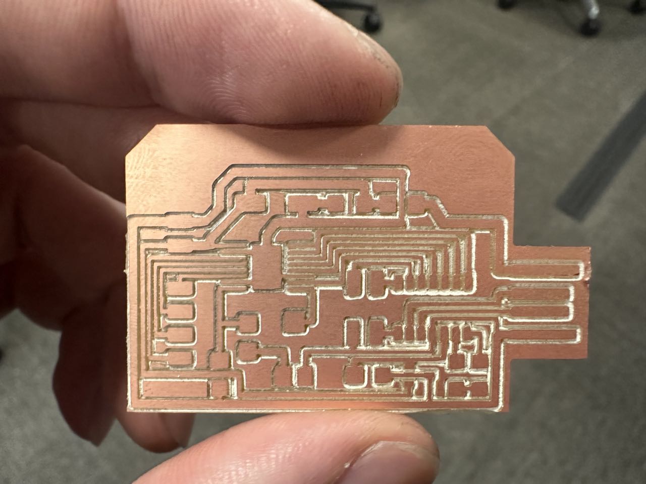
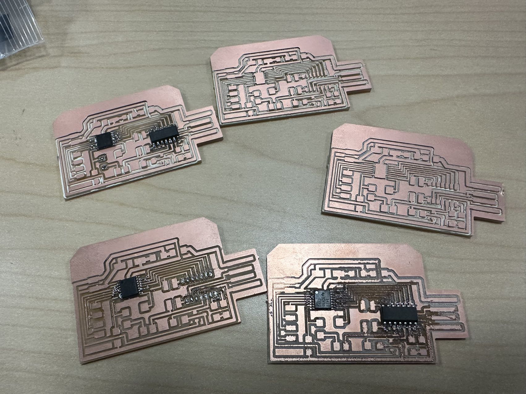
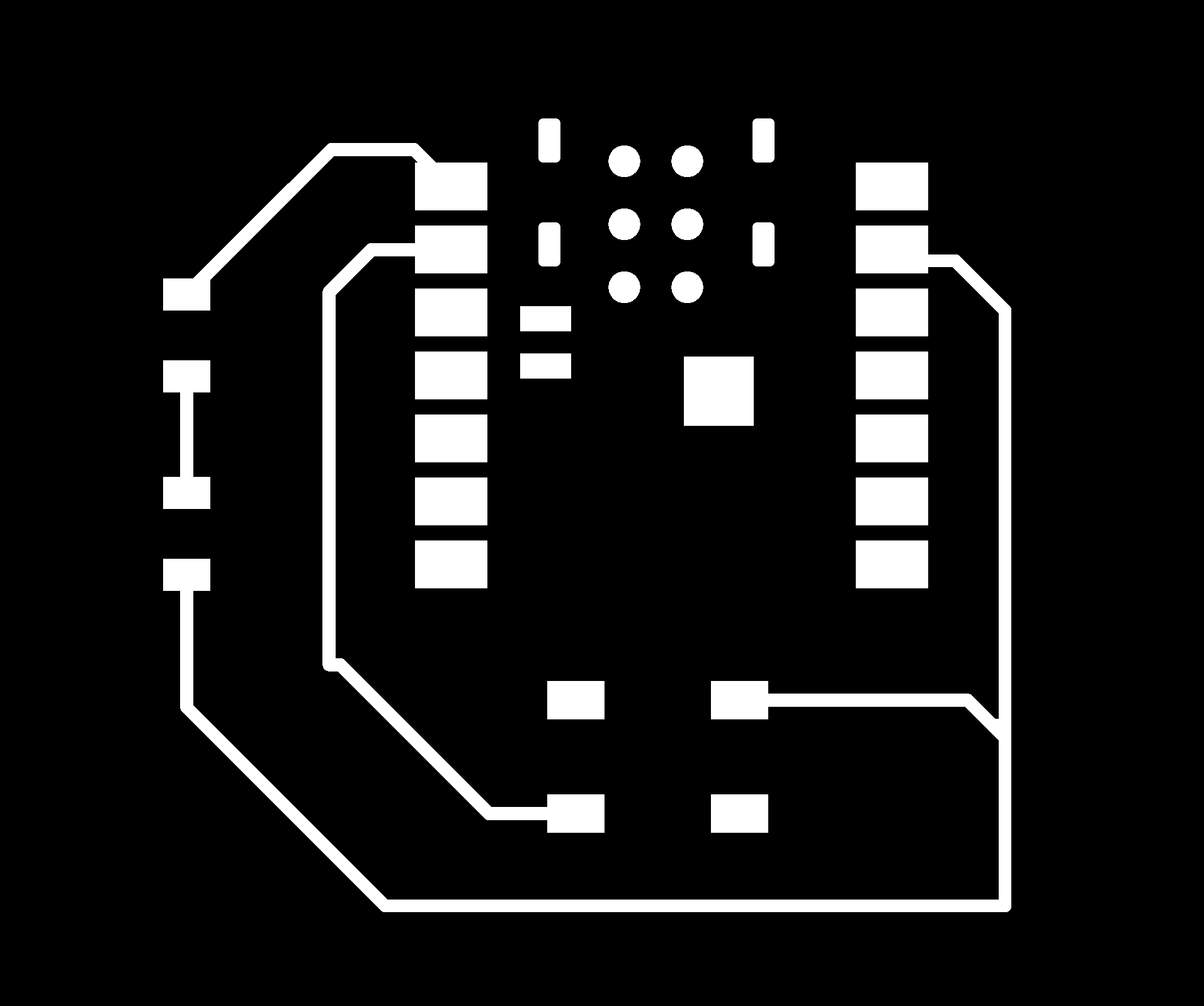
2nd Spiral - DRV8428
this is what I want to reproduce


3rd Spiral


- code for remote control
#include <WiFi.h>
#include <ArduinoWebSocket.h>

const char* ssid = "YourWiFiNetworkName"; // Your WiFi network name
const char* password = "YourWiFiPassword"; // Your WiFi password

const char* serverAddress = "YourServerIPAddress"; // WebSocket server address
const int serverPort = YourServerPort; // WebSocket server port
const char* webSocketPath = "/YourWebSocketPath"; // WebSocket path

const int buttonPin = 2; // Button connected to GPIO 2
bool buttonState = false;
bool lastButtonState = false;

WiFiClient wifiClient;
WebSocketClient webSocketClient;

void setup() {
  Serial.begin(115200);

  // Connect to WiFi
  WiFi.begin(ssid, password);
  while (WiFi.status() != WL_CONNECTED) {
    delay(1000);
    Serial.println("Connecting to WiFi...");
  }
  Serial.println("Connected to WiFi");

  // Initialize the button
  pinMode(buttonPin, INPUT);

  // Connect to the WebSocket server
  if (webSocketClient.connect(wifiClient, serverAddress, serverPort, webSocketPath)) {
    Serial.println("Connected to WebSocket server");
  } else {
    Serial.println("Failed to connect to WebSocket server");
  }
}

void loop() {
  // Read the button state
  buttonState = digitalRead(buttonPin);

  // Send a command to the server when the button changes from pressed to released
  if (buttonState == LOW && lastButtonState == HIGH) {
    Serial.println("Button pressed, sending command to server");
    webSocketClient.send("demo");
  }

  lastButtonState = buttonState;

  // Handle WebSocket messages
  webSocketClient.poll();

  // Perform other tasks here
}
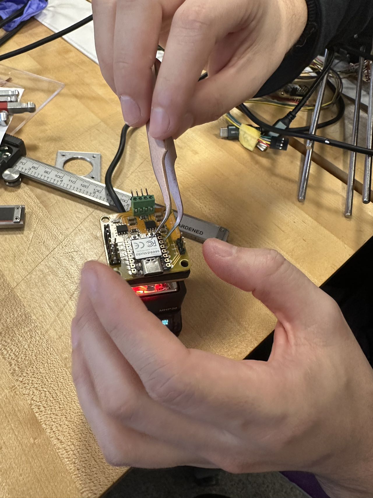
Stepper-hbridge-xiao - https://modular-things.github.io/modular-things/things/stepper-hbridge-xiao/

fixed(resolder+reflash firmware) a few modular things, and then they work
Interface Part
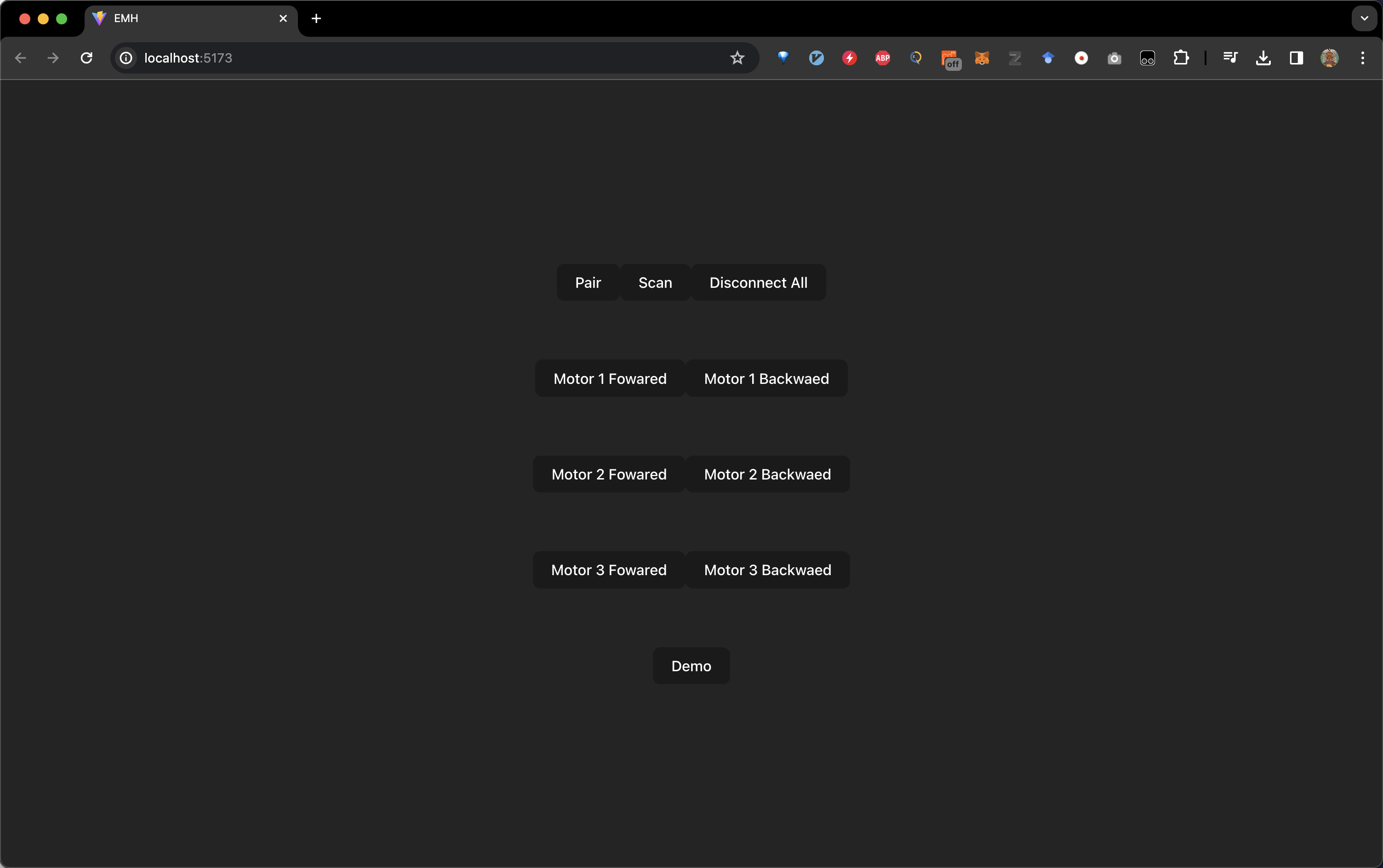
I have built a minimalistic frontend website using React.js, TypeScript, and Vite. This website serves as a control interface for various functionalities related to modular devices. It includes features like scanning for devices, pairing them, disconnecting, individual motor calibration, and a control panel to showcase demos.
For the development related to modular devices, I based my work on Jake’s repository, which can be found at https://github.com/modular-things/modular-things-standalone.
Regarding control, I have established a connection using sockets between the XIAO ESP32C3 and a button on a previous mill setup. This connection allows the machine to turn a page in a book when the button is pressed.
- main page code
import "./App.css";
import { Things, Node } from "./interfaces";

// bring in the things,
import * as mt from "./modular-things/modular-things";
import "./modular-things/things/index";
import { useState } from "react";

function App() {
  const [ globalThings, setGlobalThings ] = useState({});

  const pair_device = async () => {
    await mt.authorizePort();
  };

  const rescan_device = async () => {
    await mt.rescan();
  };

  const disconnect_all = async () => {
    await mt.disconnectAll();
  };

  const m1f = async () => {
    await globalThings["motor1"].setCurrent(1.5);
    await globalThings["motor1"].setStepsPerUnit(200/40);
    await globalThings["motor1"].relative(-50, 200, 100);
  };

  const m1b = async () => {
    // console.log(globalThings["motor1"])
    await globalThings["motor1"].setCurrent(1.5);
    await globalThings["motor1"].setStepsPerUnit(200/40);
    await globalThings["motor1"].relative(50, 200, 100);
  };

  const m2f = async () => {
    await globalThings["motor2"].setCurrent(1.5);
    await globalThings["motor2"].setStepsPerUnit(200/40);
    await globalThings["motor2"].relative(-50, 200, 100);
  };

  const m2b = async () => {
    // console.log(globalThings["motor1"])
    await globalThings["motor2"].setCurrent(1.5);
    await globalThings["motor2"].setStepsPerUnit(200/40);
    await globalThings["motor2"].relative(50, 200, 100);
  };

  const m3f = async () => {
    await globalThings["motor3"].setCurrent(1.5);
    await globalThings["motor3"].setStepsPerUnit(200/40);
    await globalThings["motor3"].relative(-50, 200, 100);
  };

  const m3b = async () => {
    // console.log(globalThings["motor1"])
    await globalThings["motor3"].setCurrent(1.5);
    await globalThings["motor3"].setStepsPerUnit(200/40);
    await globalThings["motor3"].relative(50, 200, 100);
  };

  const allMove = async () => {
    // console.log(globalThings["motor1"])
    await globalThings["motor1"].setCurrent(1.5);
    await globalThings["motor1"].setStepsPerUnit(200/40);
    await globalThings["motor2"].setCurrent(1.5);
    await globalThings["motor2"].setStepsPerUnit(200/40);
    await globalThings["motor3"].setCurrent(1.5);
    await globalThings["motor3"].setStepsPerUnit(200/40);

    await Promise.all([
        globalThings["motor1"].relative(750, 100, 100),
        globalThings["motor2"].relative(750, 100, 100),
        globalThings["motor3"].relative(750, 100, 100),
    ]);

    await Promise.all([
        globalThings["motor1"].relative(-750, 100, 100),
        globalThings["motor2"].relative(-750, 100, 100),
        globalThings["motor3"].relative(-750, 100, 100),
    ]);
  };

  mt.onThingListChange((things: Things) => {
    setGlobalThings(things);
  });

  return (
    <>
      <div className="card">
        <button onClick={pair_device}>Pair</button>
        <button onClick={rescan_device}>Scan</button>
        <button onClick={disconnect_all}>Disconnect All</button>
      </div>
      <div className="card">
        <button onClick={m1f}>Motor 1 Fowared</button>
        <button onClick={m1b}>Motor 1 Backwaed</button>
      </div>
      <div className="card">
        <button onClick={m2f}>Motor 2 Fowared</button>
        <button onClick={m2b}>Motor 2 Backwaed</button>
      </div>
      <div className="card">
        <button onClick={m3f}>Motor 3 Fowared</button>
        <button onClick={m3b}>Motor 3 Backwaed</button>
      </div>
      <div className="card">
        <button onClick={allMove}>Demo</button>
      </div>
    </>
  );
}

export default App;
Previous Idea Iterations
1st Version
I was initially planning to develop a modular paper airplane folding machine. I find this project intriguing and drew inspiration from a LEGO creation. I am contemplating the possibility of creating a modularized, faster, and more flexible paper folding device. Through the combination of various modules, it can fold (almost) anything.
-
LEGO paper airplane maker
-
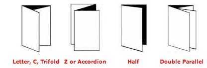
Primary Paper Folds
- Z-Fold Machine
- 3D printed Paper folding machine
2nd Version
Origami Folding by a Robotic Hand, this study, conducted by Kenta Tanaka, Yusuke Kamotani, and Yasuyoshi Yokokohji, explores the application of a robotic hand in the art of origami folding. Through their experiments, they demonstrate that a system comprised of four three-degree-of-freedom robotic arms can perform precise manipulation of paper, enabling it to accomplish intricate origami tasks. The findings of this research highlight the advanced capabilities of robotic hands in engaging in origami activities. Link
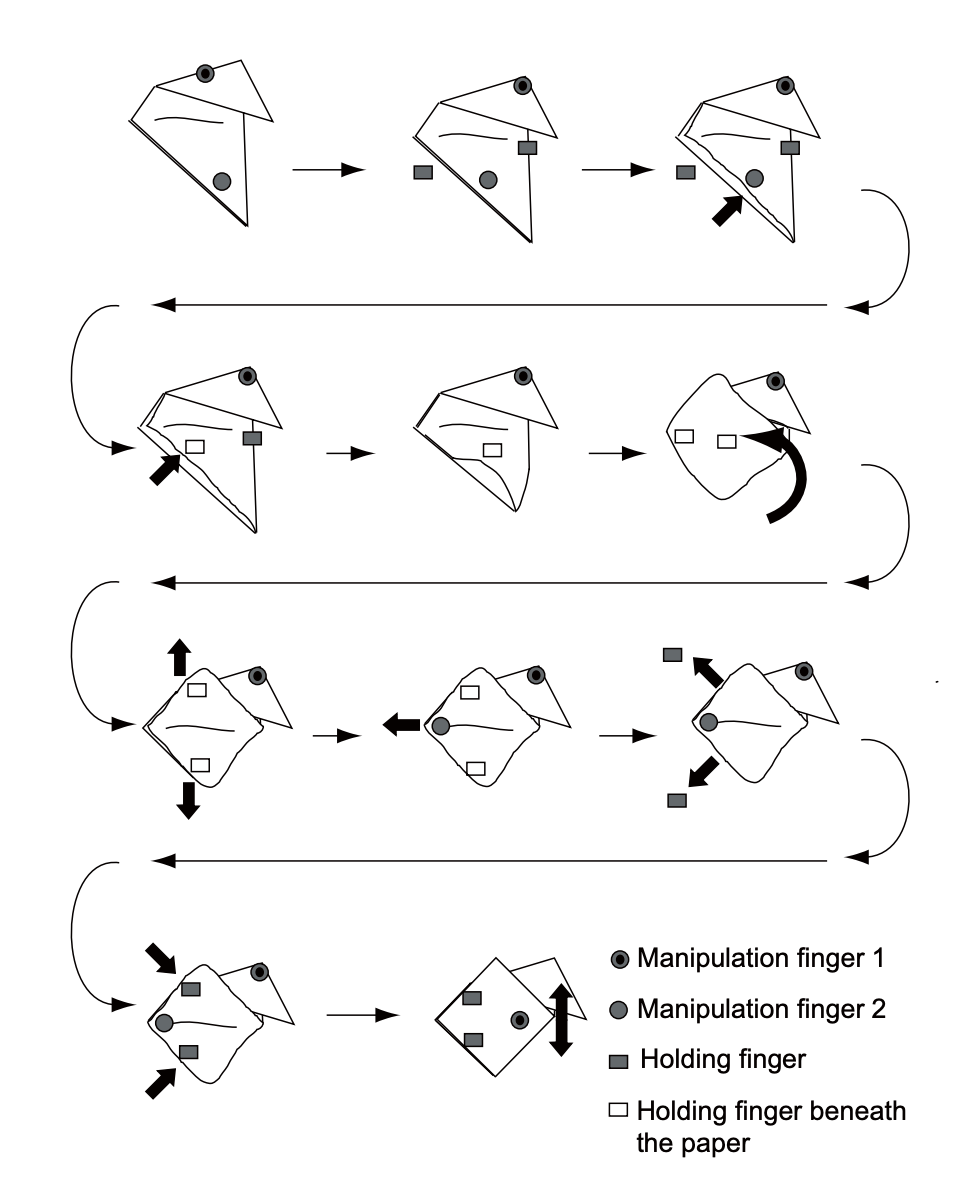
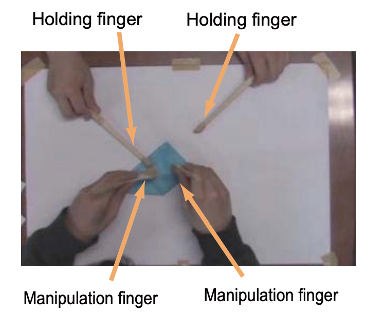

design purpose and goals
- Design a robot that can fold a sheet of origami paper in half on a table as shown in Fig.1. The accuracy of folding must be the same as for a human and the robot configuration should be as simple as possible.
- The approach to design a specialized machine should not be taken. In other words, keep the table flat and do not use any jigs.
- Do not be constrained by the appearance of the human hand when designing a robot hand.