Week14 - wildcard week
Assignment
assignment:
- Design and produce something with a digital fabrication process (incorporating computer-aided design and manufacturing) not covered in another assignment, documenting the requirements that wer assignment meets, and including everything necessary to reproduce it.
Overview
I enrolled in a course focused on reverse engineering, where I learned to use CT scans and various tools to disassemble both familiar and unfamiliar components, aiming to deepen my understanding of their functionality.
This course includes multiple disassembly exercises of parts and components used throughout the program. These exercises are designed to enhance our comprehension of the mechanisms, strengths, and weaknesses of these components. Mastering the technique of teardowns (dismantling and reassembling objects to understand their workings) is a valuable skill. It serves as an effective initial step in exploring and learning about new technologies.
Results
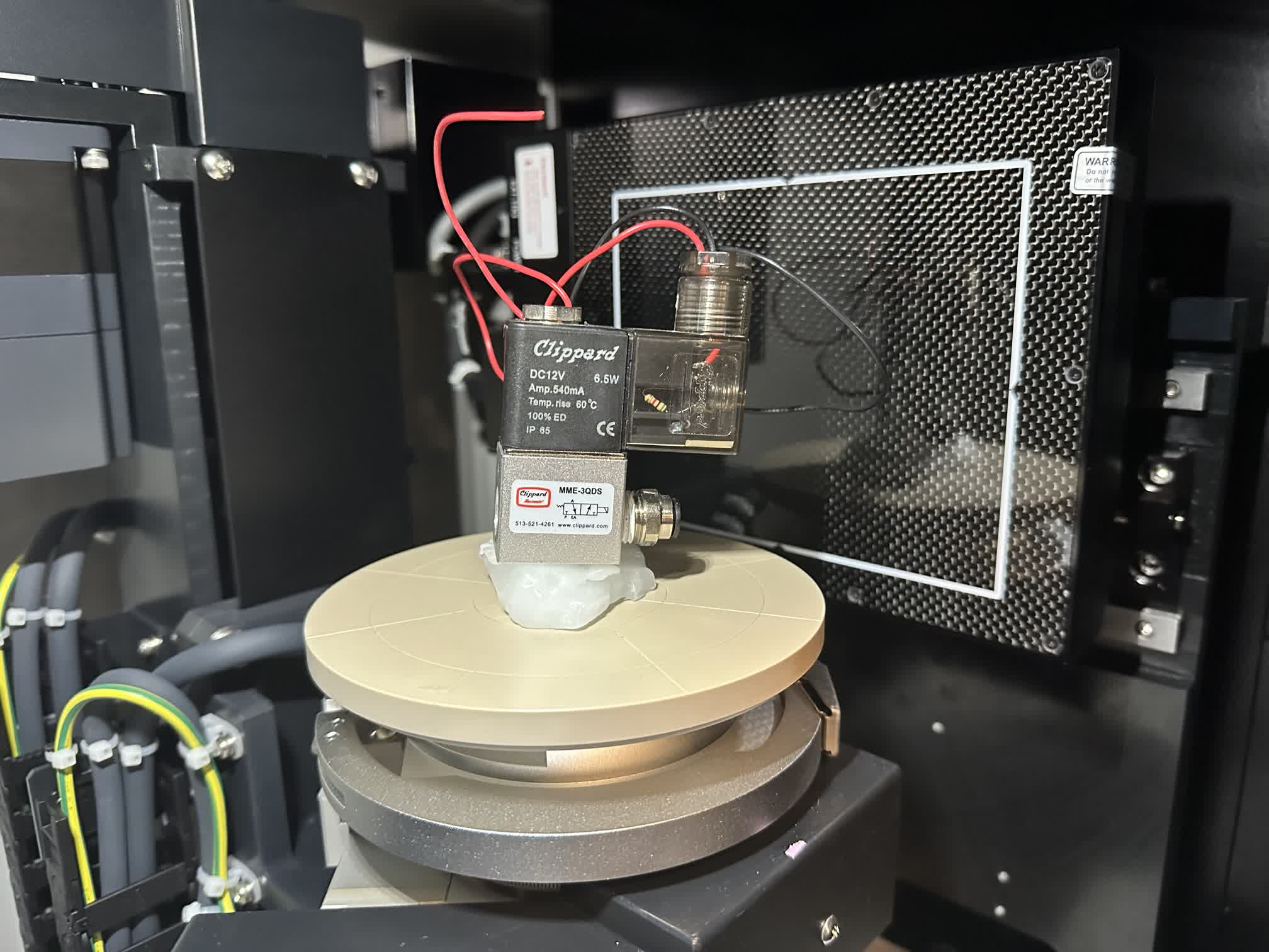
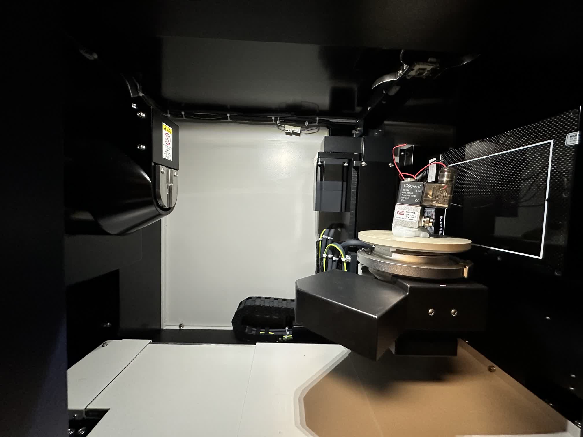
About the Machine
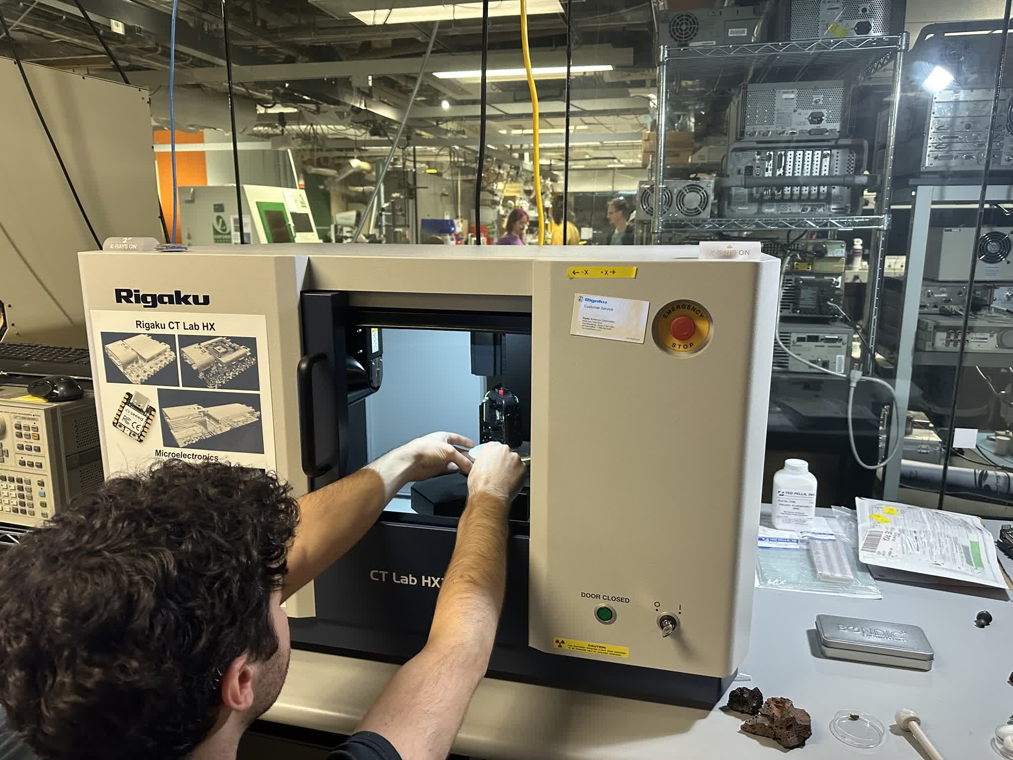
Rigaku CT Lab HX is a benchtop micro CT (computed tomography) scanner. The adjustable SOD (source-to-object distance) and SDD (source-to-detector distance) make this benchtop micro CT scanner flexible. It covers from 2.1 um voxel resolution in the high-resolution mode and 200 mm FOV (field of view) in the large FOV mode. The CT Lab HX is equipped with a 130 kV - 39 W high power X-ray source. The X-ray source settings and X-ray filters are adjustable to optimize the X-ray energy to various sample materials and sizes.
Rigaku CT Lab HX uses the cone-beam geometry. This geometry uses the X-ray beam divergence to magnify the sample image. The magnification factor is determined by the ratio of SOD (source-to-object distance) and SDD (source-to-detector distance). So to achieve high resolution, we can increase the SDD and/or decrease SOD. CT Lab HX has the flexibility to do them both in its compact design.
With the long SDD and short SOD settings, we can achieve 2.1 um voxel resolution (~ 5 um spatial resolution) on the CT Lab HX. This resolution can reveal micro cracks, voids, fibers in composites, etc.
Operating Steps
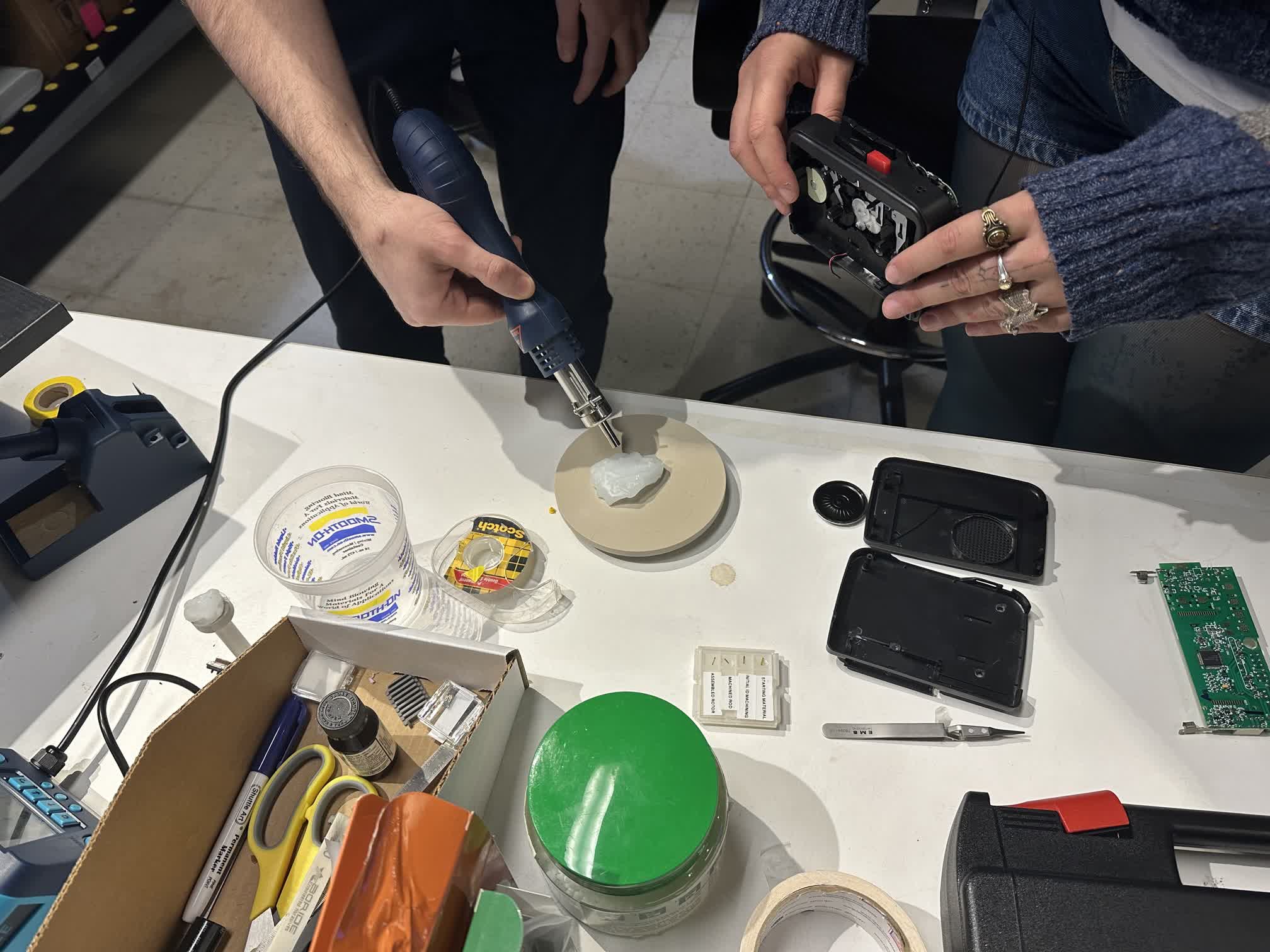
- Sample Selection and Preparation: Begin by selecting the electronic component sample for CT scanning. Ensure that the sample’s surface is clean, free of impurities, and without loose components. To facilitate secure fixation without compromising image quality, the sample is often embedded in heated wax. This wax serves the dual purpose of stabilizing the component during scanning while not adversely affecting the imaging process.
- Sample Positioning: Accurately position the electronic component on the scanning stage of the CT scanner. Ensure that the sample is centered within the scanning area and securely fixed in place to prevent movement during scanning.

The FOV (field of view) we can cover in one scan is limited by the size of the detector. However, the offset scan mode doubles the effective detector width to cover a wide FOV without having to change the detector. Rigaku CT Lab HX utilizes this scan mode to achieve 200 mm FOV without having to change the detector or compromising its compact system size.

- Setting CT Scan Parameters: Determine the appropriate CT scan parameters, including X-ray energy level (voltage) and current (amperage). The choice of voltage and current depends on whether we want to emphasize plastic or metal components within the sample:
- Higher voltage and current settings are often used to emphasize metal components and achieve better penetration, which is useful for inspecting solder joints and metal parts. Lower voltage and current settings may be preferred when focusing on plastic components, as they provide better contrast for non-metallic materials.
- Performing CT Scanning: Once the parameters are set, initiate the CT scan using the scanner. The device will rotate around the electronic component, emitting X-rays to capture projection images from various angles. These images are essential for the subsequent reconstruction process.
-
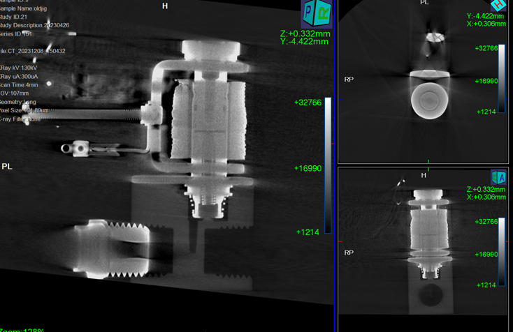
Data Reconstruction Principle: After the scanning is complete, data reconstruction is performed using specialized CT image processing software. The principle involves a mathematical process called backprojection, where the projection images acquired from different angles are used to reconstruct a 3D volume. This volume represents the internal structure of the electronic component. Think of it as creating a cylindrical volume from 2D projections acquired at various angles.
-
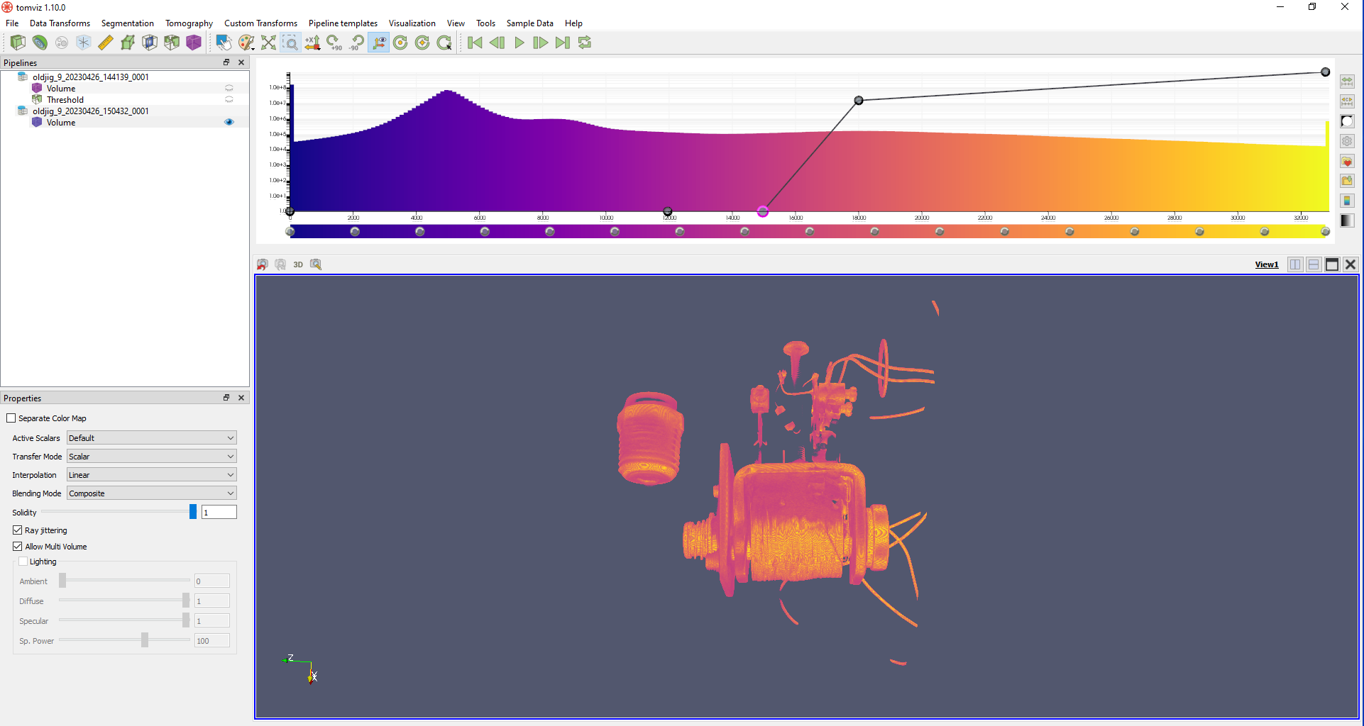
Image Analysis: Analyze the reconstructed 3D volume or specific 2D cross-sections to gain insights into the electronic component’s internal structure, defects, or solder quality. Various image processing tools and techniques can be applied for this analysis.
- Result Export: Depending on the analysis requirements, export the 3D volume data or specific 2D images for documentation, reporting, or further engineering analysis.
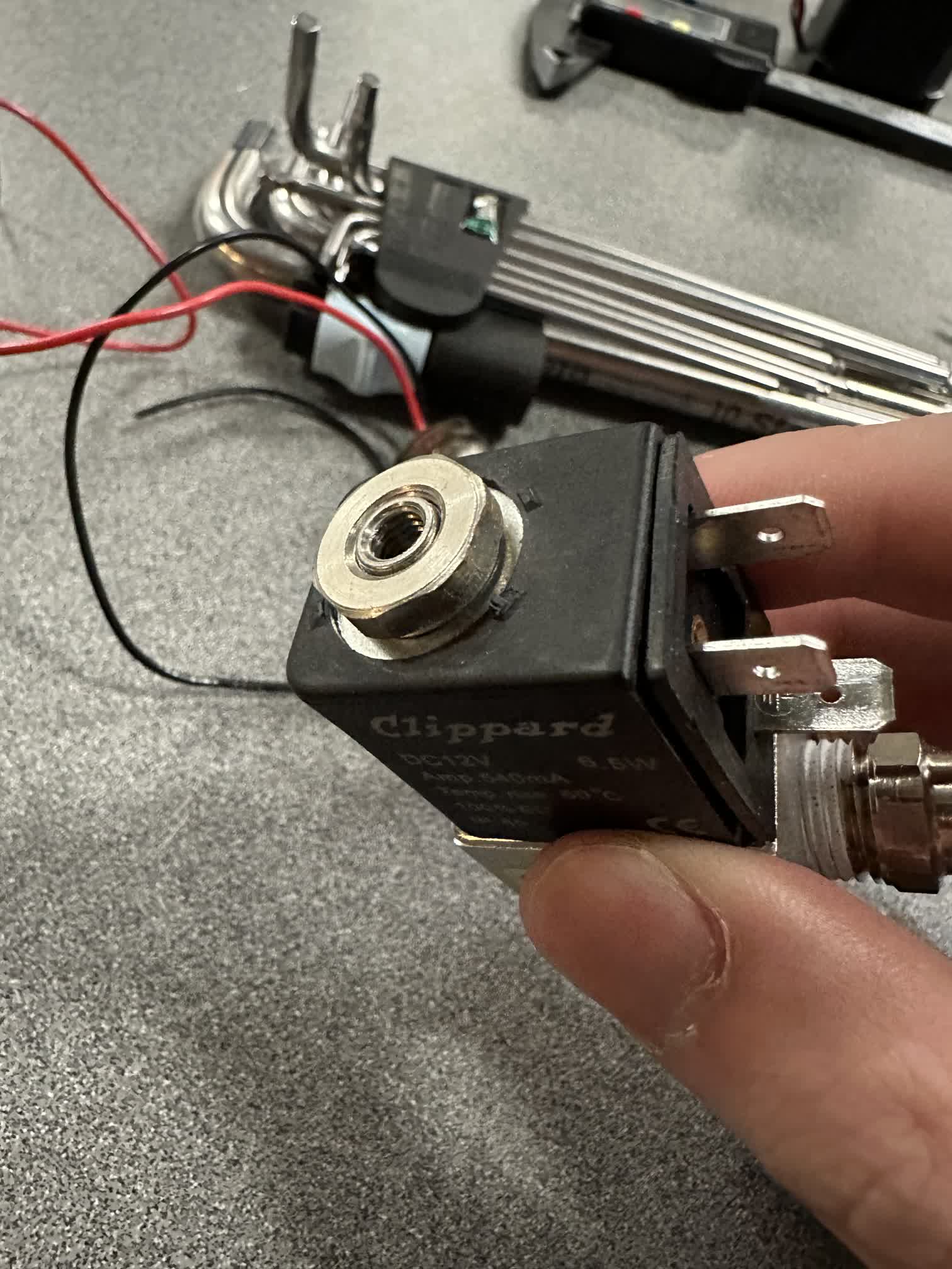
Reverse Engineer a Solenoid Valve
Initial State
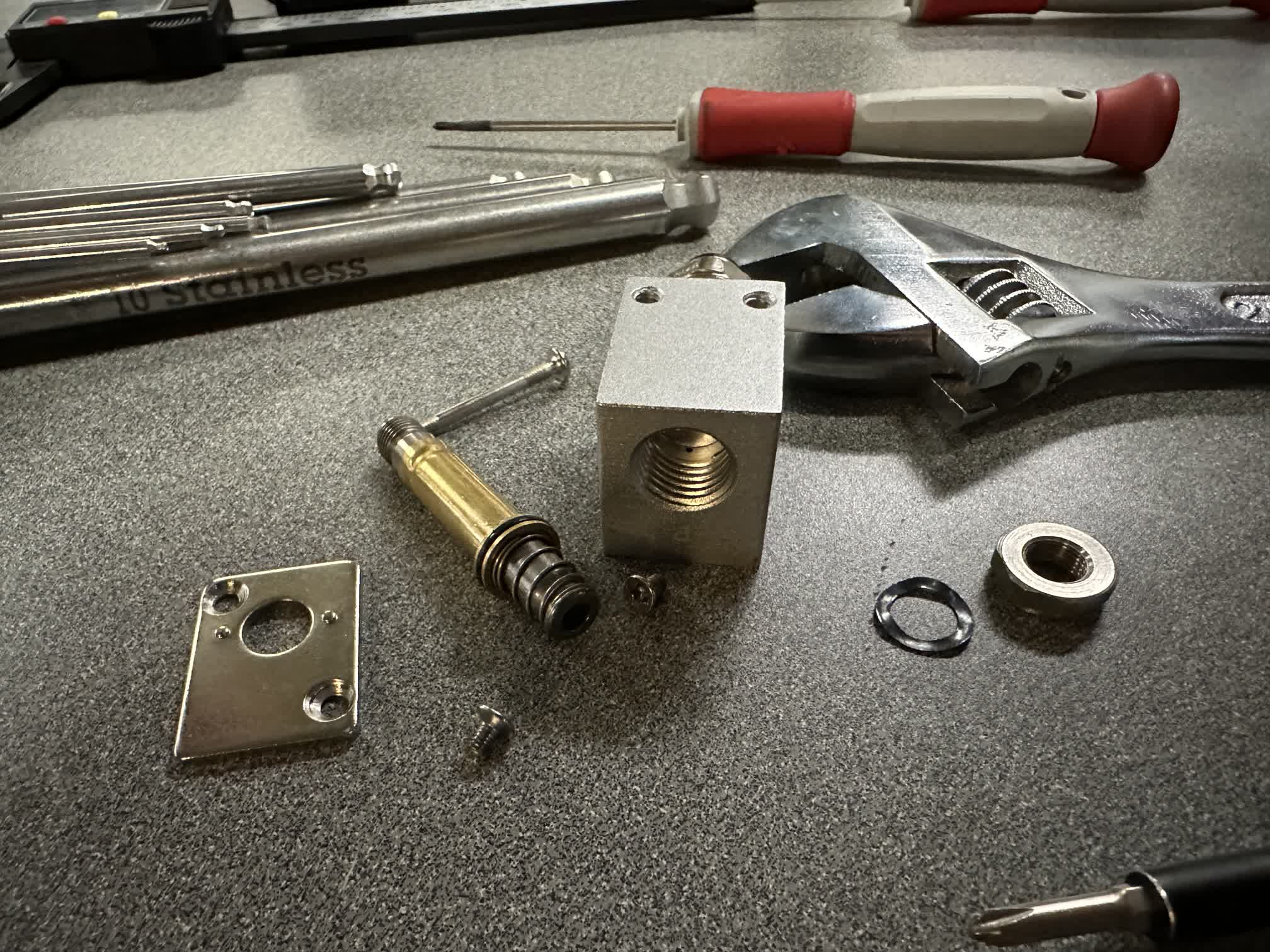
This is my first encounter with this electronic component. The objective is to combine the results of a CT scan, manually dismantle all components, and test them to understand the fundamental principles of how the components work.

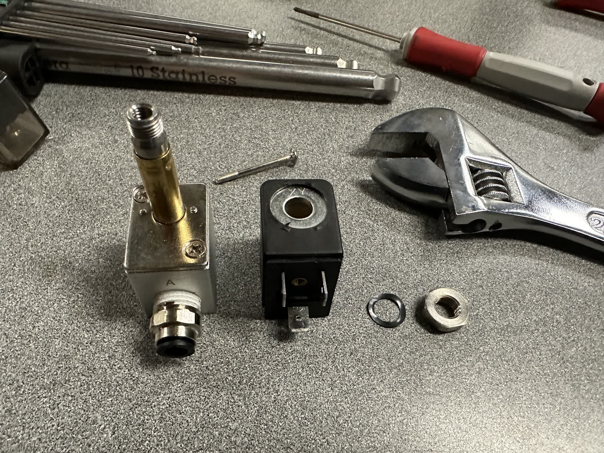
Step-by-step disassembly of components
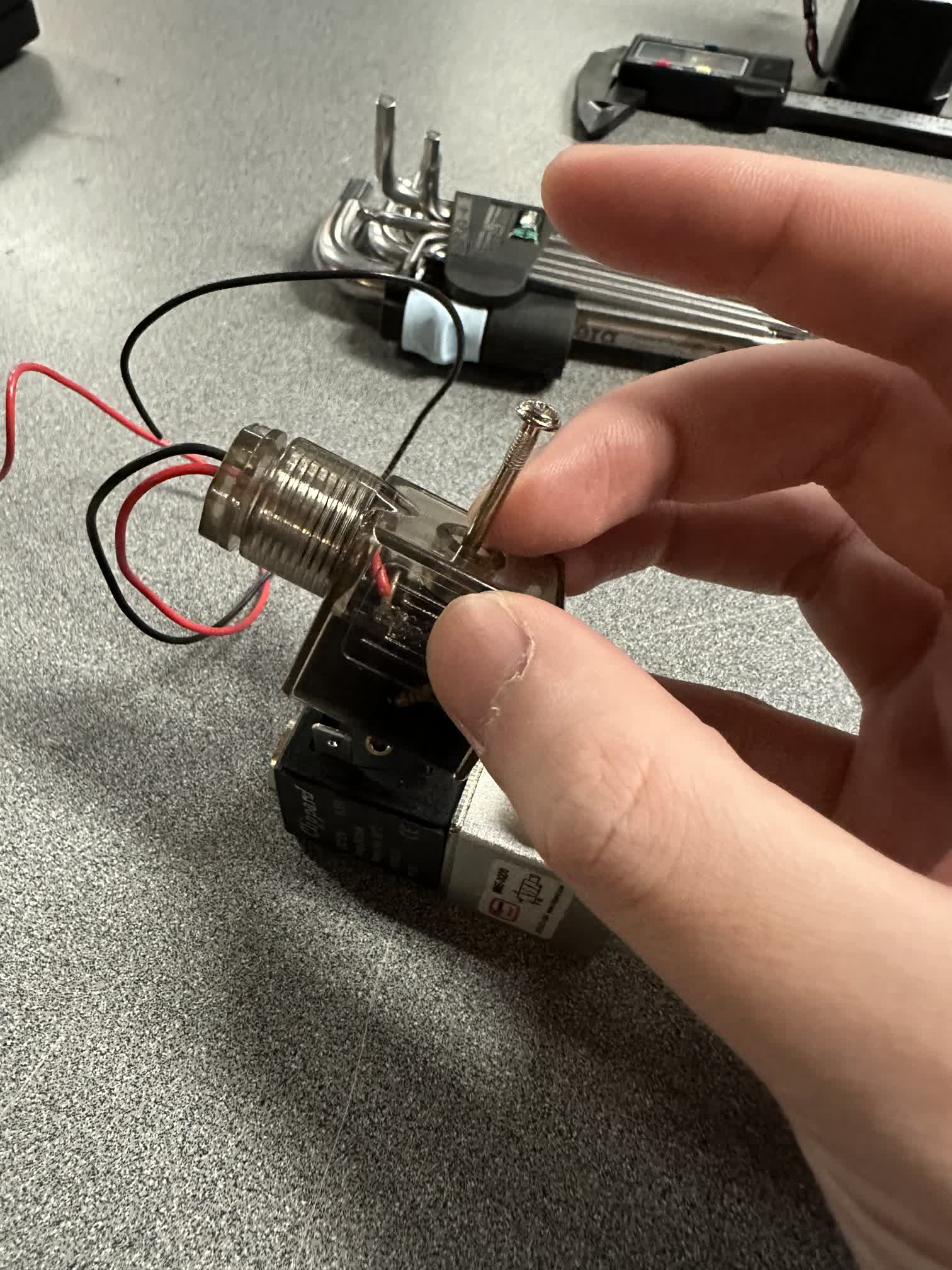
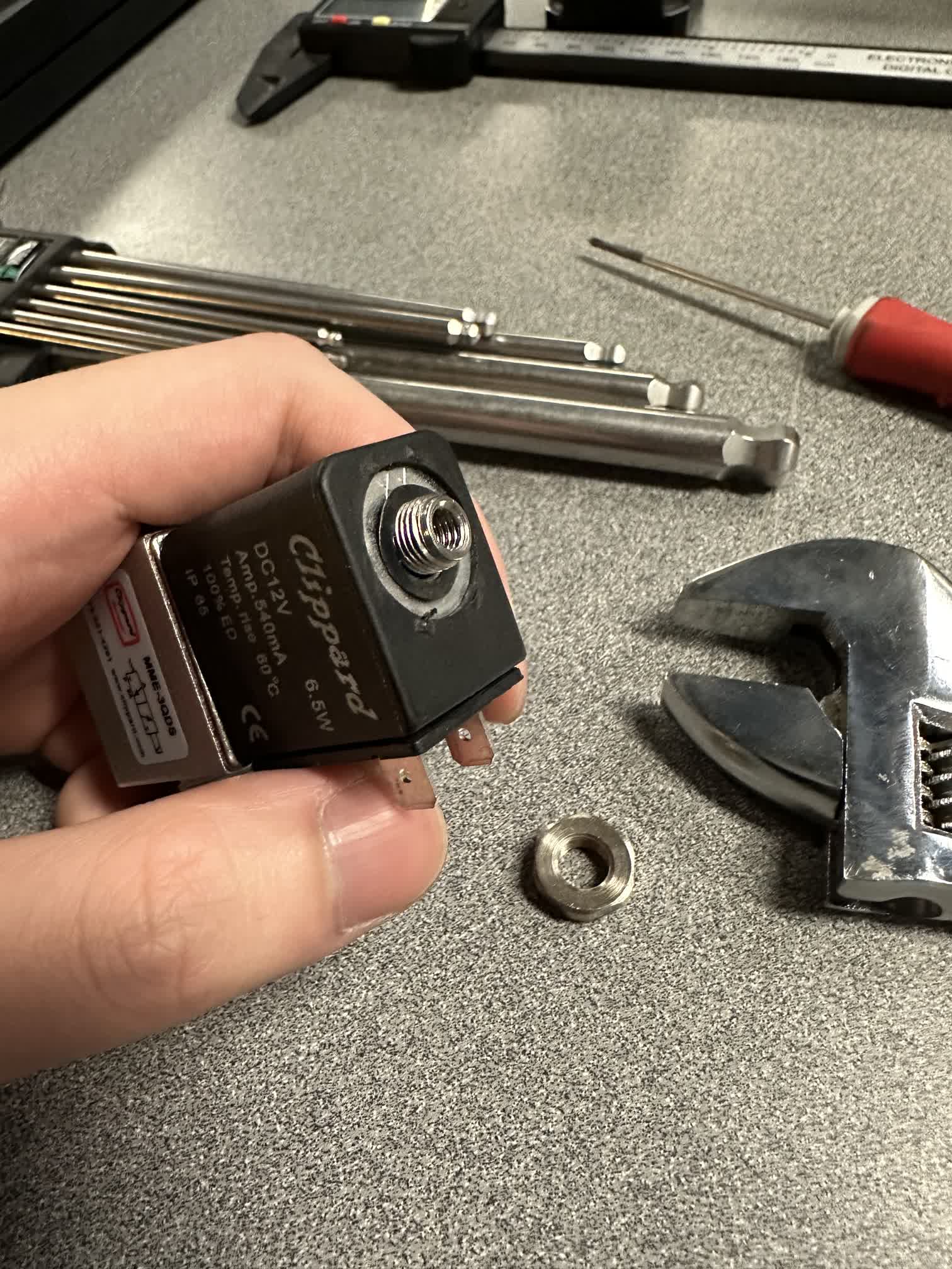
Study of the Structure and Working Principle of Solenoids
I am applying electricity to this component to further study the function and principles of the solenoid part(electromagnetic coil).
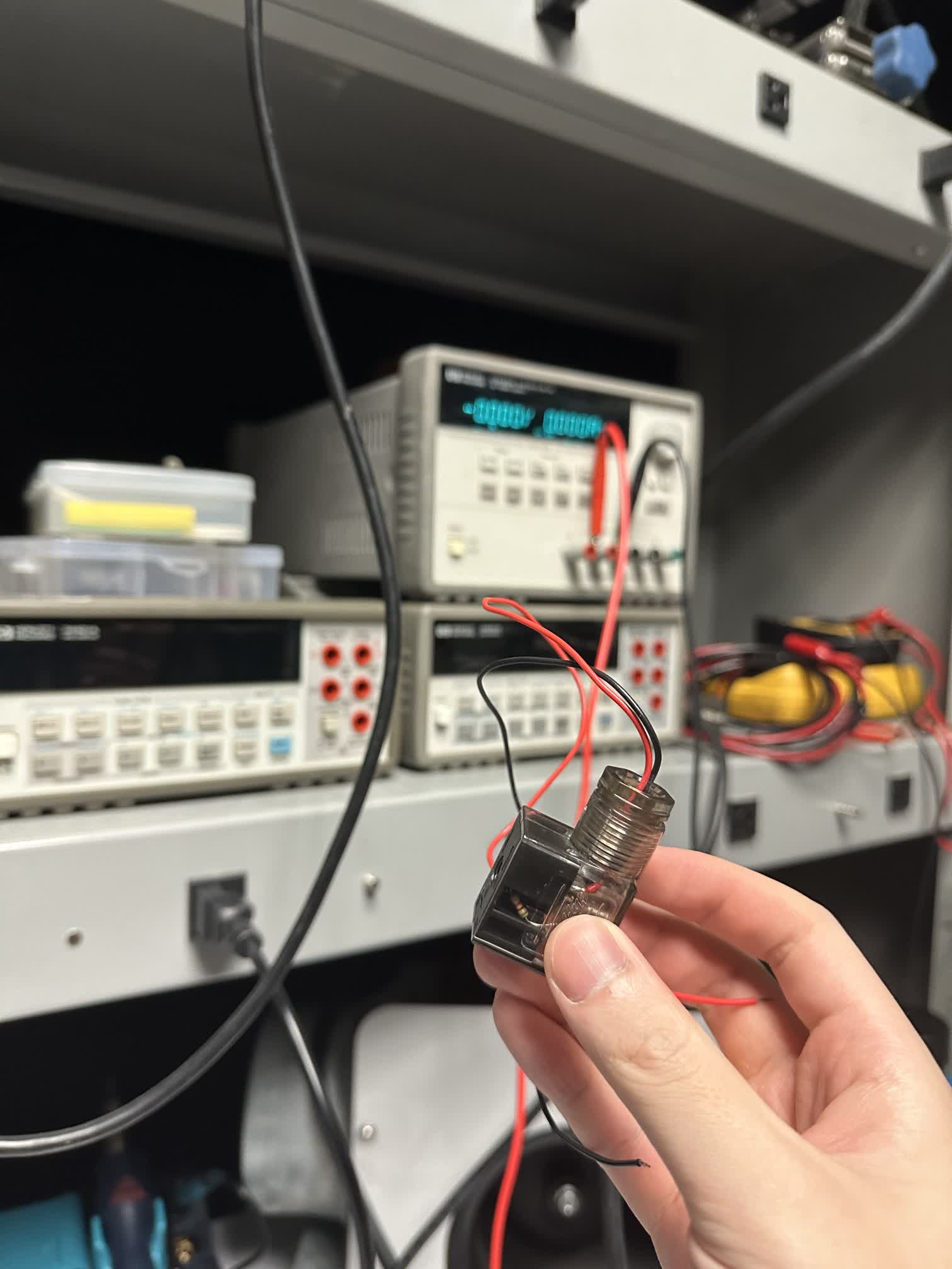
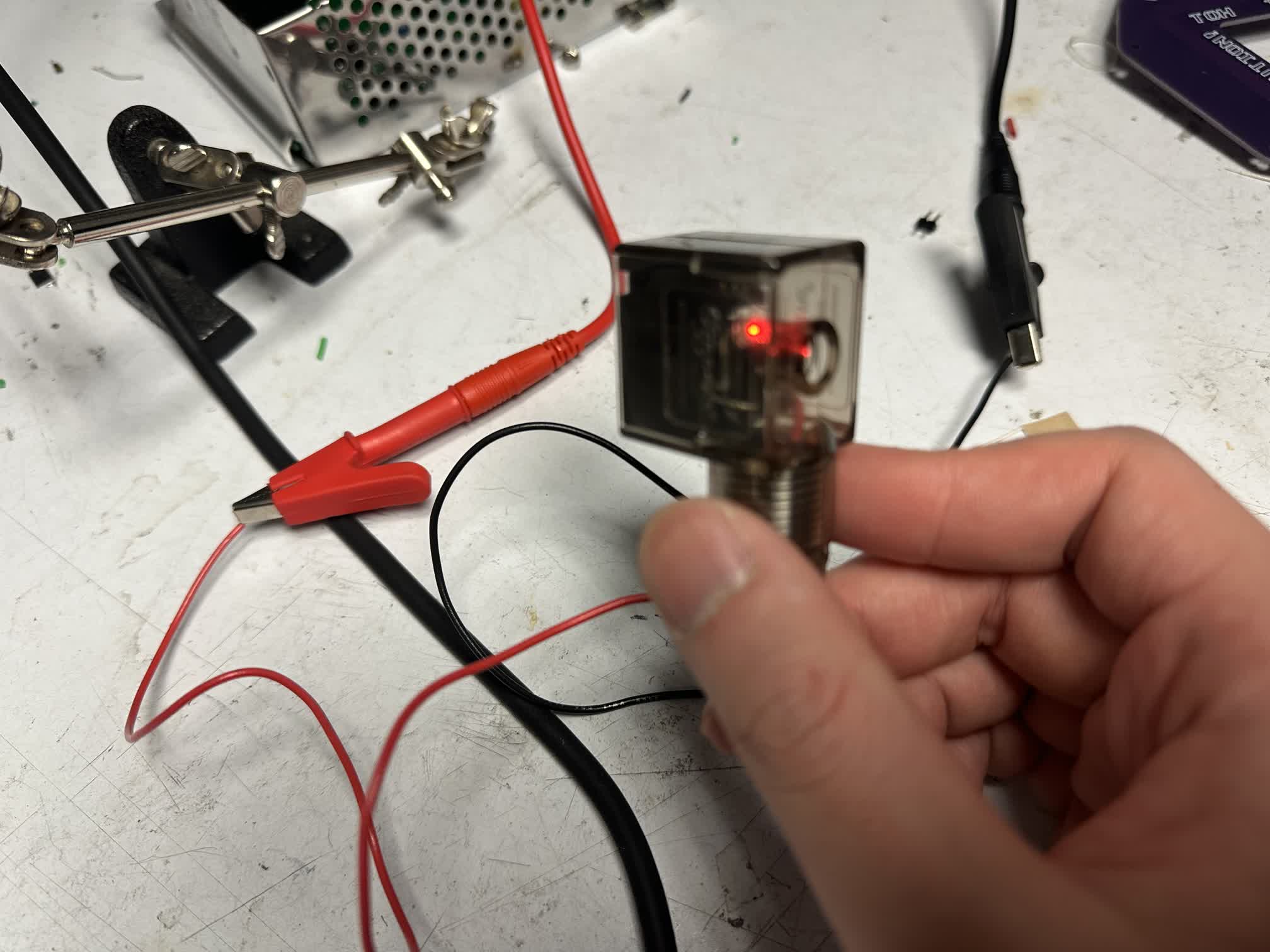
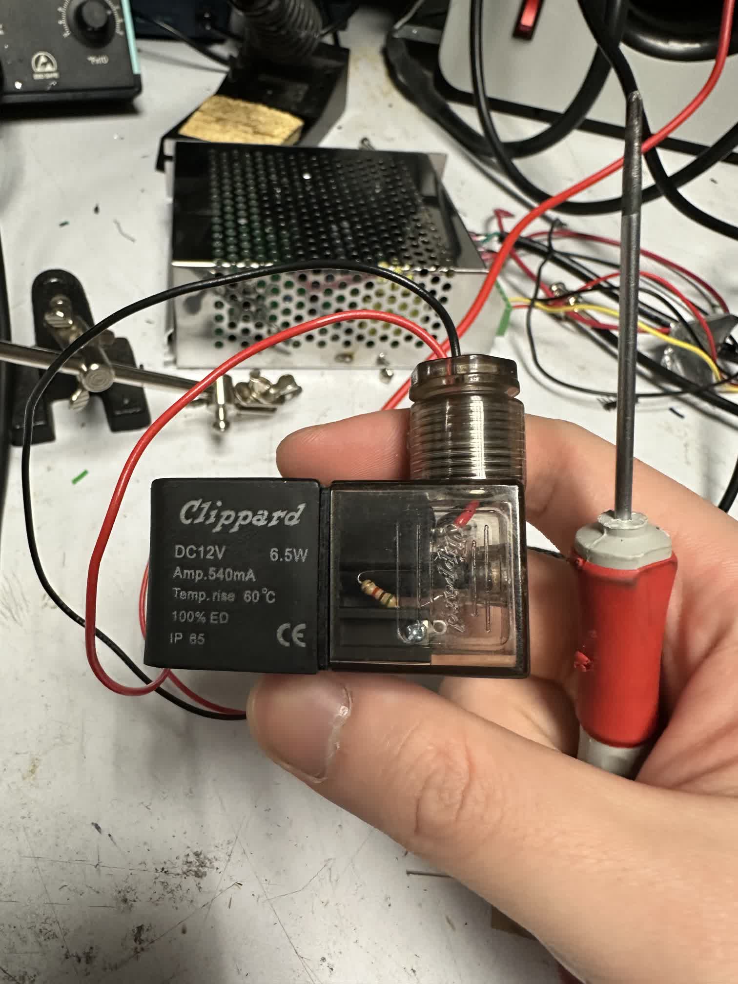
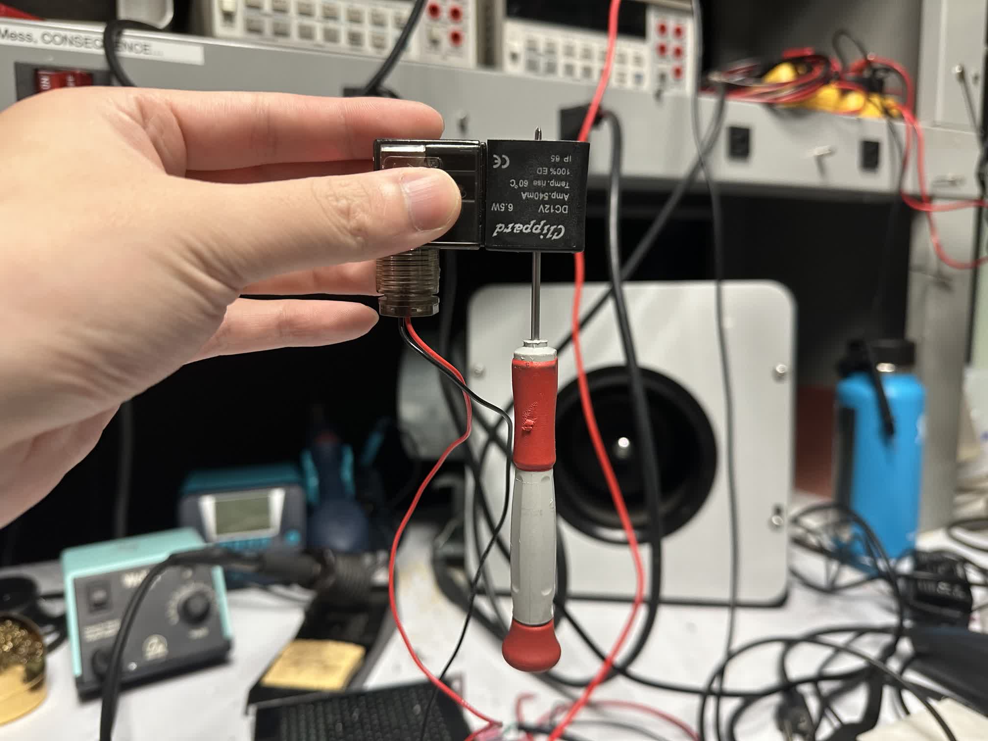
Solenoids are cylindrical coils of wire that act as electromagnets when electric current passes through them, commonly used to convert electrical energy into linear motion or mechanical action.
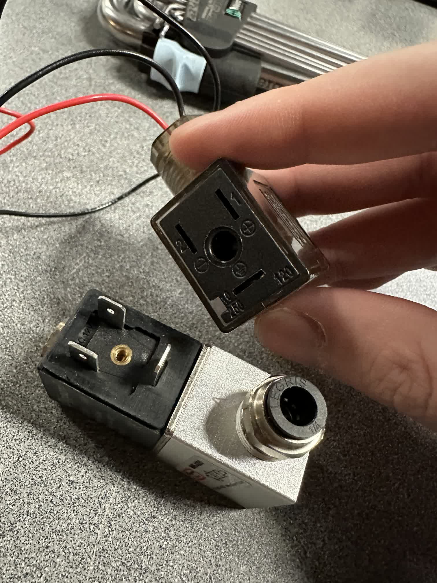
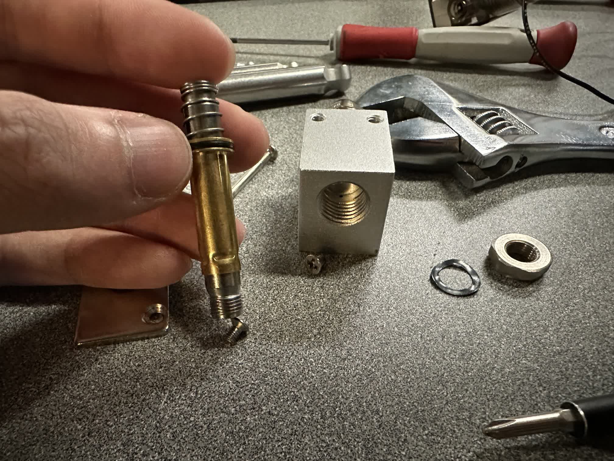
Study of the Structure and Working Principle of Valve
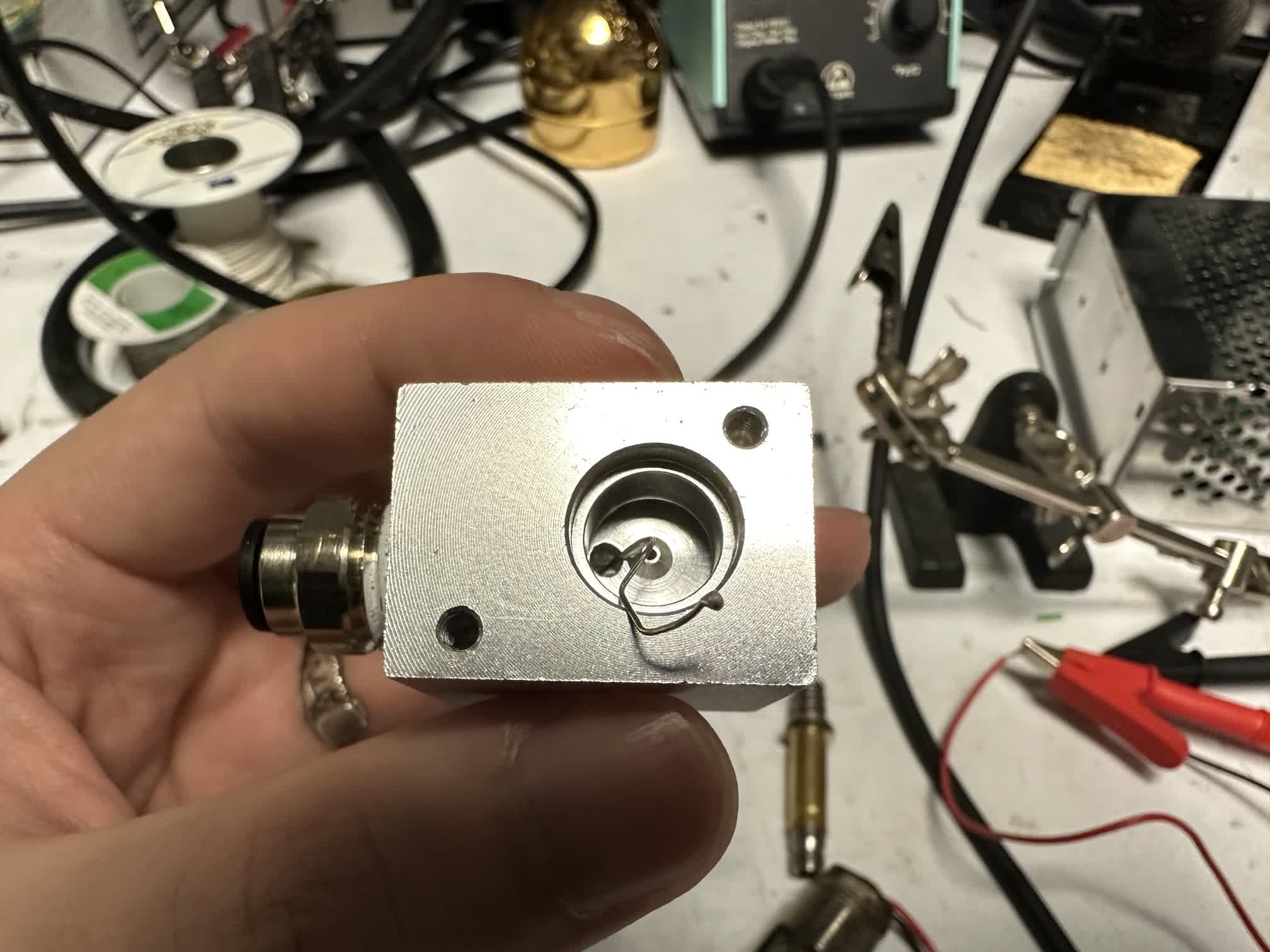
I used a piece of tin wire to probe the different outlets and inlets of a valve to explore its connectivity, and further confirmed the functionality of this electronic component by using a method of blowing air.
Conclusion
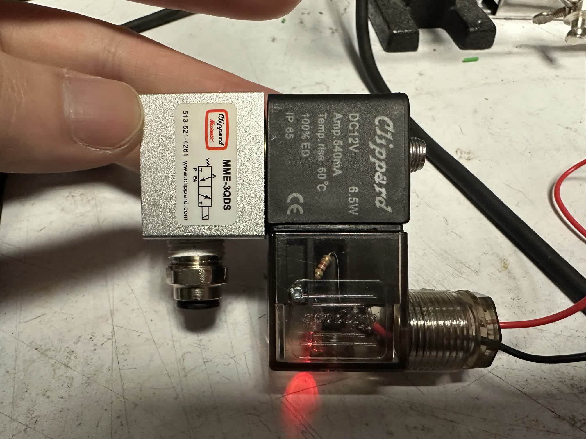
A solenoid valve is a device used to control the flow of liquids or gases using electromagnetic force to operate the valve. It typically consists of an electromagnetic coil and a valve body. When an electric current passes through the electromagnetic coil, it generates a magnetic field that either attracts or pushes the valve core, thereby changing the valve’s state to allow or block the flow of liquid or gas.
I successfully reassembled it, and it is now functioning properly
Special thanks to Dave for such detailed and clear step-by-step instruction; I have learned a lot.