SAMD21 is a microcontroller that is good at capacitance (Quentin used this for touch board)
Week 05
Electronics design!
Tools: Autodesk Fusion 360 and/or KiCad
Previous experience: none
This week, we set out to learn how to design a printed circuit board (PCB) - both the schematic and the physical board layout. I decided to continue to use the program Autodesk Fusion 360. This is the same program I have been learning for CAD projects, so I wanted to continue working in the same "world". My objectives for this week were relatively simple:
- Design and create a schematic of a simple PCB
- Get the LED on the RP2040 microntroller to blink when clicking a small button/switch
So, what exactly did I do this week?
I went to office hours with Quentin on Friday, October 6th
I learned that it is common to have a “pull up” resistor built into the microcontroller. I need to have “pull up” to tell resistor what to do, otherwise button will be “dangling”
I learned that GPIO will be limited to 2 milli-Amps and a resistor should be around 1,000 Ohms on our board
I setup Autodesk Fusion 360 with my MIT email account, clicked on the data panel, and joined the MIT HTMA “team”. From there, I was able to access the “fab” libraries, which includes microcontroller schematics such as the Xiao RP2040. The first thing I did was put the RP2040 schematic on my new schematic file, and also created a “PCB” document. Autodesk Fusion 360 has two main interfaces I worked in: 1) “Schematic Document” where I could create the schematic and the location of the components does not matter or reflect reality, and 2) “PCB Document” where the components of the board need to be arranged and placed in a way that represents reality and what I will make.
I added a button to the schematic, called “SW_SWITCH_TACTILE_6MM”
I added an LED with the intention to control the existing LED light on the Xiao RP2040 board, it is called “LED”, variant “FAB1206”
I added a resistor to control the current that travels to the LED. I added the resister named “R” to the schematic. I gave the resister a value of 1000 ohms by clicking the icon “R2 10K” under the Modify section of the toolbar
I added the label for ground “GND” to the schematic after the LED, the button, and the GND pin/terminal on the RP2040. I did this because I learned that things that have the same name are connected together automatically. I also learned that I should arrange things in a way that make sense to read, not necessarily in the best way to arrange the board - that comes in the next stage when we move to “PCB document”.
I then switched to “PCB document” where I moved the components of the schematic to my new board. This was tedious and required many clicks and drags to get the components in a lay out that looked organized. I used the tool “Route Manual” to create the routes between components.
I updated the clearance values to 16 mil in the DRC settings. I got there by typing “drc” in the command line on the PCB document tab. At first, I had multiple odds and ends of lines that I needed to delete to clean up the board. Eventually I could run DRC without getting any errors. See the video below of how I ran this.
Finally, I used the “Modify” tool to make the physical size of the board smaller. My first simple board design is done!
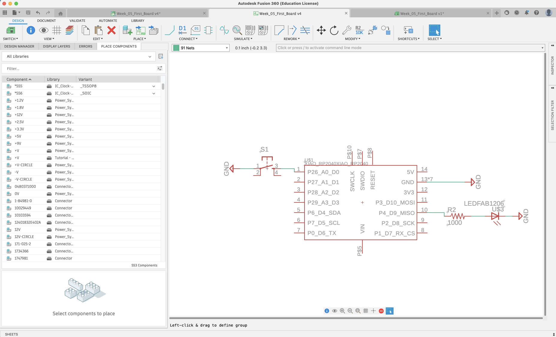
A screenshot of a simple schematic I made in Fusion 360
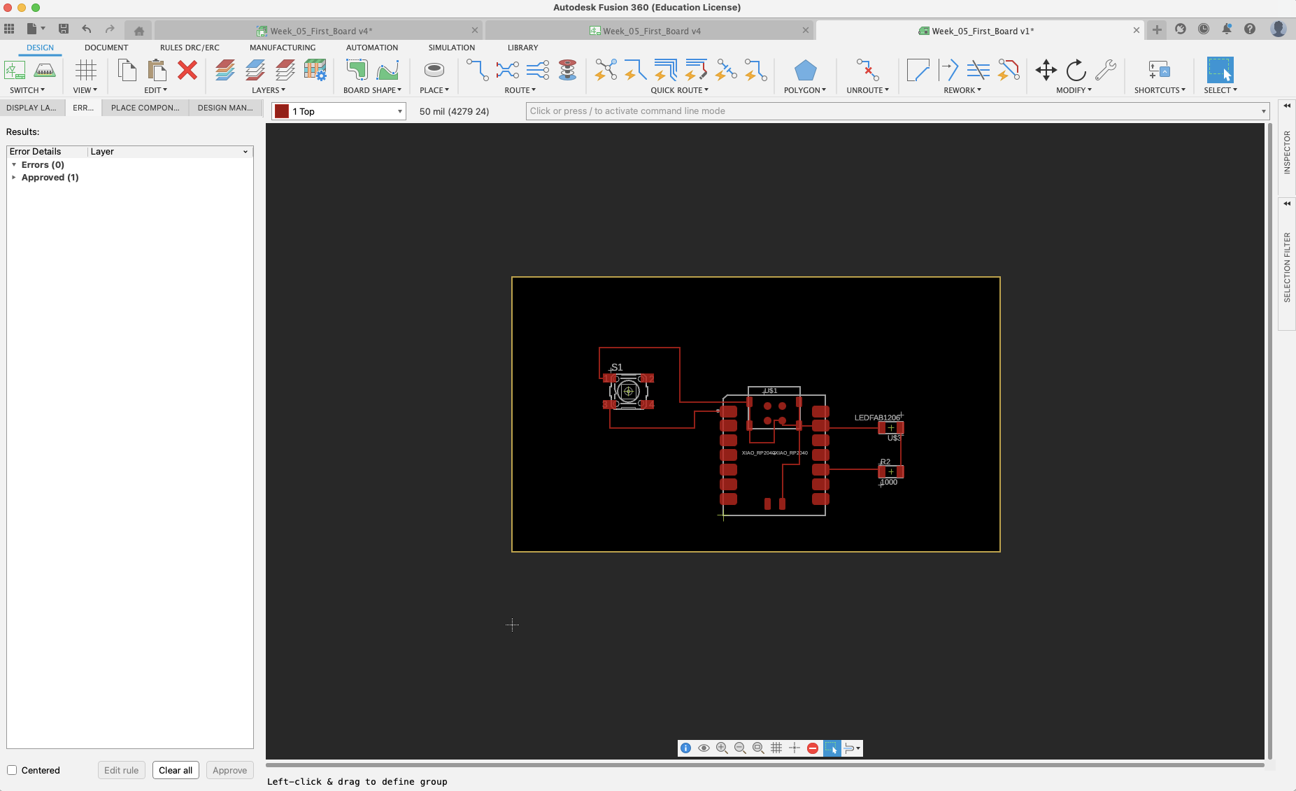
A screenshot of a simple PCB I made in Fusion 360 from the schematic above
After I finished designing the schematic and PCB, I ran a "design run check" by calling "drc" in Fusion 360's command line
I ordered an "Electronic Fun Kit" on Monday, and it arrived on Tuesday, so I kept going
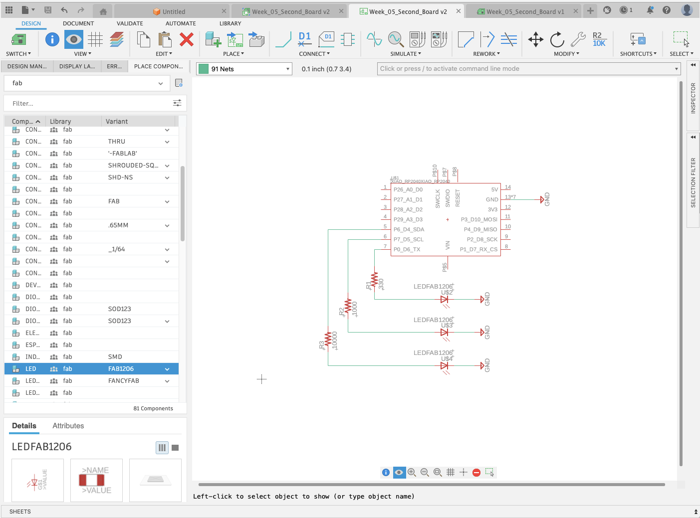
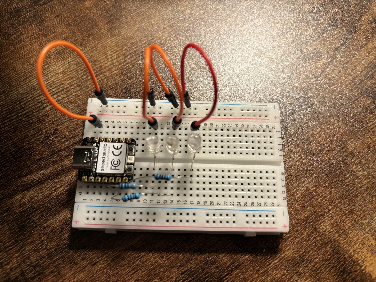
With the electronic fun kit, I made my first bread board. I decided I would first design a schematic and PCB with three external LEDs and three different sized resistors to see
the impact on the brightness of the LEDs. I created a simple schematic and board - see images below. I then created that same schematic in real life on a bread board, and wrote a simple
micropython sript to turn all the lights on, then off, then on in sequence. Finally, the program prints "i'm dimming" after each sequence.
Here is the micropython code file.
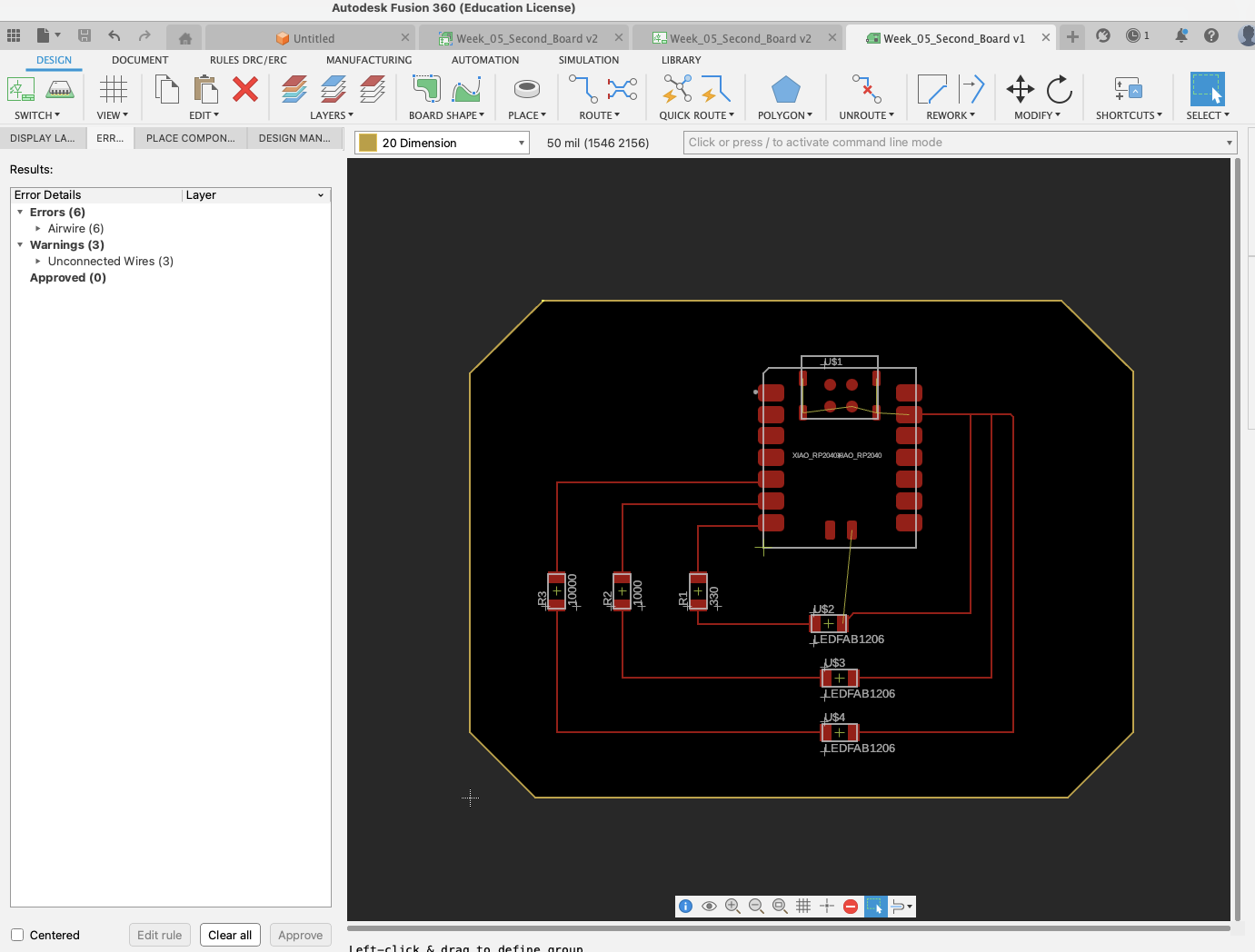
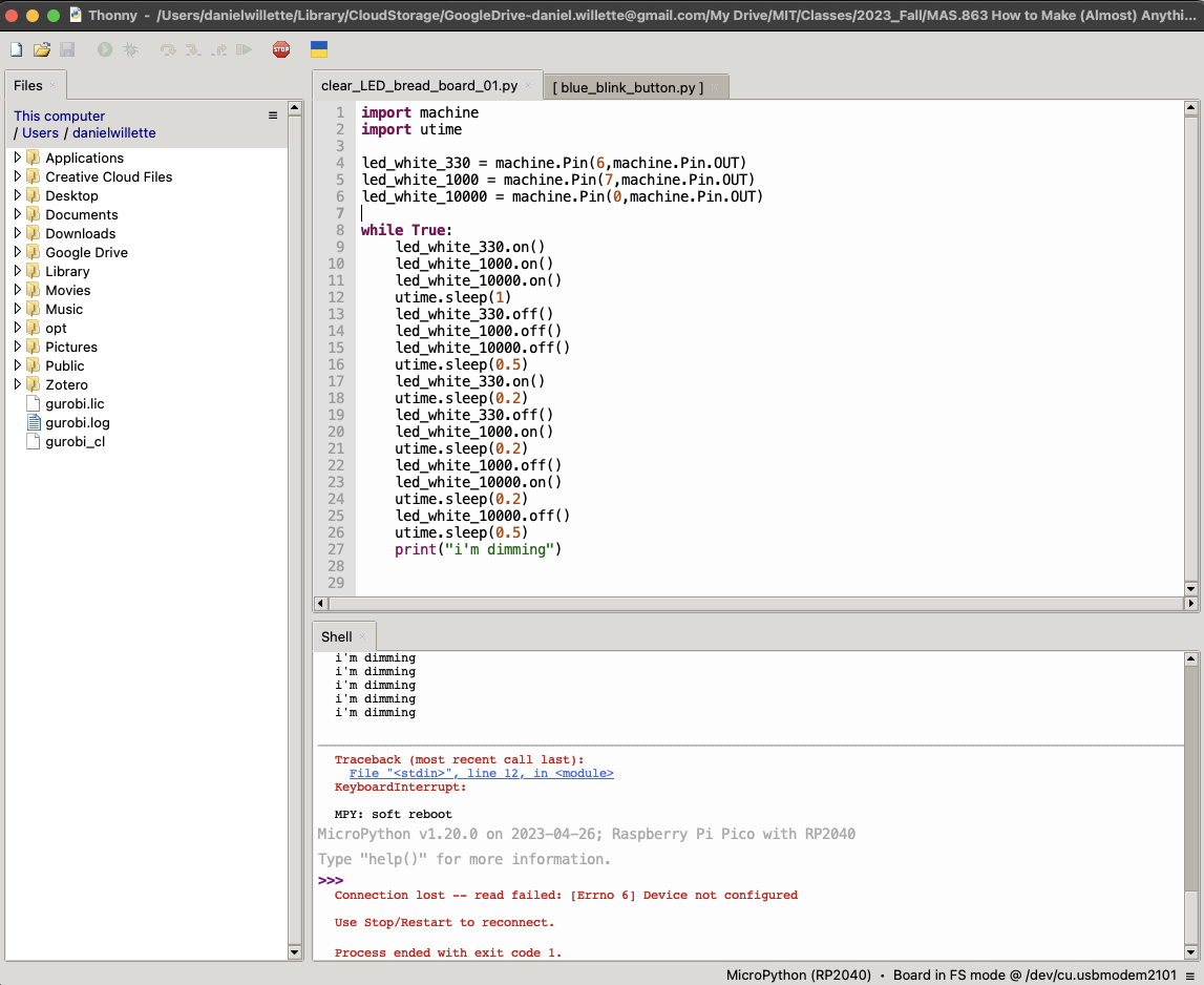
A simple program to turn on the LED lights with different reistors. Through this, we can see the varying brightness with resistors ranging from 330 ohms to 10,000 ohms.