Safety! Take your time, follow all safety instructions, such as wearing safety glasses, wearing gloves, securing loose clothing or hair, and always working in pairs.
Week 08
Computer-controlled machining, aka "make something big"
Software Tools: Autodesk Fusion 360, VCarve Pro, Shopbot 3
Hardware Tools: Shopbot PRSalpha Gantry
Previous experience: limited CAD from previous weeks
Designing a small table
Using Autodesk Fusion 360
Throughout the class, I have continued to use the CAD tool "Autodesk Fusion 360". This week was a chance to develop my skills a bit further. This week, I practiced using functionality including driven dimensions, driving dimensions, constraints, and rectangular patterns. Rather than creating all my bodies in a single plane and assembling the pieces in my mind, I joined the bodies together using the "point to point" move function. While the design is very basic, it took me approximately 3 hours to create. Fusion is still not natural to me, and I spent most of that time thinking through how to setup my dimensions so I can later update a parameter such as the "wood thickness" and have the design update completely with minimal modification.
I successfully designed a table that will fit together securely without screws or glue, assuming minimal differences between my dimensions and cuts.
I realize I am still not using Fusion as effictively or comfortably as I could, but this was admittedly a big step in the right direction.
I also got help from Alfonso who was generous with his time!
I used the "project" function to project new sketches of the bodies onto a new plane, and then exported the sketches of the design as .dxf files.
See the files section on the left navigation bar for the final design.
Short screen recording while traveling through the Fusion timeline
Using the Shopbot milling machine
I used the Shopbot milling machine in the CBA Shop Mars lab with John’s help. I uploaded the .dxf files from Fusion 360 into VCarve Pro on the lab desktop and arranged the pieces on a 96” by 48” piece of material. There were challenges with the units - more on that below. We carefully arranged the files on the board and allowed for about 3 inches of buffer space on the edges of the board. This is because we needed that space for the screws which were securing the board down on the machine bed. We secured the 48” x 96” OSB wood on the Shopbot machine with about 4 screws on each side. We zeroed the machine by eye. We did this by carefully and manually lowered the end mill towards the OSB wood until it appeared as though they were touching; we then zeroed the device. Navigating the Shopbot tool was very similar to the Shopbot Desktop machine we used for molding and casting week. I followed the instructions in the Shopbot User Guide together with John to cut out the OSB wood pieces.
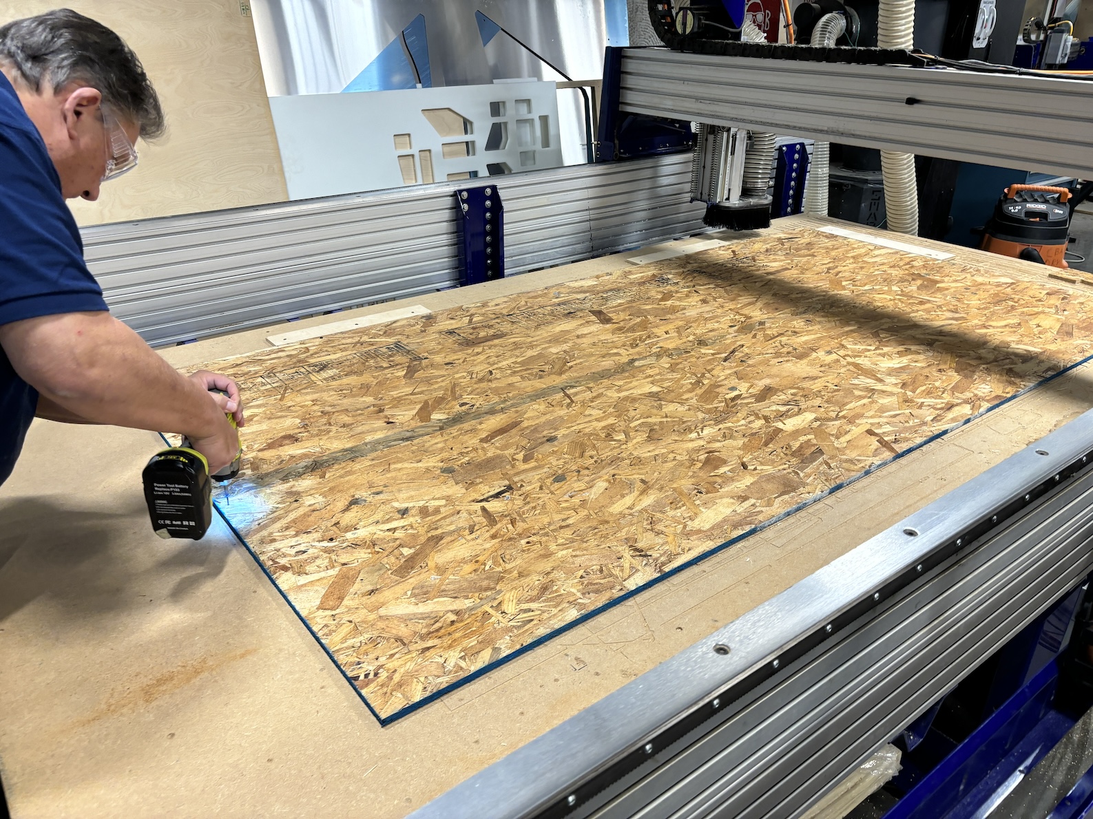
Securing the 4' x 8' OSB wood on the machine bed. Thanks John!
Video of the Shopbot machine running
Challenges/mistakes
- Importing .dxf files to VCarve Pro: the software program ignores units when you import a file. For example, my CAD file was created using millimeters (mm). The VCarve program was set to inches. When I imported the .dxf files, with dimensions in the range of 900 mm, they were imported into the software as 900 inches. John and I could not figure out how to import the file and specify the units so it would automatically convert and use the right dimensions.
- Creating a toolpathThe first time we created the toolpath in VCarve Pro, we did not make the toolpath on the “outside” of the design. Therefore, the first 5 minutes of cutting was done exactly on the vector of the .dxf file, which resulted in milling away too much material.
- End mill diameterI designed my file parametrically assuming the diameter of the mill was 0.125 inches. The diameter of the mill is actually 0.25 inches.
- Wood thicknessThe thickness of the wood was wrong. I had assumed 7/16” in my CAD model, but after the cutting was complete, I discovered that the wooden pieces could not slot together because the peg holes were too narrow.
- Random machine stopThe machine stopped cutting and ignored an entire piece of the table. We learned this was an issue with the vector file - the piece never fully joined.
Images and videos
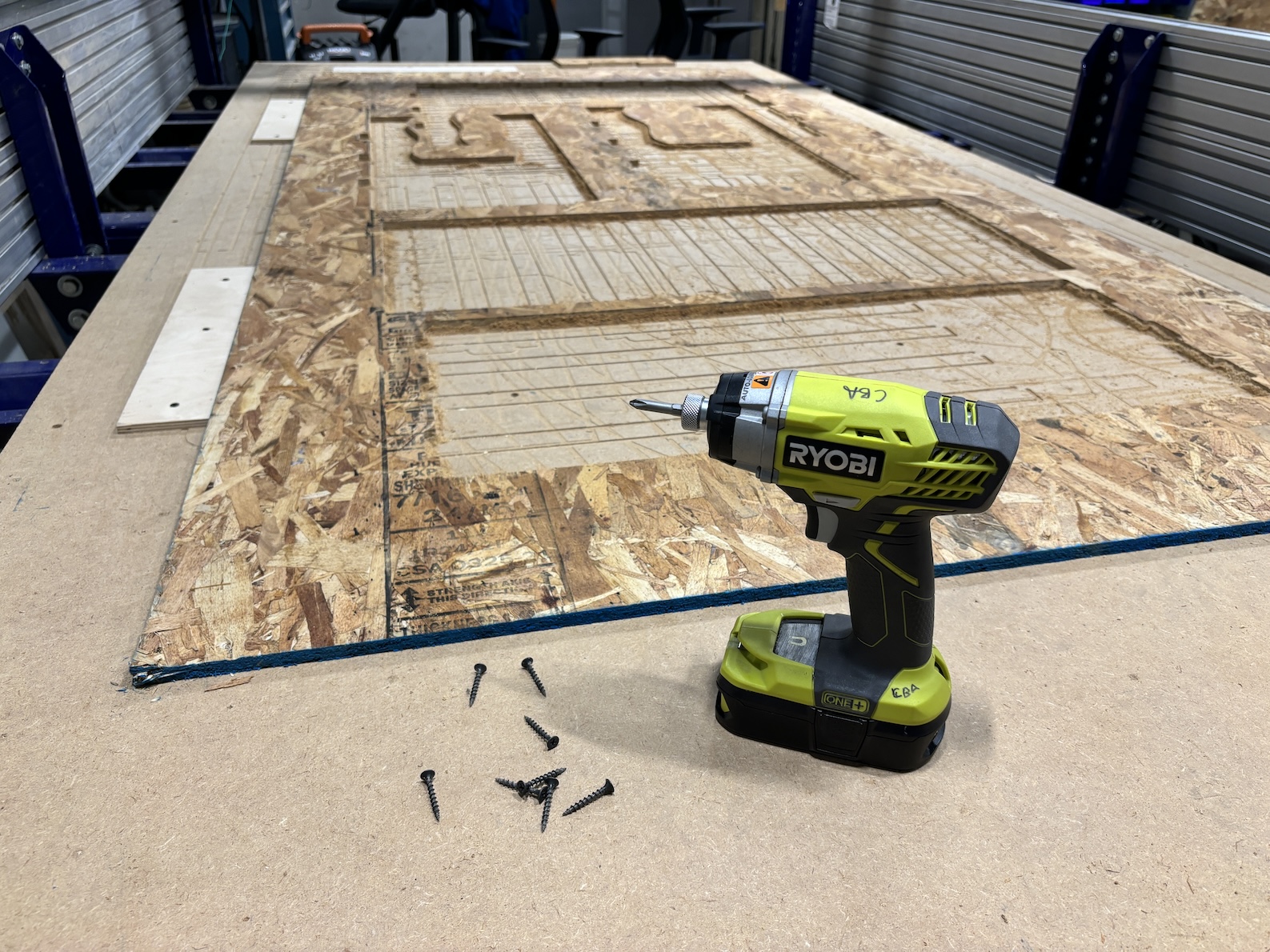
Removing the securing screws after the milling job was done
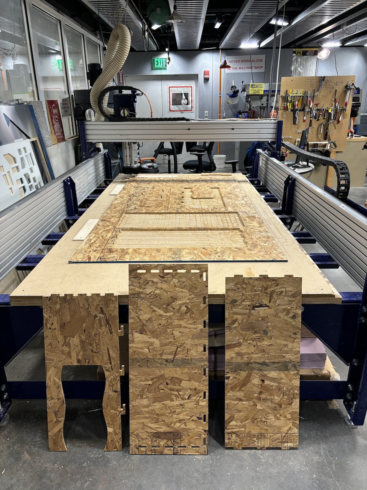
Pieces removed from the bed of the machine
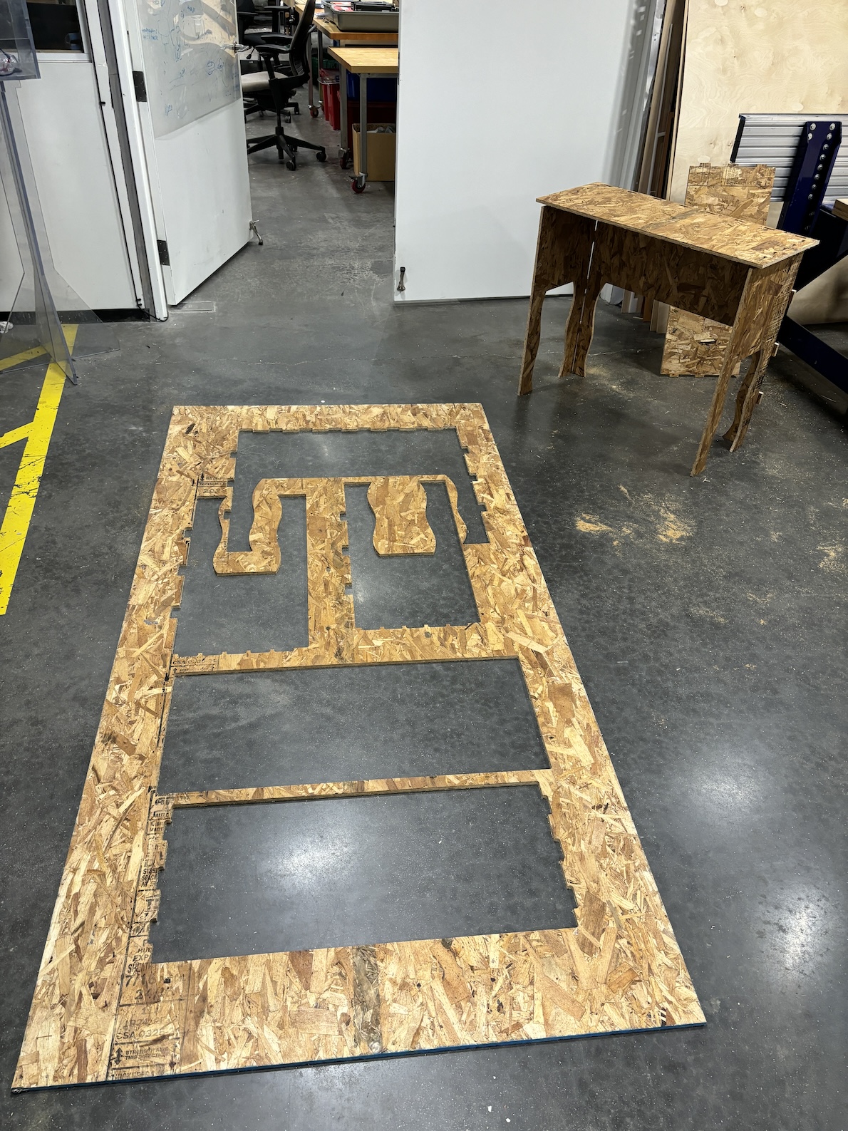
Final scraps after cutting
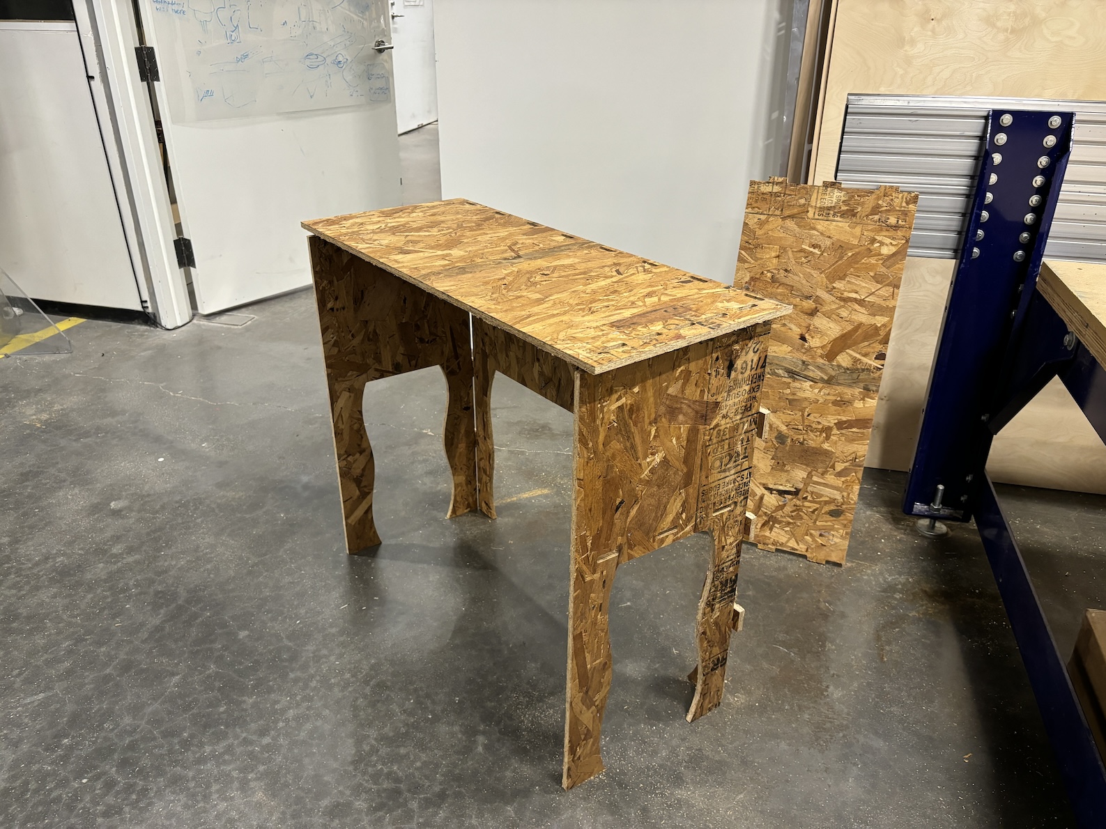
The final product - an incomplete table due to challenges above
Video of the final product