How to Make (almost) Anything 2023 | Final Project
Home
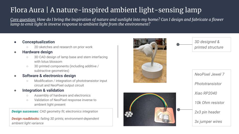
Flora Aura: A nature-inspired ambient light-sensing lamp
---
Primary files:
- Phototransistor & NeoPixel Jewel 7 PCB schematic and design; referenced in referenced in Week9.1 (KiCad)
- Lamp base CAD (Fusion360)
- Lamp stem CAD (Fusion360) (note: view is currently sliced to provide the STL of a half-stem for ease of 3D printing)
- Lotus blossom STL converted to CAD model (Fusion360; source: opensource Thingiverse - "Lotus Flower Lamp" by mled90)
- Arduino program to power lamp functionality (Arduino IDE; Code modified from The Arduino Workshop and Adafruit Library)
Summary overview of the Flora Aura project
---
Final project key questions:
What does it do?
Flower-shaped lamp which turns on in inverse response to the presence of ambient light; Perfect to bring the calming presence of nature and bright sunlight as we head into daylight savings.
Who's done what beforehand?
Inspiration was found from public projects that referenced a mechanical tulip lamp (JiriPraus), along with a large-scale version from a previous HTMAA class (Nadieh Bremer). Additionally, I found inspiration for the individual components of the electionics system, finding resources for both a phototransistor circuit (The Arduino Workshop) and neopixel circuit (Adafruit Library); I was able to use the opensource Lotus STL for the intricate geometries of the flower blossom ("Lotus Flower Lamp" by mled90).
What did you design?
- 2D design of lamp concept
- 3D CAD design / print of lamp base and stem interfacing with lotus blossom
- Modification / integration of phototransistor input circuit and Neopixel output circuit
- Integration / assembly of hardware and electronics
What materials and components were used? Where did they come from? How much did they cost?
Materials:
- (1) NeoPixel Jewel 7 (~$6)
- (1) Phototransistor visible light (~$0.40)
- (1) 10K Ohm resistor (~$0.10)
- (1) Seeed Studio Xiao RP2040 (~$5)
- (1) 2x3 pin header (~$0.70)
- (3) Male:Female jumper wires (~$2/20 pack; ~$0.10/unit)
- (1) PCB milling stock: FR-1 4"x5" printed circuit board blanks (~$40/25 pack; ~$1.6/unit)
- White PLA filament (~$25)
Tools:
- Prusa MK3 3D printer (~$900)
- Soldering iron (~$40)
- Solder wire (~$32)
- LUNYEE 3018 pro max all-metal 500W CNC router machine (~$380); excluding accessories)
- Fusion360 (free with education license)
- Prusa Slicer (opensource)
What parts and systems were made?
- 3D printed lotus blossom
- 3D printed lamp base
- 3D printed lamp stem (printed as two halves)
- PCB containing phototransistor and NeoPixel
- Arduino IDE program loaeded onto PCB to execute light response
What processes were used?
- 2D sketching and conceptualization
- 3D CAD in Fusion360
- 3D printing on Pursa MK3
- Electronics design in KiCad
- PCB production on CNC milling machine and soldering components
- Electronics programming written in Arduino IDE
What questions were answered?
Can I design and fabricate a desk lamp that turns on automatically based on ambient light levels?
What worked?
Success in CAD geometries aligning when 3D printed; Successful integration of phototransistor and NeoPixel with minor debugging help from Dave & Quentin!
What didn't?
Major setbacks experienced with failed 3D prints and machine shortages; Weight considerations also came into play when deciding to pursue future spirals / designs, ultimately finding that 3D printing all material was a more effective solution for the current design; Variability in ambient light within an environment also became a challenge, but could be manually adjusted via the sensitivity variable (boost) included in the Arduino program.
How was it evaluated?
Validation of phototransistor providing accurate light sensor values, NeoPixels lighting up as expected, and full assembley responding by turning on NeoPixels in inverse response to ambient light presence.
What are the implications?
This lamp demonstrates the ability for input and output sensors to interact with one another and provides the user feedback about their environment; While this lamp can be standalone in its current stage, there is an option to pursue future spirals to scale the lamp larger and add actuating systems.
---
Procedure:
Initial conception & workplanning:
- Begin the process with initial brainstorming and 2D sketching of a potential solution
- Conduct preliminary research to draw from inspiration of existing projects
- Map out a spiral design approach for achieving, and building upon, the end goal in stages (see 'Archive' section below)
Electronics design & production:
- Identify the compartamentalized circuitry components: input phototransistor sensor, output NeoPixel Jewel 7 illumination
- Design, produce, and validate the input phototransistor sensor in Week 9.1
- Design, produce, and validate the output NeoPixel Jewel 7 device in Week 10.1
- After both systems have been validated independently, create a program in Arduino IDE to integrate the two devices such that the output is dependent on the input value (see 'Arduino program to power lamp functionality' file listed at top of page)
- Validate the program provides the desired outcomes and adjust the parameters as desired for the given ambient light environment
Hardware design & production:
- Initial structural design considerations were planned in a spiral approach to become increasingly complex with actuations across multiple components, however, several design considerations played into deciding a path of reduced complexity
- Due to time limitations particularly given a number of 3D printers that were down in the fleet, the process was streamlined to one flower component given the multi-hour print process and high demand for 3D printers
- The scale of the lamp was also influenced by the 3D printers, and as such the design was constrained to a small desk lamp given print time and availble bed space on the printer
- Further material testing of the lamp stem component revealed that the initial considerations of a flexible lamp stem via welding rod or repurposing a traditional desk lamp neck revealed these material may not be the most conducive for balancing the weight of a small lamp (i.e., utilizing the bulky, taditional metal lamp neck) or for providing an optimal user experience (i.e., the welding rod has limited flexiblity over time as it harders with multiple bends); This material assessment led to the decision to 3D print the lamp stem in addition to the lamp head and base
- Preliminary research guided me to an opensource lotus-shaped lamp head (see 'Lotus blossom STL converted to CAD model' at top of page), which I then designed the remainder of the lamp around to complement the geometries
- Within Fusion360, I designed the base of the lamp by sketching and extruding a circle to form a shape similar to a hockey puck
- Another sketch of a slightly smaller circle was created and cut from the inside of the hockey puck to create a hollow bottom
- On the side of the base, an arc was drawn and cut so there would be an access point for the user to connect to the PCB
- A small circle was cut out from the top of the base, in-line with the arc opening to allow the ambient light a more direct path to the phototransistor that would be housed below
- A circle the desired inner diameter of the lamp stem was cut from the center of the top of the base, with another slightly wider circle comparable to the outer diameter of the desired lamp stem cut at a shallower depth to create a secure step for the lamp stem to rest within the base
- A bottom plate was created to encolse the electronics by sketching a circle of equivalent size as the original base, but extruing ~5mm as a separate body; This will be secured to the bottom of the base as a final step to package the lamp after the electronics have been installed
- Create the lamp stem by sketching a spline of the desired geometry through the center of the lamp base, then select hollow pipe for extrusion
- Upon completion of the CAD model (see 'Lamp base CAD,'Lamp stem CAD,' and 'Lotus blossom STL converted to CAD model' listed at the top of page), a small scale draft 3D print was created to validate the integration of geometries across the parts
- Note that for printing purposes, the stem was printed as two halves that would press-fit together during assembly to allow for the printer to effectively produce the hollow inside; Additionally, it was found helpful to add a brim to the print to stabalize the parts
- Unfortunately there were limited 3D printers availble for use as many were breaking down this week, so this process was delayed after a series of failed prints; However, upon validation of the printed draft model, I was pleasantly surprised that the press-fit geometries worked well together, with only slight modifications to the base to allow additional light to the sensor (initially assumed the concentrated hole of light would help eliminate noise of the lamp light, but found the sensor was still a bit too sheilded by the base cover)
- In order to allow for additional light to reach the phototransistor, 3 additional small holes were added along the top edge of the base by the arch opening; The sensor responded well to this revised base
- The final print of the lamp structure was at the scale of base 60%, stem 60%, and lotus 45%
Integration:
- After completion of the final print of the lamp structure, the electronics were encased inside
- For this process, the jumper wires attached to the NeoPixel Jewel 7 were threaded through the opening of the lotus, and then aligned with the open half of one side of the stem
- The jumper cables were then enclosed by the other half of the stem, and the free ends were threaded one at a time through the top opening of the lamp base
- The end of the stem was then wedged into the slot of the same center opening in the base
- Upon securing the stem, the opening of the lotud head was pressed into place around the stem
- The PCB was placed underneath the base and the jumper wires were connected to their respective pin heads
- With the PCB in place, the bottom enclosure was secured to package the electronics for easier transport
- The Xiao RP2040 was connected to the laptop and loaded with the Arduino program outlined in the 'Electronics' section
- Upon running the program, it became evident that the sensitivity associated with boosting the phototransistor signal needed to be calibrated across different rooms and environments, given the variability in brightness of ambient light present
- The sensitivity value was adjusted and the lamp was validated in multiple settings that the NeoPixel responded as anticipated
---
Electronics design & production:
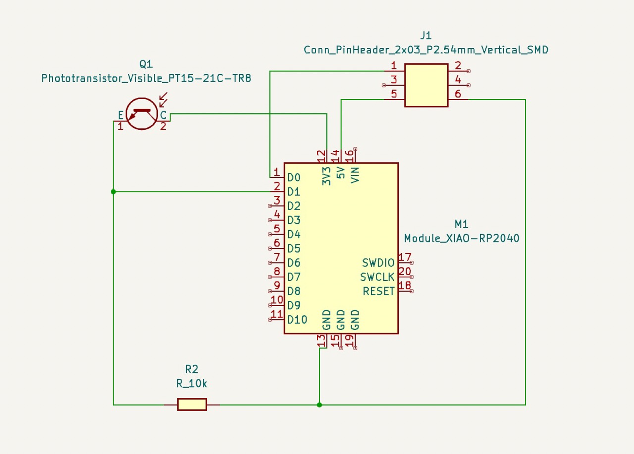
Phototransistor and NeoPixel Jewel 7 PCB schematic in KiCad; referenced in Week 9.1
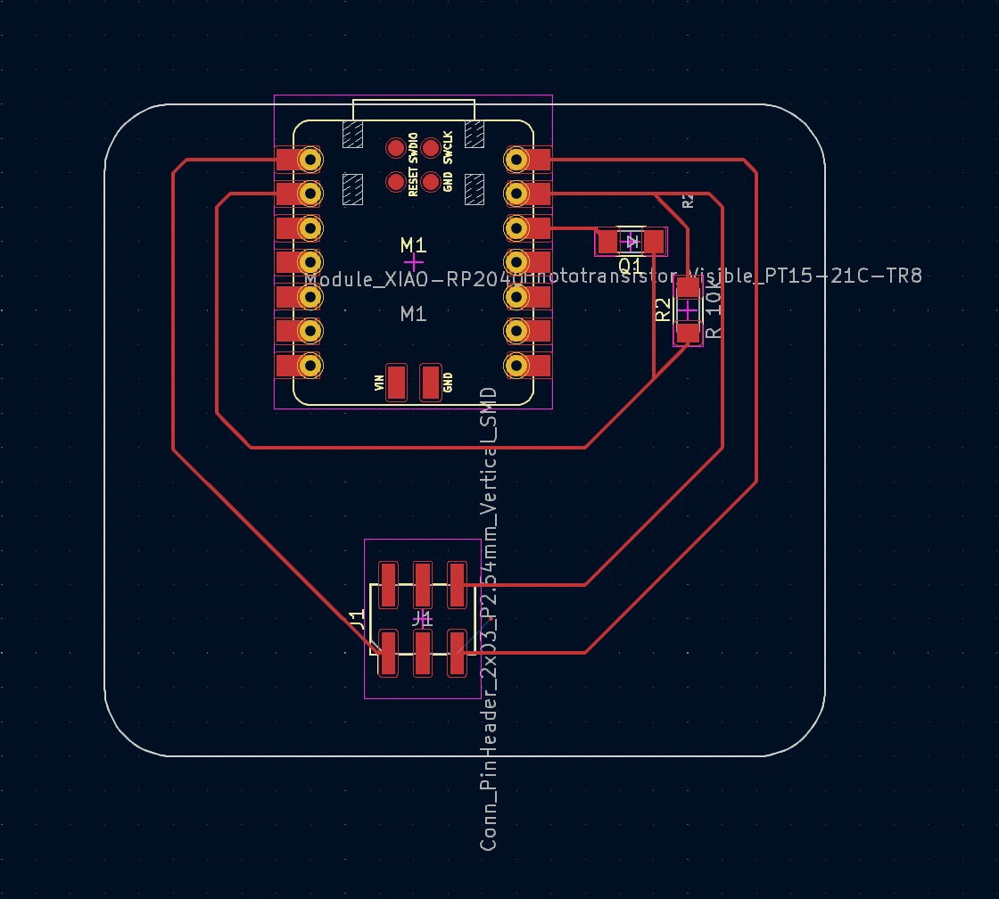
Phototransistor and NeoPixel Jewel 7 PCB design in KiCad; referenced in Week 9.1
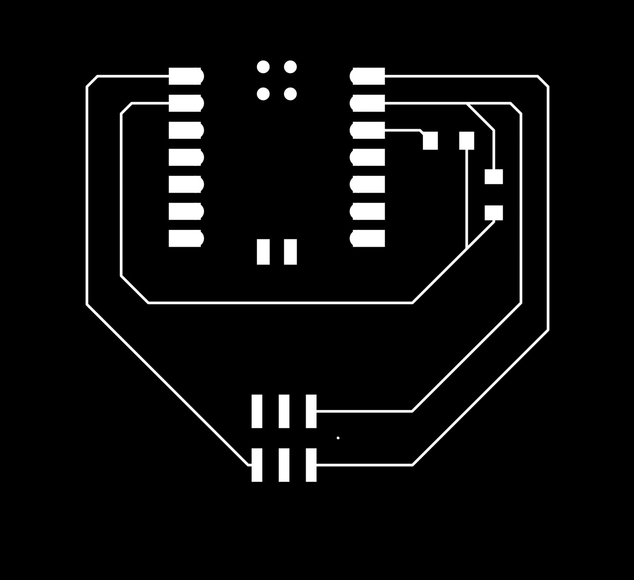
Phototransistor and NeoPixel Jewel 7 PCB trace footprint; referenced in Week 9.1
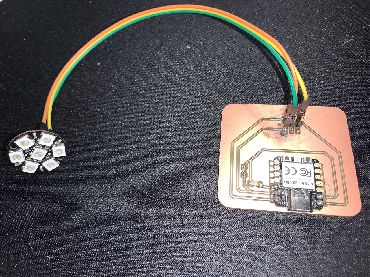
Phototransistor and NeoPixel Jewel 7 PCB circuit; referenced in Week 10.1
Hardware design & production:
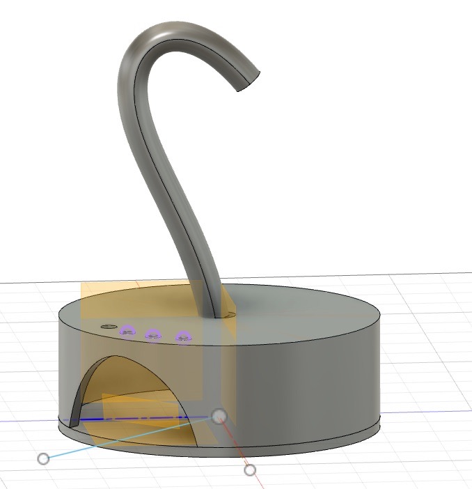
Flora Aura CAD moceling process of base and stem to integrate with the lotus blossom and house electronics
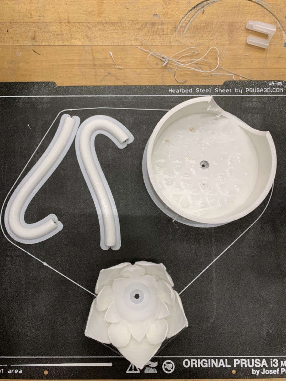
3D printing process of the lamp components, after many failed prints due to technical difficulties with the printer fleet
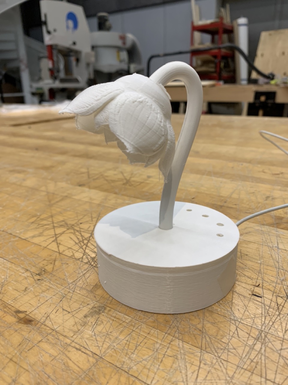
Assembled Flora Aura 3D printed structure via press-fit components
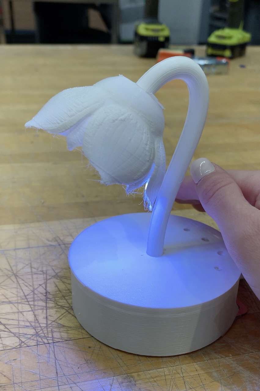
Validation of Flora Aura's response to reduced ambient light, which actuates the NeoPixel Jewel 7 illumination
---Archive of preliminary workplan---
Initial concept: A floral lamp inspired by nature, using light-activated moving flower petals to control the light emitted as an inverse of the natural sunlight present.
Spiral design workplan:
Throughout the course of development and material testing, there was a decision to stop after spiral1 and focus more on the 3D printed geometries given their light-weight structure compared to an actuating stem or petal system.
Spiral 0:
- Develop standalone light-sensing input circuit
- Develop standalone neopixel output circuit
Spiral 1:
- Develop light-sensing circuit that controls neopixel output
- Design and 3D print stationary flower and base (without stem or petal actuator system)
Spiral 2:
- Develop light-sensing circuit that controls neopixel output and servo motor
- Design and 3D print single actuating flower and base (includes stem and petal actuator system)
Spiral 3:
- Expand Spiral 2 design across three actuating flowers
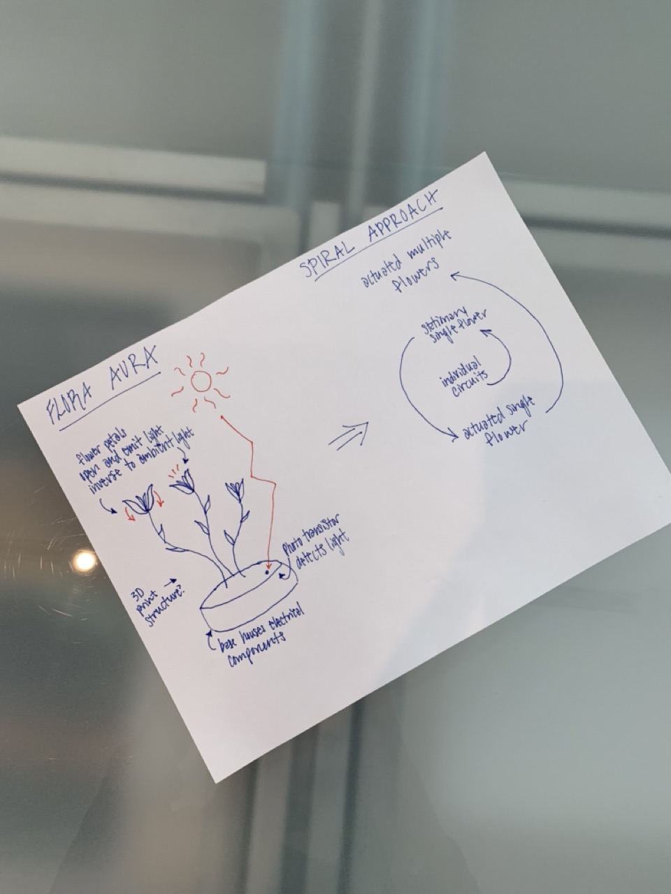
2D sketch of Flora Aura concept and spiral-design approach