![[Profile Image Placeholder]](profile.jpg)
Week 8
Output Devices
Week Highlights
Key captures from the group and individual assignments with links to their sections.
Table of Contents
Course Content
Training & Documentation
Assignments & Projects
Output Devices
This week focuses on exploring various output devices and actuators that can be integrated with microcontroller boards. We'll learn about different actuator types, power management, and how to control output devices effectively.
This Week's Goals
- Explore Output Device Types
Learn about LEDs, displays, motors, servos, steppers, speakers, and other actuators - Power Management
Understand current limiting, voltage regulation, and power consumption measurement - Implementation
Add output devices to microcontroller boards and successfully control them
Assignments
- Group Assignment
Measure the power consumption of an output device - Individual Assignment
Add an output device to a microcontroller board you've designed, and program it to do something
Tools & Materials
- Microcontroller Boards
- Output Devices (LEDs, displays, motors)
- Power Supply
- Joulescope Energy Analyzer
- Multimeter
Training Documentation
Training materials and documentation for output devices and multi-axis machining.
Multi-Axis Machining
How to multi-axis mill (almost) anything. Understanding the capabilities and limitations of 3-axis and 5-axis machining for complex part fabrication.
Reference Materials
Philosophy
Human fabrication techniques are inherently more 5-axis than 3-axis—consider using a Dremel to carve a pumpkin. Additional axes are decreasing in cost, making 5-axis machining increasingly accessible. Modern 5-axis machines (e.g., UMC series) now cost around $100k USD, similar to robotic arms with 3–6 degrees of freedom.
3-Axis Machining
3-axis machining removes material through shearing. The load is applied to a bending beam from spindle to tool, where the rake angle determines tool sharpness and cutting efficiency.
Feed (inches per tooth, IPT) and surface speed (SFM) determine the processing window, balancing:
- Tool breakage (high feed) — above maximum force
- Overheating (high feed/high speed) — above maximum heat load
- Chatter (high feed/low speed) — vibration instability
- Rubbing (low feed) — below minimum cutting force
- Buildup/edge formation (low speed) — material adhesion
Workholding options include clamping, vacuum, adhesives, electrostatic, and magnetic methods. Roughing removes material quickly (can take up to 3 hours), limited by moving the part relative to the machine. Parts need to cool, and thermal expansion must be accounted for. The most accurate approach uses the largest tool that fits, not the smallest. Endmill entry is not flat (helical entry into material), and extra stock is used to account for beam bending of the endmill.
Roughing strategies use adaptive/pocket clearing with simulated stepdowns to balance time vs. inconsistencies. Maximum roughing time should be limited to ~30 minutes before moving on. Surfacing creates surface finishes using toolpath options: steep/shallow, scallop, or contour (you can bound the tool to specific areas in Fusion 360). Larger endmills are faster for surfacing operations.
Multi-Axis (5-Axis) Machining
5-axis machining enables reaching and positioning tools, repositioning workpieces for time and accuracy (without manual intervention), and improved surface finishing. The system is always limited by contact at every point in space.
There are two main approaches:
- 3+2 machining — repositioning then 3-axis cutting
- Simultaneous 5-axis — moving more than 3 axes at once, including advanced swarf, multi-axis contour (perpendicular to surface), or multi-axis finishing with ball mills or circle-shaped end mills
Limitations include CAM software processing speed (single-threaded operations), complexity of simulating tool movement relative to workholding and part interference, and managing remaining stock (Fusion 360) or rest material (Mastercam).
Understanding machine kinematics is critical—see the MAS.865 mechanical design resources for detailed analysis of how machines move in space.
Flexibility
With 5-axis capability, the distinction between mills and lathes becomes blurred. Mills hold the workpiece while the tool spins; lathes hold the tool stationary while spinning the workpiece. This flexibility reduces design limitations. Think of systems in terms of three components: the tool, workholding, and axes.
Tools: extrusion nozzles, grinding spindles, regular spindles, ultrasonic spindles (for glass), friction stir welding tools, knives, pizza cutters, hole punchers
Axes: different spindle configurations, different head designs
Summary
3-axis and 5-axis machining each have their place. The key is understanding which to use when, and how 5-axis capability breaks down barriers between traditional tool classifications, enabling more flexible and creative fabrication approaches.
Useful Documentation
Essential resources for output devices and actuator integration.
Class Page
Comprehensive resource covering all output device categories including LEDs, displays (LCD, OLED, TFT), motors (DC, stepper, servo, brushless), speakers, solenoids, and more. Includes detailed tutorials, code examples, and implementation guides for various output device types.
Group Assignment: Measuring Power Consumption of Output Devices
Measuring power consumption of motors, servos, and stepper motors using adjustable power supplies and precision energy analyzers to understand performance characteristics and when to use each type.
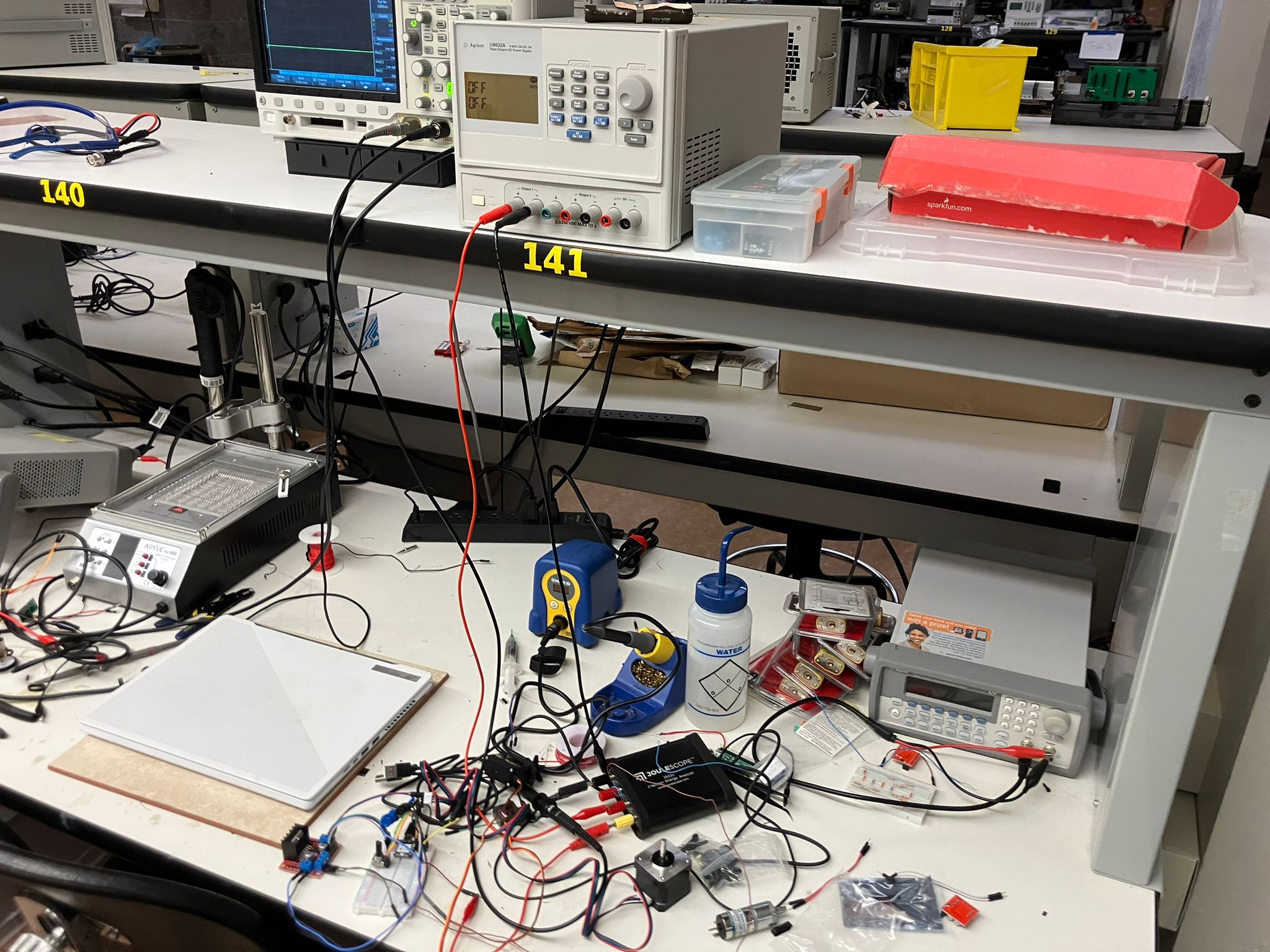
Measurement Setup
We used an adjustable power supply set to 15V and measured quiescent power consumption of 450 mW (0.03 A, where P=IV) before connecting any motors. Power measurements were conducted using the Joulescope (JS220) Precision Energy Analyzer to measure current, voltage, power, charge, and energy in real-time.
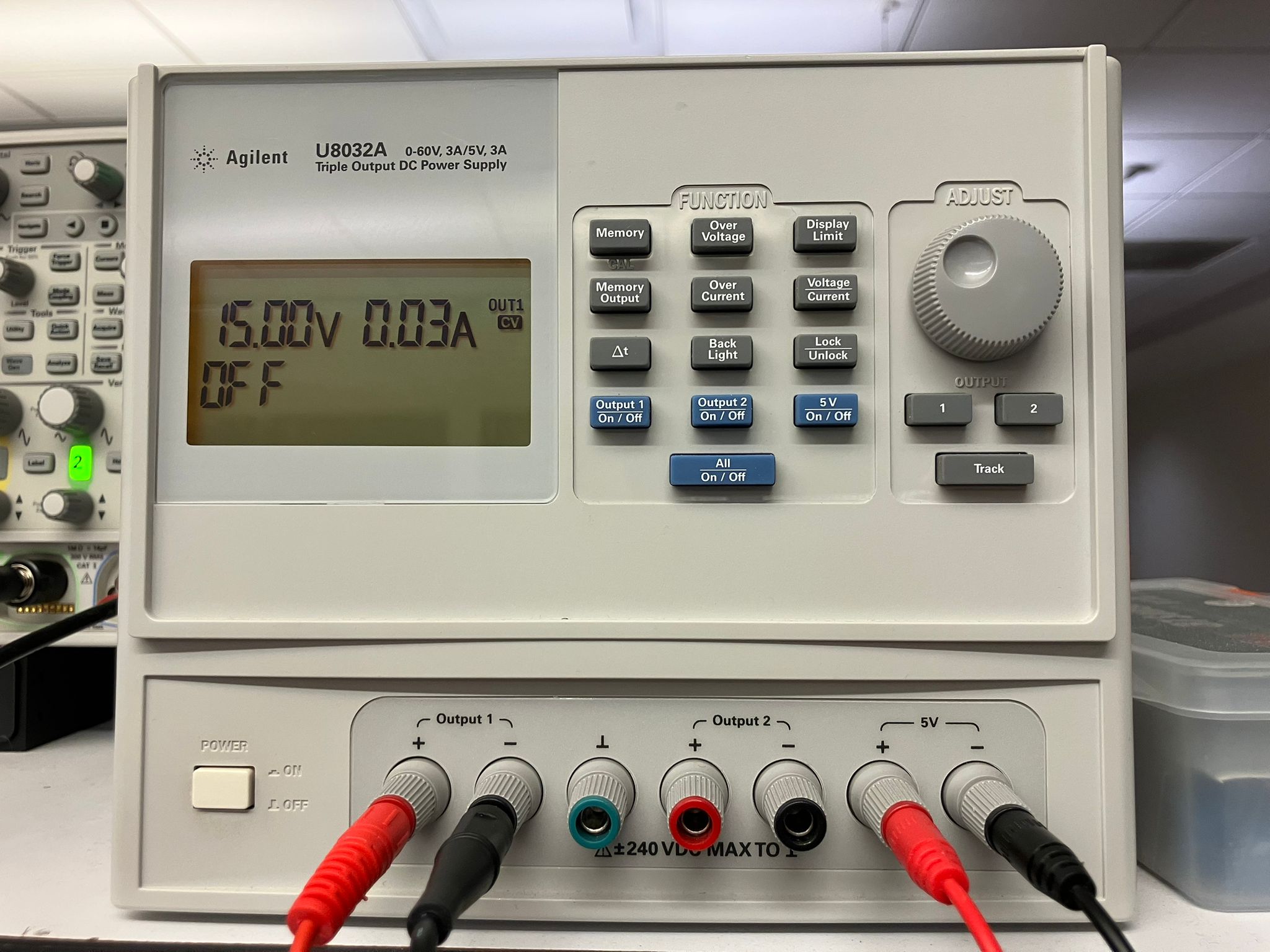
Power supply set to 15V for motor testing
Joulescope JS220 Precision Energy Analyzer
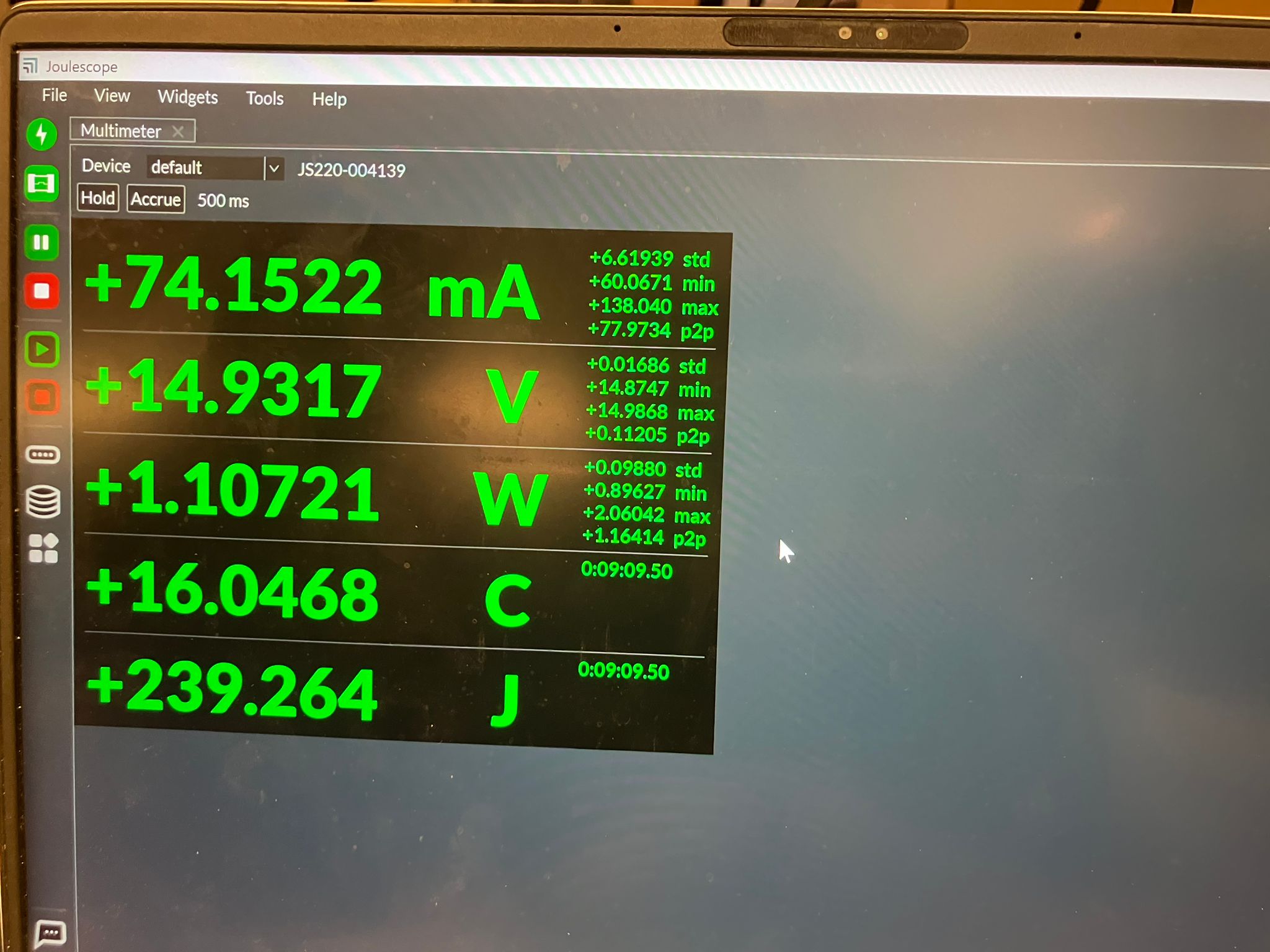
Joulescope software interface
Using a potentiometer to change motor speed, we observed that below a certain threshold, the motor doesn't have enough power to spin (no mechanical work, just electrical losses). Above this threshold, speed increases with power. The dI/dt (rate of current change) cannot change instantly—it takes time. The PWM signal from the microcontroller (roughly 50% duty cycle) is smoothed after passing through the motor driver, with more linear behavior on the rising edge than the falling edge.
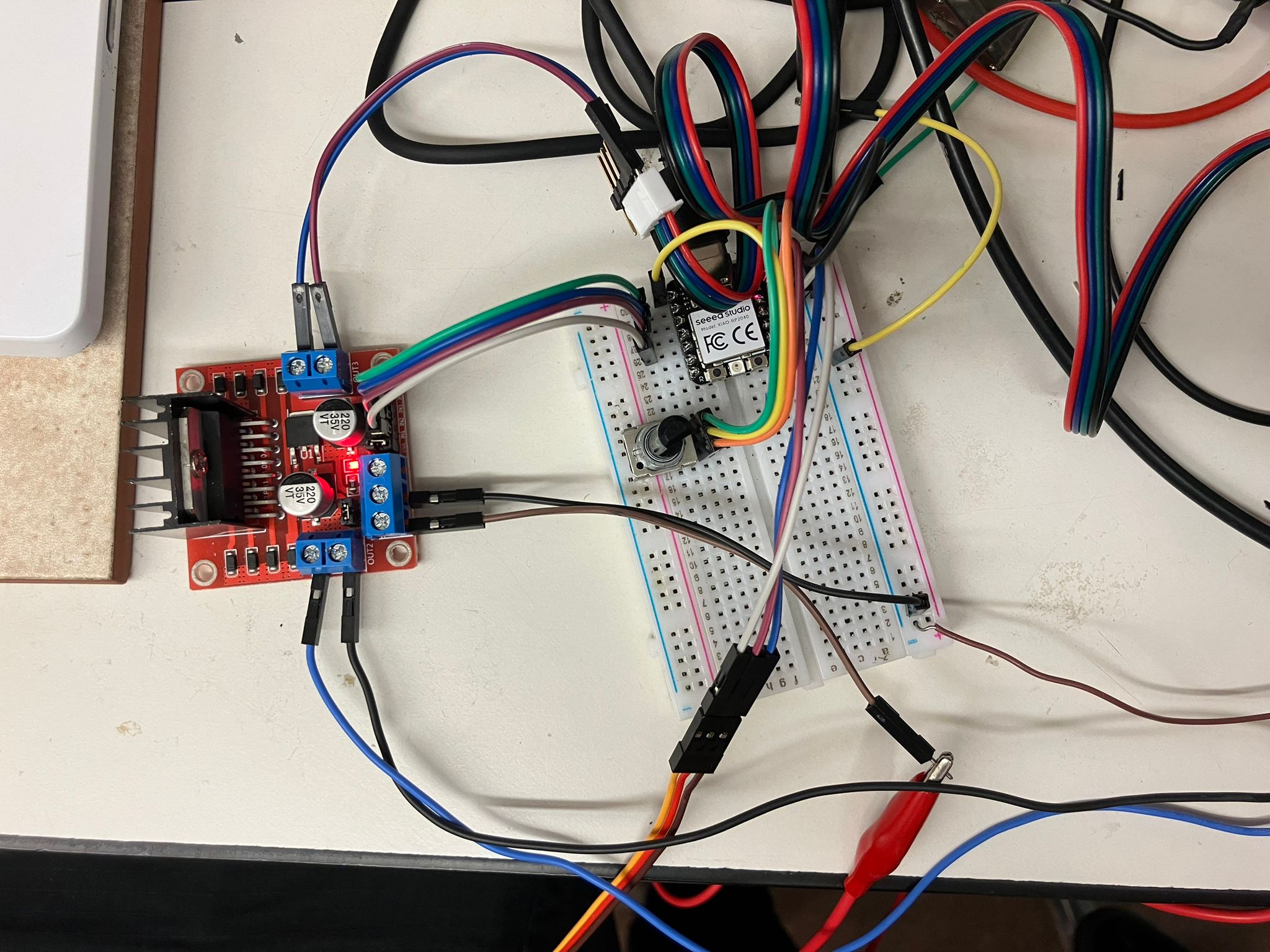
Motor circuit connections
Complete motor testing setup
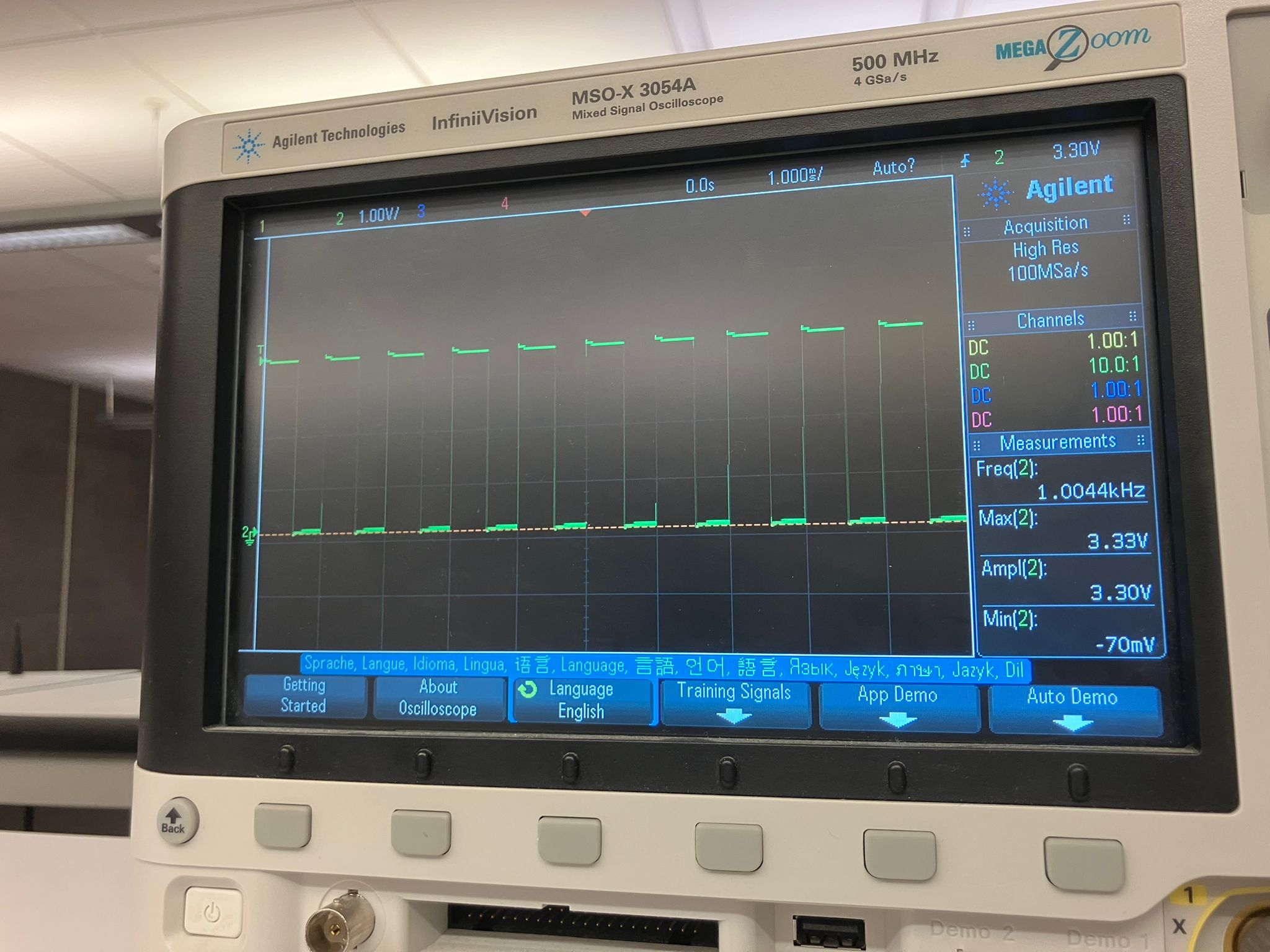
50% duty cycle PWM from microcontroller
Smoothed PWM signal after motor driver
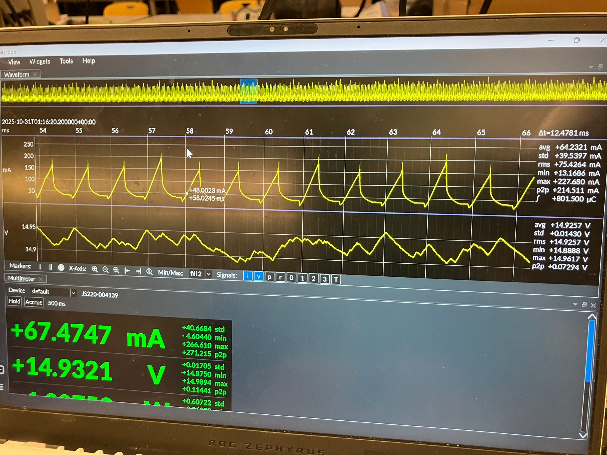
Zoomed-in power measurement
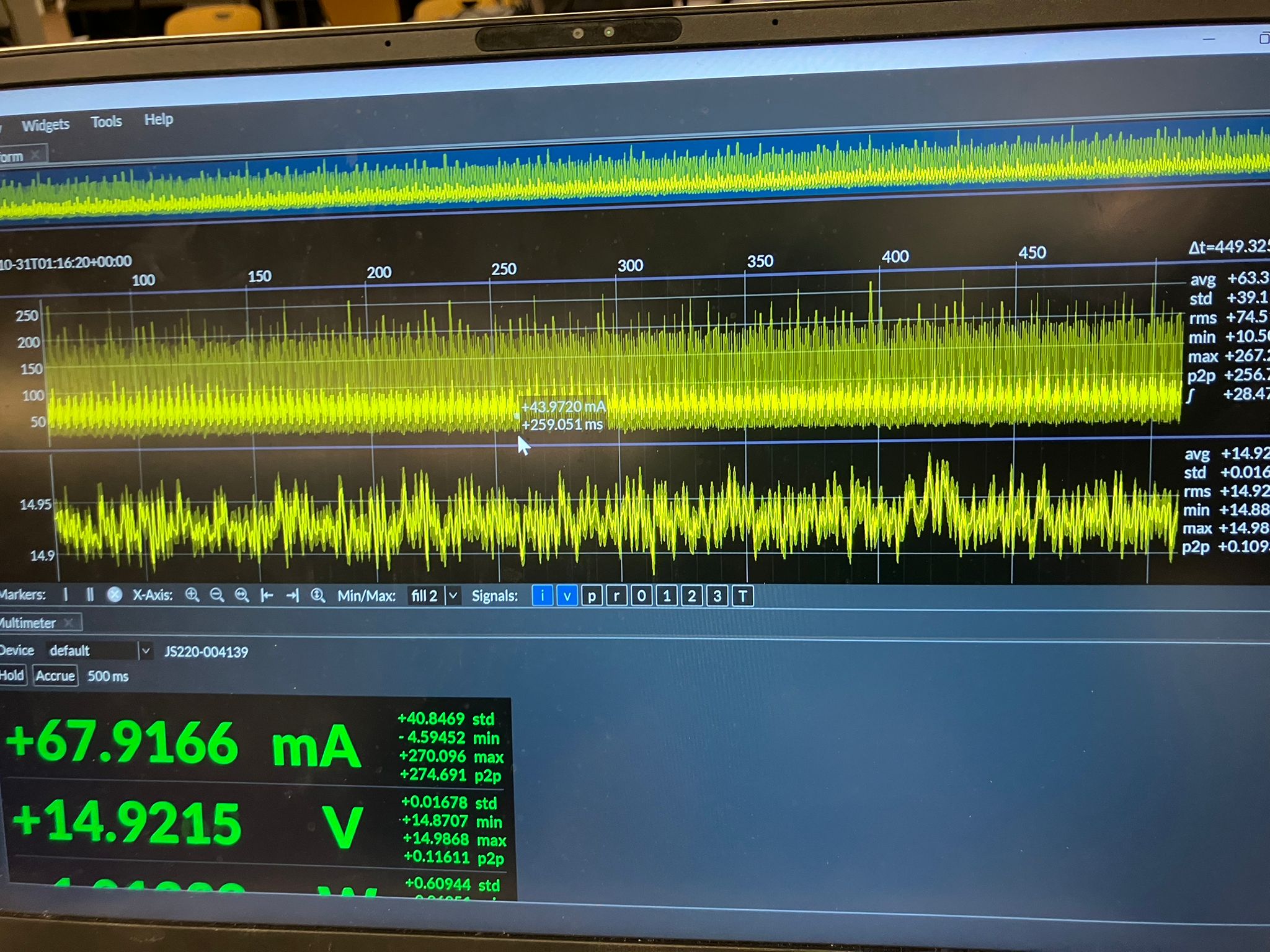
Zoomed-out power measurement
Motor Comparison Results
All motors tested at 15V supply, 2A current limit, with the same potentiometer value for comparison. The potentiometer determines speed and power for DC motors, and position for servos.
DC Motors (Voltage-Controlled)
DC Brushed Motor (Large)
Characteristics: Low-speed, high torque, no positional control
- Current: 57 mA
- Voltage: 14.49 V
- Power: 0.8 W
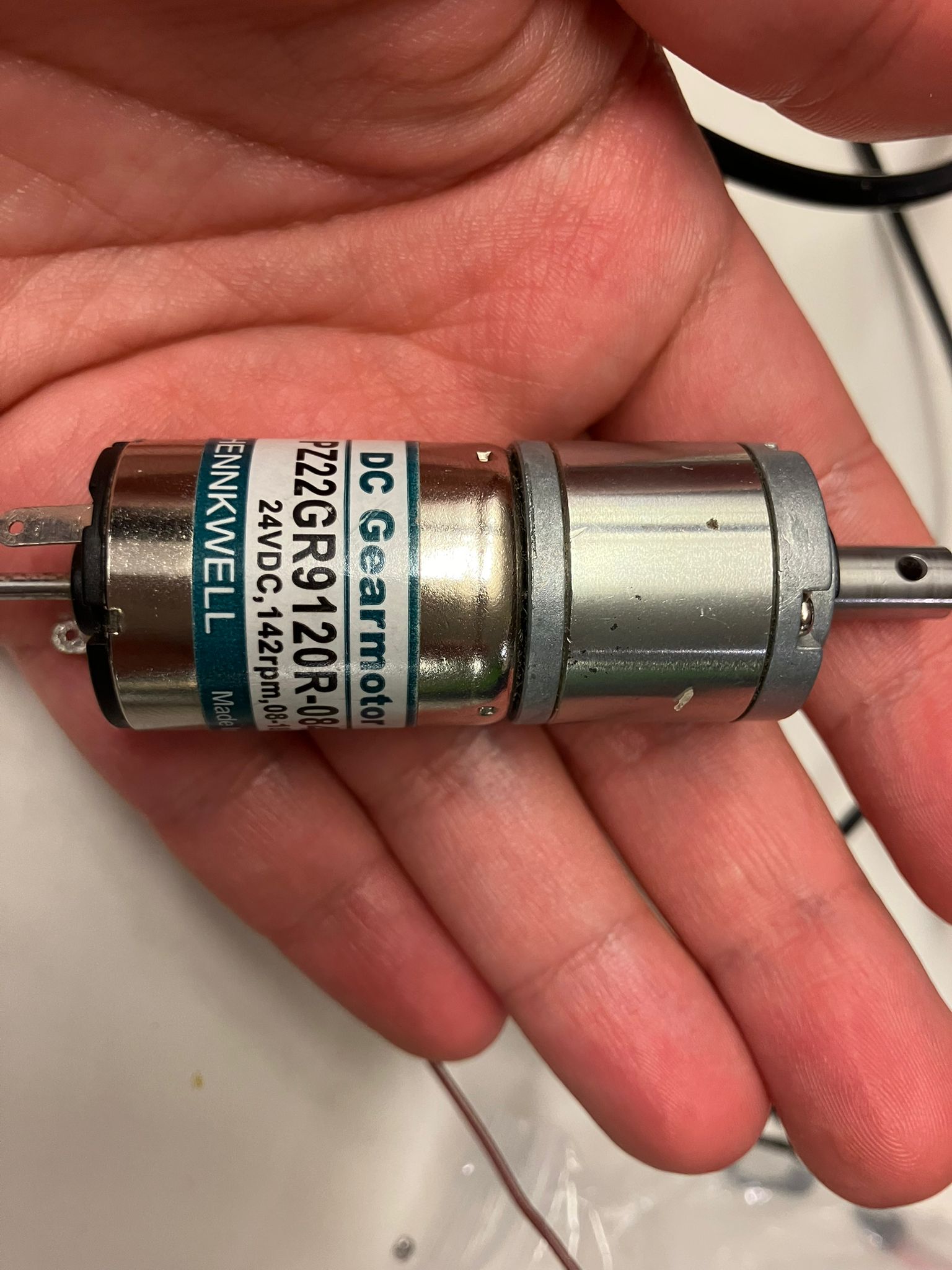
Large DC brushed motor measurement
DC Brushed Motor (Small)
Characteristics: High speed, medium torque, no positional control
- Current: 0.34 A
- Voltage: 14.47 V
- Power: 4.86 W
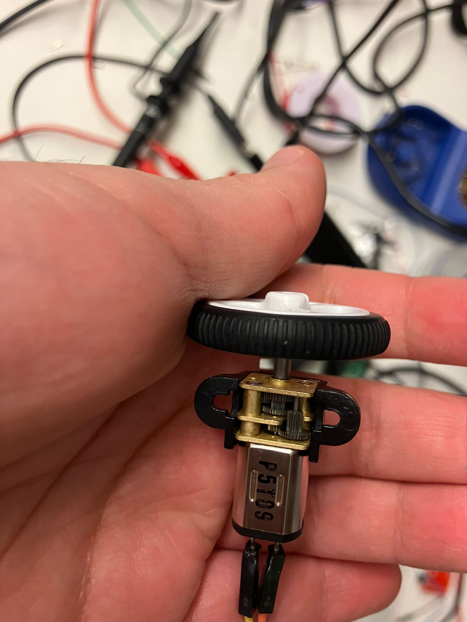
Small DC brushed motor measurement and operation
DC Stepper Motor (Current-Controlled)
Characteristics: Medium speed, medium torque, zero absolute positional control (relative positioning only)
- Current: 2.0 A
- Voltage: 10.93 V
- Power: 22.33 W
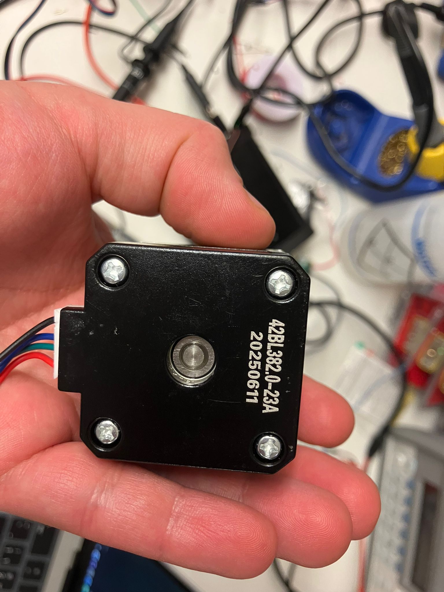
Stepper motor measurement and operation
Servo Motors (5V Supply, Position-Controlled)
All servos tested at 5V supply, 2A current limit. Potentiometer determines position; power consumption remains relatively constant.
Servo Motor (Large)
Characteristics: Absolute positional control, slower response
- Current: 10.6 mA
- Voltage: 4.99 V
- Power: 53.4 mW
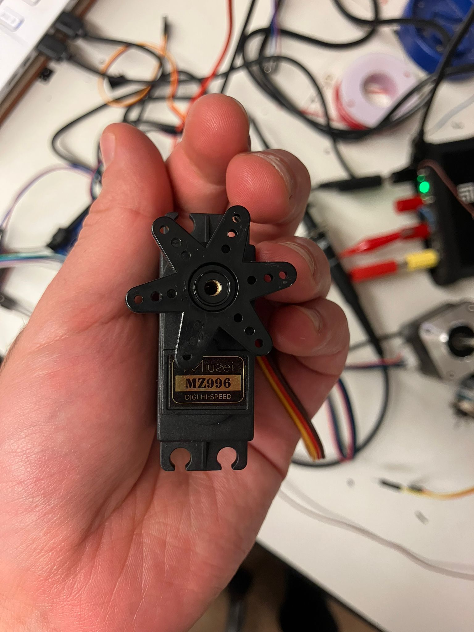
Large servo motor measurement
Servo Motor (Micro)
Characteristics: Absolute positional control, slower response, lower power
- Current: 5.04 mA
- Voltage: 4.99 V
- Power: 25.05 mW
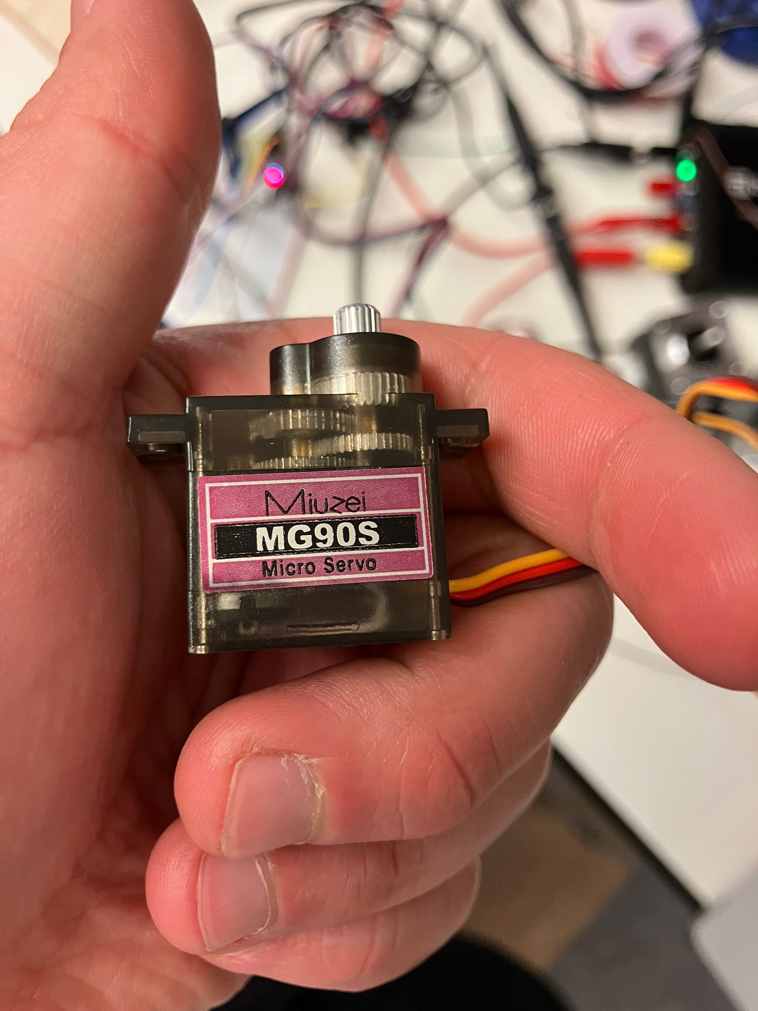
Micro servo motor measurement
Motor Comparison Summary Tables
Constant Voltage Comparison (15V Supply, 2A Current Limit)
DC brushed and stepper motors tested at 15V. Potentiometer controls speed for brushed motors, and step rate for stepper motor.
| Motor Type | Size | Current | Voltage | Power | Characteristics |
|---|---|---|---|---|---|
| DC Brushed | Large | 57 mA | 14.49 V | 0.8 W | Low-speed, high torque, no positional control |
| DC Brushed | Small | 0.34 A | 14.47 V | 4.86 W | High speed, medium torque, no positional control |
| Stepper | N/A | 2.0 A | 10.93 V | 22.33 W | Medium speed, medium torque, relative positioning only |
Constant Current Comparison (5V Supply, 2A Current Limit)
Servo motors tested at 5V. Potentiometer controls position; power consumption remains relatively constant regardless of position.
| Motor Type | Size | Current | Voltage | Power | Characteristics |
|---|---|---|---|---|---|
| Servo | Large | 10.6 mA | 4.99 V | 53.4 mW | Absolute positional control, slower response |
| Servo | Micro | 5.04 mA | 4.99 V | 25.05 mW | Absolute positional control, slower response, lower power |
Summary: When to Use Each Motor Type
- DC Brushed Motors: Simple applications requiring variable speed and torque, where positional control is not needed
- Stepper Motors: Applications requiring precise relative positioning with medium power consumption
- Servo Motors: Applications requiring absolute positional control with low power consumption, especially in battery-powered systems
Individual Assignment: Output Devices
Adding simple and complex output devices to the custom development board designed in Week 4, including a bright LED and OLED display for sensor visualization.
Related Documentation
- PCB Design (Week 4) — Development board design with ESP32S3
- PCB Production (Week 5) — Board fabrication and assembly
- Input Device: LED Button (Week 7) — Simple input device implementation
- Input Device: Camera Edge AI (Week 7) — Complex input device with edge AI inference
Simple Output Device: Bright LED
Implementing a bright LED output using the MP-3014-1100-50-80 from the Fab Lab inventory. This high-power LED requires careful current limiting to achieve maximum brightness while maintaining safe operating conditions.
Current Limiting Resistor Calculation
For maximum brightness, we calculated the current limiting resistor for a 3.3 V supply driving an LED with a forward voltage (Vf) of 2.85 V. Using a 5 Ω resistor (the smallest available in the shop):
Step-by-Step Calculation
Step 1: Voltage across resistor
VR = Vsupply - Vf = 3.3 V - 2.85 V = 0.45 V
Step 2: LED current
I = VR / R = 0.45 V / 5 Ω = 0.09 A = 90 mA
Step 3: Resistor power dissipation
PR = VR × I = 0.45 V × 0.09 A = 0.0405 W
Step 4: LED power dissipation
PLED = Vf × I = 2.85 V × 0.09 A = 0.2565 W
Result: At 3.3 V with a 5 Ω resistor, the LED draws approximately 90 mA, which is well below the 150 mA maximum rating. This provides slightly reduced brightness compared to maximum, but significantly extends lifespan and reduces heat generation.
| Resistor (Ω) | LED Current (mA) | Power in Resistor (W) | Notes |
|---|---|---|---|
| 3.0 Ω | 150 mA | 0.0675 W | Max brightness, close to rated max current (hot) |
| 3.9 Ω | ~115–120 mA | ~0.055 W | Good balance: bright but less stress |
| 4.5 Ω | ~100 mA | ~0.045 W | Cooler, longer life |
| 5.0 Ω | ~90 mA | ~0.0405 W | Selected: even cooler, ~0.26 W in LED, very safe thermally |
Bright LED test demonstration
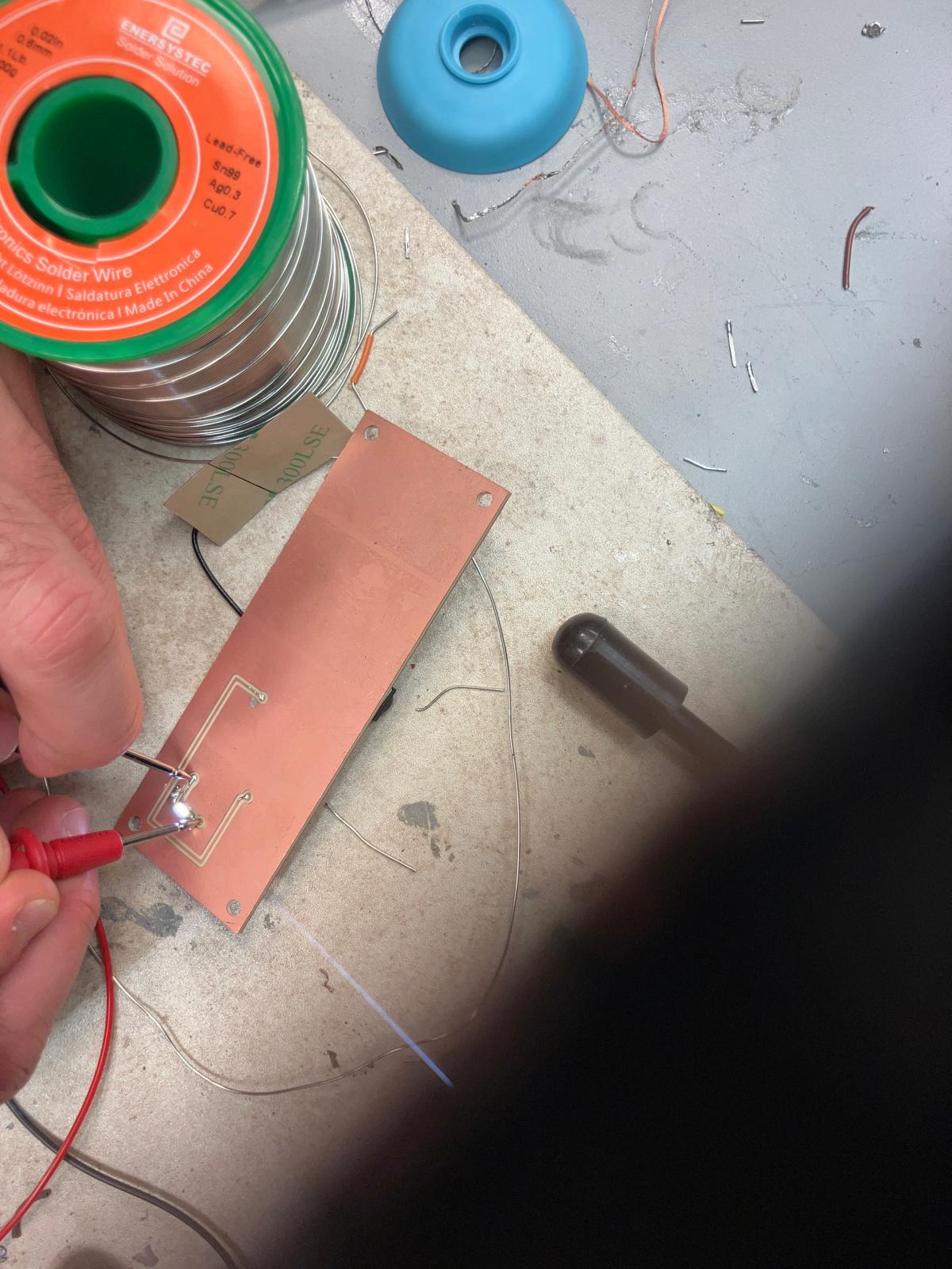
Bright LED circuit on development board
Complex Output Device: OLED Display
Implementing an SSD1306 OLED display for visualizing sensor data. The I²C interface requires two 10 kΩ pull-up resistors—one between 3.3 V and SDA, and one between 3.3 V and SCL. These were soldered onto the connectors of the development board to enable proper I²C communication, which was previously failing in earlier weeks without these pull-up resistors.
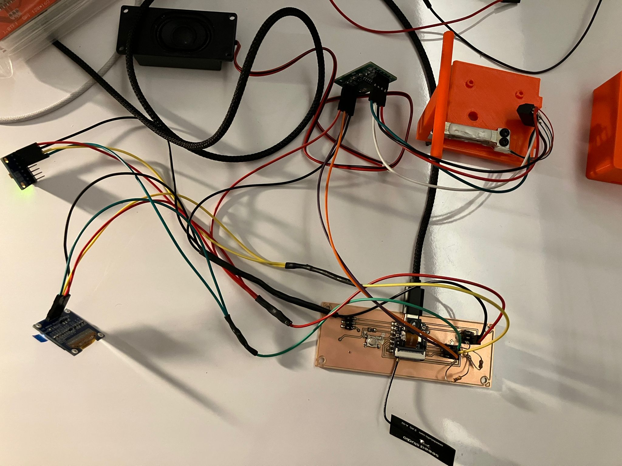
Development board with OLED display connected, showing pull-up resistors soldered to I²C connectors
Standard OLED connections: VCC to 3.3 V on ESP32S3, GND to GND, SDA to SDA (pin 5), and SCL to SCL (pin 6).
Accelerometer Data Display
Displaying real-time accelerometer data from the MPU6050 sensor on the OLED screen. This implementation required working SDA and SCL connections with proper pull-up resistors, which were finally fixed this week after troubleshooting I²C communication issues.
Accelerometer data displayed on OLED screen showing acceleration and gyroscope values
Camera Output Display
Displaying camera capture output on the OLED screen with Edge AI inference results. SDA and SCL were not working in previous weeks without the pull-up resistors. While troubleshooting, camera output was verified through the serial monitor, and the input device functionality was confirmed by testing on Quentin's board. With the pull-up resistors now in place, the OLED display successfully shows camera frames and inference results.
Camera output with Edge AI inference displayed on OLED screen showing TTD (time-to-death) prediction
Design Files
Complete design files for sensors display and camera dev board implementations including Arduino firmware and configuration files.
Sensors Display Code
The sensors display script reads data from multiple sensors (MPU6050 accelerometer/gyroscope and HX711 load cell) and displays the values on both the OLED screen and Serial Monitor. The system activates data collection when a button is pressed.
How It Works (Pseudocode):
BEGIN Setup
  Initialize Serial communication (115200 baud)
  Configure button pin (INPUT_PULLUP) and LED pin (OUTPUT)
  Initialize I2C bus (SDA=5, SCL=6) at 100kHz
  Initialize OLED display (SSD1306, 128x64, I2C address 0x3C)
  Initialize MPU6050 accelerometer/gyroscope (try 0x68, then 0x69)
  Initialize HX711 load cell amplifier
  Set calibration factor and tare (zero) the scale
  Display "Setup complete!" message on OLED
END Setup

BEGIN Loop
  Read button state

  IF button pressed THEN
    Turn LED ON

    IF not already collecting THEN
      Start data collection mode
      Print "=== START DATA COLLECTION ===" to Serial
    ENDIF

    IF 500ms have passed since last read THEN
      Read accelerometer/gyroscope data (acceleration x,y,z, gyro x,y,z, temperature)
      Read load cell data (raw value and weight in grams)

      Print all sensor values to Serial Monitor

      Clear OLED display
      Display formatted sensor data on OLED:
        - Acceleration X, Y
        - Acceleration Z, Temperature
        - Gyroscope X, Y
        - Weight (grams)
      Update OLED display

      Update last read timestamp
    ENDIF
  ELSE
    IF was collecting THEN
      Stop data collection mode
      Print "=== STOP DATA COLLECTION ===" to Serial
      Display "Data collection stopped." on OLED
    ENDIF

    Turn LED OFF
  ENDIF

  Small delay (10ms)
END LoopCamera Dev Board Code
The camera dev board script captures images from the ESP32S3 camera module, processes them through an Edge AI model, and displays both the camera feed and inference results on the OLED screen. The code requires the camera_pins.h header file which defines GPIO pin mappings for the XIAO ESP32S3 Sense camera module.
How It Works (Pseudocode):
BEGIN Setup
  Initialize Serial communication (115200 baud)
  Configure LED and button pins
  Initialize OLED display (SSD1306, 128x64, I2C on pins 5, 6)
  Display "OLED Ready!" message

  Configure camera module:
    - Load camera pin definitions from camera_pins.h
    - Set frame size to QQVGA (160x120)
    - Set pixel format to grayscale
    - Configure frame buffer location (PSRAM)
    - Set JPEG quality and frame count
    - Configure grab mode (LATEST)

  Initialize camera with configuration
  Apply vertical flip and horizontal mirror settings

  IF camera initialization successful THEN
    Set camera_ready flag
    Display "Camera Ready - Press Button" on OLED
    Set initial capture timestamp
  ELSE
    Display "Camera init failed" on OLED
  ENDIF
END Setup

BEGIN Loop
  IF camera not ready THEN
    Delay and return
  ENDIF

  Read button state

  IF button pressed (edge triggered) THEN
    Set capture trigger flag
  ENDIF

  Control LED based on button state

  IF capture triggered OR 60 seconds elapsed THEN
    Reset capture trigger
    Update last capture timestamp

    Turn LED ON
    Display "Capturing..." on OLED

    Capture image frame from camera
    Turn LED OFF

    IF capture successful THEN
      Print capture info to Serial (width, height, bytes)

      Process and display image on OLED:
        - Scale 160x120 image to 128x64 OLED size
        - Apply contrast enhancement
        - Apply Floyd-Steinberg dithering
        - Draw dithered image to OLED

      Convert grayscale frame to RGB888 format
      Prepare input buffer for Edge AI model
      Run Edge Impulse classifier
      Get inference result (TTD value in years)

      Draw TTD result box overlay on OLED
      Print TTD value to Serial Monitor

      Return frame buffer to camera driver
    ELSE
      Print "Capture failed" to Serial
      Display "Capture failed" on OLED
    ENDIF
  ENDIF

  Small delay (30ms)
END Loop
Note on camera_pins.h
The camera_pins.h header file defines GPIO pin mappings for various ESP32 camera models. For the XIAO ESP32S3 Sense, it configures pins for the camera data lines (Y2-Y9), control signals (XCLK, PCLK, VSYNC, HREF), and I²C interface (SIOD, SIOC). You need to ensure this file is in a side-tab or included in your Arduino project.
Reflections & Learnings
Key insights and learnings from working with output devices and power measurement.
Key Points
- Output devices require understanding power requirements and appropriate driving mechanisms (LEDs, motors, displays)
- Complex output devices (OLED screens, stepper motors) need careful control logic and timing considerations
- Proper current limiting and power supply design prevent component damage and ensure reliable operation
- Integrating multiple output devices requires coordination and resource management
- Power measurement enables optimization and debugging of energy consumption in embedded systems
Output Device & Power Insights
- Understanding the power requirements and driving mechanisms for various output devices (LEDs, motors, displays).
- Challenges in controlling complex output devices like OLED screens and stepper motors.
- The importance of proper current limiting and power supply design.
- Integrating multiple output devices for a cohesive user experience.
Contributions
Acknowledgements and team roles for output devices work.
Power measurement of motors, servos, and stepper motors conducted together by the week 8 team with guidance from instructors.
ChatGPT assisted with the LED current limiting resistor calculation, with correction from Anthony when the initial calculation assumed 5V instead of 3.3V. View ChatGPT conversation
Ethical AI Use
Transparent documentation of AI assistance used in this week's output devices work.
📋 General Guidelines: See General Commands for Cursor on the homepage for standard guidelines and commands used consistently throughout documentation development.
AI-Assisted Week 8 Page Creation and Assignment Documentation
Cursor AI assisted with creating the complete Week 8 documentation page, including the multi-axis machining training section, group assignment power measurement documentation, individual assignment sections for bright LED and OLED display implementations, motor comparison tables, and all formatting and styling. The AI helped refine and organize raw notes into professional, succinct content while preserving key technical details.
AI-Assisted LED Current Limiting Calculation
ChatGPT assisted with calculating the current limiting resistor for the bright LED. Initially, the AI assumed a 5V supply, but after correcting it to 3.3V with Anthony's guidance, it provided accurate calculations for voltage drop, current, and power dissipation. This helped determine that a 5Ω resistor (the smallest available in the shop) would safely drive the LED at ~90mA, below the 150mA maximum rating.
 This work is licensed under a
Creative Commons Attribution-NonCommercial-ShareAlike 4.0 International License
This work is licensed under a
Creative Commons Attribution-NonCommercial-ShareAlike 4.0 International License