Fixing Week 4
The second half of my week 4 documentation reflect the fixes that I implemented during this week. This is mainly first changing the connection of my button by cutting off a trace and then jumping a connection back to the pin that I cut off. However, this was the wrong fix because my button was originally correct--it was my grounding via that was the problem. I did not connect the top and bottom of my via; therefore, it was not really ground and that caused troubles when I tried to do anything with the button. See pset 4 for more details and pictures.
Sensor
I had a change of heart about my final project. I originally wanted to make a bike signal device to assist me when turning because I had very bad balancing on bike. However, since that idea emerged at the beginning of the semester, I have learned how to signal using my hand--yielding (pun intended) the theoretically device mostly useless.
Instead, I want to make a Mancala board that hopefully have some of the characteristic of the virtual-analog chess board that was made in the class before.
To do this, I need to know how many stones are on each hole, so I choose to implement a capacitance sensor like the one shown in class. Thank you to Anthony, Masarah, and Maaya for their patience when discussing how this sensor would work to me.
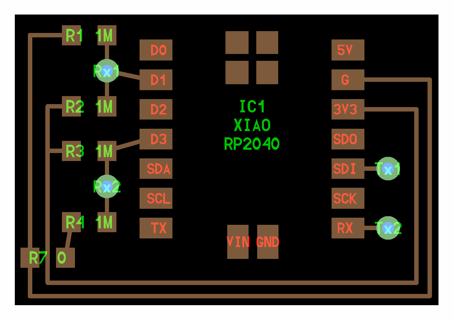
The first problem that I ran into was that the PCB board that I milled in week 5 was not meant to implement this sensor. Mostly, I used three out of four of my analog pins to light up LED lights, and I left the last one with no connection. Therefore, I had to break out a breadboard.
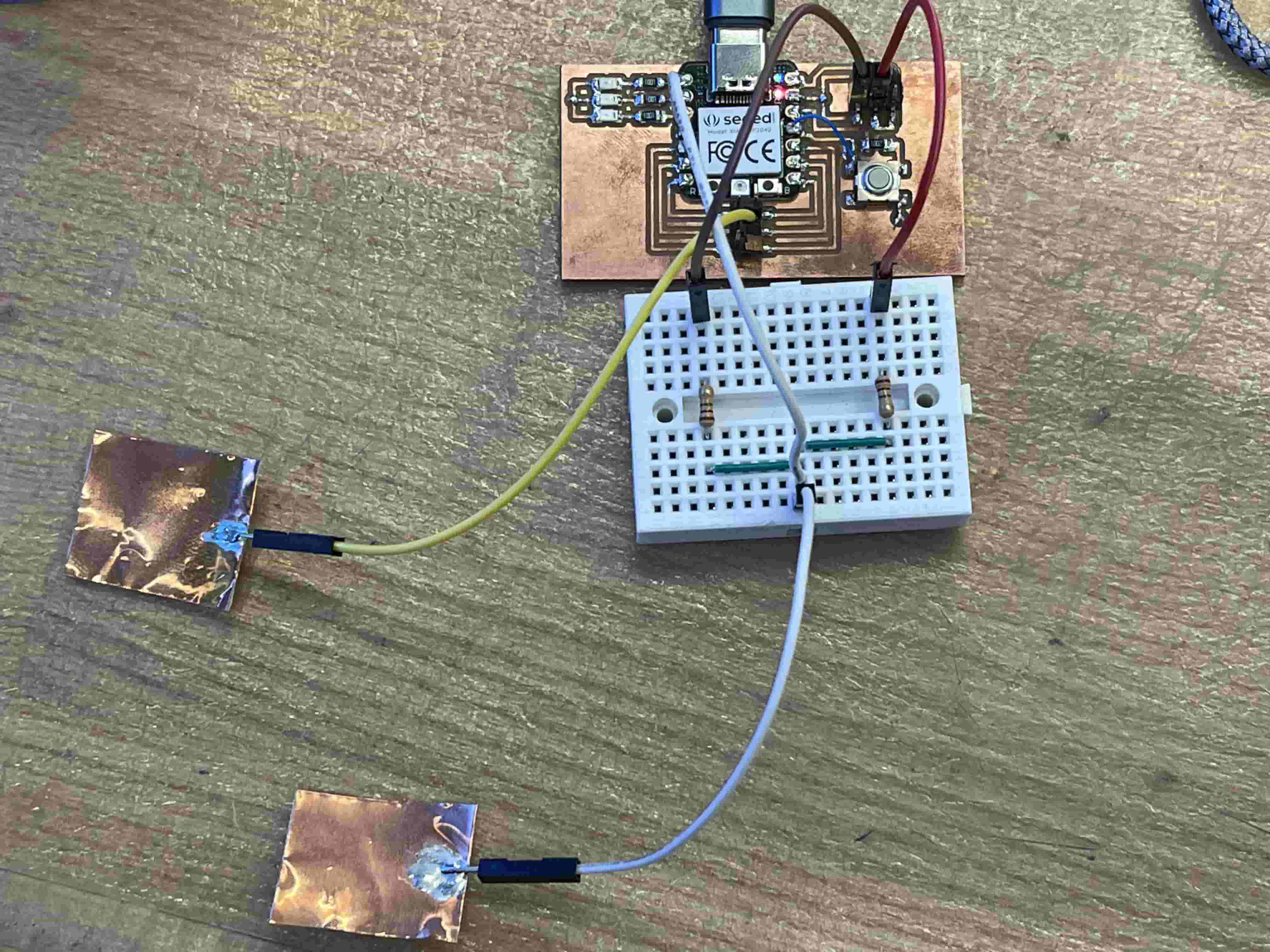
I closely observe Neil's example, and recreate it on my bread board. I solder the one last analog pin to a wire and use the existing connectors on my board for the transmitting pin, 3V3, and ground. I initially had a problem with my board no being recognized by my computer.
I debugged this issue by restarting Arduino, restarting my laptop, switching USB-C cable, and plugging a new XIAO RP 2040 in. My computer recognized the new XIAO board, so I unplugged my connections to the bread board and tried again; I observed that my computer do recognize the board when it is not connected to my beard board. That is when I realized I had connected ground to power.
After fixing it, my board works!
See below for the code that I used.
Modified of Neil Gershenfeld 7/10/23


#define digitalWriteFast(pin,val) (val ? sio_hw->gpio_set = (1 << pin) : sio_hw->gpio_clr = (1 << pin))
#define digitalReadFast(pin) ((1 << pin) & sio_hw->gpio_in)

#define Rx1 D3 // receive 1 pin
#define Tx1 D9 // transmit 1 pin (D9)
// #define Rx2 29 // receive 2 pin (D3)
// #define Tx2 1 // transmit 2 pin (D7)
#define settle 20 // settle time
#define samples 2000 // number of samples to accumulate

void setup() {
   Serial.begin(115200);
   }

void loop() {
   }

void setup1() {
   pinMode(Tx1,OUTPUT);
  //  pinMode(Tx2,OUTPUT);
   }

void loop1() {
   int32_t up1,down1; //,up2,down2;
   up1 = down1 = 0; //up2 = down2 = 0;
   for (int i = 0; i < samples; ++i) {
      digitalWriteFast(Tx1,HIGH); // charge up
      up1 += analogRead(Rx1); // read
      delayMicroseconds(settle); //settle
      digitalWriteFast(Tx1,LOW); // charge down
      down1 += analogRead(Rx1); // read
      delayMicroseconds(settle); // settle
      // digitalWriteFast(Tx2,HIGH); // charge up
      // up2 += analogRead(Rx2); // read
      // delayMicroseconds(settle); //settle
      // digitalWriteFast(Tx2,LOW); // charge down
      // down2 += analogRead(Rx2); // read
      // delayMicroseconds(settle); // settle
      }
   Serial.println(up1-down1); // send difference
   Serial.flush(); // finish communicating before measuring
   }