Presenting:
The BP Practice Bot
Are you an avid partygoer, but can't hit a cup when it comes to a good old-fasioned game of BP?
Get your shots in, it's time to get good.
Alright people, I’ve procrastinated on this long enough, it’s about time I started my writeup for my final project. At this point, I’ve already been working (at a snail’s pace, but still, working) for the last three weeks. So what’s the big idea? What is it I’m making? Well, a while back, I saw this great video by Mark Rober where he built a never-miss dartboard–he used computer vision to track the path of the dart, and the board itself would move to intercept it at the bullseye. My idea is something similar, but instead of darts, for the legendary college classic game of beer pong.
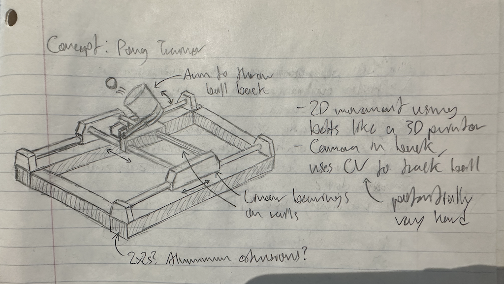 Imagine, a (red) solo cup that can move on a 2D-axis, guided by a pair of cameras that continuously triangulate the ping pong ball’s position mid-arc and use that information to determine where to move the cup to catch it. Now, on its own, the project is ultimately nothing but a useless novelty. It catches the ball. Cool, I guess. However, there’s a second part. Instead of just a static cup, put the cup on a little throwing arm. Then, you can also throw the ball back to the user, creating a gameplay loop. Now, you can use the device as a practice bot by constantly attempting to make shots. If your shot’s on target, the cup doesn’t move. If you miss, the bot catches the ball for you instead of the ball bouncing off somewhere and you having to run after it like a goofy. Either way, the bot then pops the ball back up at you, you catch it (hopefully), and can take another shot quickly. Essentially, you’ve created a closed-loop shooting gallery for beer pong. And that, I think, is pretty neat. I also genuinely think it’d be a useful tool if you wanted to get good at the game.
- cup (w/ throwing arm) on coreXY 2D axis
- two 640x480 usb cameras mounted at cup level at back corners, connected to a raspberry pi
- pi connected to motors via stepper controller, control + openCV all running in python
- motor positioning achieved by calibrating using limit switches, then just keeping track of rotations and not hitting edges
- thrown ping pong balls triangulated using dual camera setup. in case where user misses a shot, the cup moves to intercept and catch
 Now, that’s a nice idea and all, but back in reality there’s a bit of an elephant in the room. That’s an ambitious project. Building such a device from scratch entails involved mechanical, electrical, and software engineering. My TA described the idea as “a 2.12 final project, except instead of having four people and the whole semester, it’s just you.” I also started in mid October, so no whole semester either. So what’s the game plan? Well, given the rather lofty scope of this project, I’ve decided to segment my goals into three tiers, where only the first is absolutely necessary to complete as a final project goal. The others we can call stretch goals, and whatever I don’t finish by presentation day, I’ll add over IAP (after all, I’m really building the project for me, not just the class).
The first tier is just making the thing. This includes building the physical contraption, doing all the electronics, and writing whatever basic code is necessary to operate the motors and interface with the cameras. The second tier would be implementing the automatic catching. This part could be anywhere from straightforward to really difficult, so I can’t guarantee that I’ll be able to have it working by final project presentations. I do have a pretty promising (but untested) idea for how to go about doing this part though. The third tier encompasses the whole throwing the ball back part. That means the mechanical structure of the throwing apparatus, as well as potentially, code for calibrating the throw itself (for accuracy). But the bottom line is this: the final project is to build something; tier 1 satisfies that, so I feel that alone is enough to call a presentable final project. I’m not going to promise the rest, because auto-catching might end up being harder than expected.
Ok ok, enough theory, let’s get to the experimental stuff. Here’s how I actually made the thing:
 To make this project happen, I first needed a movable belt-driven 2D-axis gantry for planar motion. Think like, a 3D printer. In fact, much of this build was inspired by various elements of the Prusa MK3+. Like the Prusa, I would be using 1” aluminum extrusions for the frame. These would be connected together at the corners with 3D-printed L-sockets (henceforth referred to as “feet”). These feet would also support the gantry rails (8mm steel rods) and provide a place to attach some of the pulleys for the gantry’s coreXY setup. What is a “coreXY setup,” you ask? CoreXY is a method of arranging the belt system of a 2D-gantry so that you don’t need a moving servo mounted directly on the moving inner rails. Instead, both servos are fixed at the corners, and operate one of two symmetrically arranged belts. See the picture for a better idea. I’ll spare the details of the logic behind arranging things like this, but essentially if turning the servos in the same direction gives horizontal motion, and turning them in opposite directions gives vertical motion. It can be a little tricky to wrap your head around first, but what’s important is that not having a servo on the inner rails means the moving system is lighter, and can therefore be accelerated faster. This is of course, very necessary if we’re trying to catch a fast-moving ping pong ball.
So, after a quick thinking sesh (it wasn’t so quick, actually) to organize how I would arrange the rails and belts, I settled on a plan and got to CADing. I started on Fusion, but after 2 seconds of trying to use their sorry excuse for a mate feature to arrange components, I switched to Solidworks. Good ol’ Solidworks. It has its issues, but not like Fusion has its issues, especially when it comes to multi-component projects. Then again, maybe I just suck at Fusion, I don’t know. I began my CAD journey with the bottom left foot. I started by sketching out how the aluminum extrusions would fit together in the foot, and extruding up the L-socket.  I settled on 3/16” thick walls, and a socket tolerance of 0.1mm all around for the extrusion insert-holes. These values were determined by the infallible age-old process of guessing. At the top edge of vertical extrusion hole, I added a 0.5” deep circular socket (with 0.15mm tolerance”) for one of the 8mm linear rods that would make up the outer rails. Next came the servo holder. I opted to place the servos at the bottom (a.k.a front-facing) corners of the 2D-axis, since the cameras would need to sit at the top corners to get a view of both the player and the entire gantry movement area. I needed the structure to be stiff, so I wanted the servo holder to be supported from both the bottom and the side. The way I designed the supports to accomplish this meant that two of screw holes for the servo would be covered, but I figured two screws would be good enough. For the screw holes themselves, I just used Solidworks’ hole feature to make M3 holes. Finally, I added the holes for the screws that would secure the feet to the aluminum extrusions using 1/4”-20 screws (and T-nuts). These holes I made slightly bigger than 1/4”, and to avoid bridging issues at the top of the hole, I also added pointed tip at the top. It took a few print attempts to get the tolerances right, once everything was checked to fit nicely, I mirrored the bottom left foot to get the bottom right, and then moved on to the top feet.
 Here, I began with the top right. I actually started with a copy of the bottom left foot, which I simply deleted the servo holder from. This foot, instead, would support two pulleys for the belt system, as well as the camera stand attachment point at the back. The pulley structure was pretty simple, it was just an elevated platform with M3 screw holes located far apart enough that the two belts/pulleys wouldn’t touch. The platform was high enough that the pulleys would stand above the outer rails. The idea was that both the outer and inner rails would be located within the same “layer” of the build, and on top of that layer would be the belt “layer”, in which all the belts and pulleys would operate. This organization made the build a lot easier to design and manage. For the camera stand attachment point, I just added a small protrusion with two M3 screw holes that I could use to attach a camera arm, and that was that. The camera arm itself was just a pole with an angled plate attached to the end to screw a camera module onto. The plate was angled 20 degrees upward, and 35 degrees–or exactly half of the camera FOV–inwards. This is in an attempt to capture as much of play area as possible while still being able to see forward at the user and ball. Another mirror operation on the foot (and the camera pole) and the rectangular frame was ready.
 Now, all that was left was to design the part that moved. This was comprised of the outer trolleys which slid on the outer rails and held the inner rails, the inner trolley which slid along the inner rails, and the inner rails themselves. The trolleys needed to move on linear bearings, so I needed a way to insert a bearing into the part and have it fit snugly (you know, so it wouldn’t move). To accomplish this, I took a cue from the Prusa z-axis bearing holder design. Imagine, a 3mm thick circle arc of inner diameter equal to the bearing’s outer diameter, that only attaches one end of the circle to the rest of the trolley. Then, you extrude that circle into a cylinder (with a lengthwise cut in it) of length equal to the linear bearing. See the picture for a picture. This lets the holder bend a little bit so that you can insert the bearing, but still grips tight and keeps the bearing in place after. I decided that the inner rails would be spaced 2” apart center to center, just like the Prusa x-axis. This put the width of the outer rail trolley at 2.5.” Based on this, I added two bearing holders for two bearings, each at one of the ends of the trolley. I then cutout socket holes for the inner rails, of the same dimensions as those for the outer rails, as well as M3 screw holes on top for the two pulleys that would redirect the belts horizontally towards the inner trolley.
 Finally came the inner trolley itself, where the four ends of the belts were attached. In addition to strong connection points for those belts, it also needed four M3 screw holes in the top, to make it so I could add attachments (such as a solo cup holder) later. For the belt attachments, I took another page out of Prusa’s book and used a similar method to the MK3+ extruder belt attachment. These were simply complementary belt-shaped cutouts that you could slide the belts into. I modeled these in using the dimensions of the GT2 belts I had bought as a guide, essentially just extruding a complementary tooth profile into the top of the trolley to grip the belt well (four of those, more accurately). I also made the cutout 0.1mm wider than the 2mm thickness of the belt, to make it easier to get the belt in there. The linear bearing attachments were the same as for the outer trolley, except I only used one per rail instead of two. I did this because wanted to make the inner trolley width in the direction of the rails as small as possible so that it would have more room to travel horizontally. I also went back and added attachment points for end stops on the back left foot and left outer trolley. It was a quick matter of adding some minor geometry changes–a protrusion on the front of the foot and an inset region on the trolley–and some #2 screw holes, all based on the schematic of the end stop linked here.
 This concluded the designing phase, and it was time to get printing. Before this however, was a quick interlude to cut the steel rods for the rails. Funny story about that, I first bought rods on Amazon, but when I went to the shop to cut them, nothing (except a Dremel hard-edge grinder) would make a dent. As it turned out, I had bought case-hardened steel rods, which were impossible to cut without a lot of unnecessary time and effort. So my shop head and I ordered some regular old 8mm steel rods on McMaster Carr, and those were easy enough to cut on the bandsaw. Interlude over, back to 3D printing.
Most parts took two or three tries to get right, mostly fit/tolerance tuning and print failures. I also broke a few feet, several were too tight on the extrusions and got broken trying to get them off. And I destroyed an M3 hole on one rear foot by drilling a screw in and out too many times while trying to straighten it.  A note on using screws with 3D printed parts: my strategy for screw holes was literally just to create an M3 hole (which is slightly smaller than the screw) and then use a drill to drive the screw into the hole. This process sort of “threads” the hole, but really it just melts the plastic around it. It creates a good fasten at first, but it doesn’t last many cycles if you repeatedly screw and unscrew something into it, because each time you’re actually damaging the hole walls. Additionally, when you’re first “threading” the hole with a screw, you have to make sure you keep it as straight as possible, because otherwise you will be stuck with a crooked hole. I’m not exactly sure why, I would’ve figured that the hole wall would act as a pretty good guide for the screw, but I guess it’s easy to burrow into the side with a metal screw and a drill. Just be advised if you decide to use this method in your own projects. Support material was key for a lot of these prints. I found Prusa’s organic supports to be useful for the insides of the feet, especially with regard to ease of removal. For the outer trolleys, I first tried printing upside down, but quickly found that a side orientation produces a much higher quality part, especially for the bearing holders. The inner trolley was printed upside down, since the belt mesh teeth were small elements and needed to be printed flat.
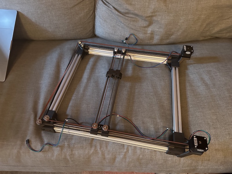
Once I got the parts printed nicely, assembly was pretty quick. Screw extrusions into the feet (specifically, into t-nuts inserted into the extrusions). Screw end stops onto the back left foot and left outer trolley. Screw pulleys onto outer trolleys and rear feet. Assemble inner rail system with inner and outer trolleys. Place on outer rails and assemble with frame pieces. Screw servos (with driver gear attached) to front feet. Belt everything up. And boom, we have a milestone. I’m switching to the present tense now because we’ve reached the present (at the time of me writing this, anyway). Now I have the physical movement mechanism done, and I can move on to electronics. My immediate next steps are to wire up the steppers to these STSPIN820 stepper drivers I bought, which will then connect to Raspberry Pi running control code. I’ll also need to wire up the end stops to the for positional calibration, as well as attach the cameras. Hopefully by next week I can get that circuitry up and running to the point where I have full positional control of the gantry. We’ll see.