Weeks 5 and 6:
PCB Design + Production Weeks. Homework was to design and fabricate a custom printed circuit board.
Weeks 5 and 6 were really just a singular, extended, assignment, so I’ve decided to document both weeks in a single writeup.
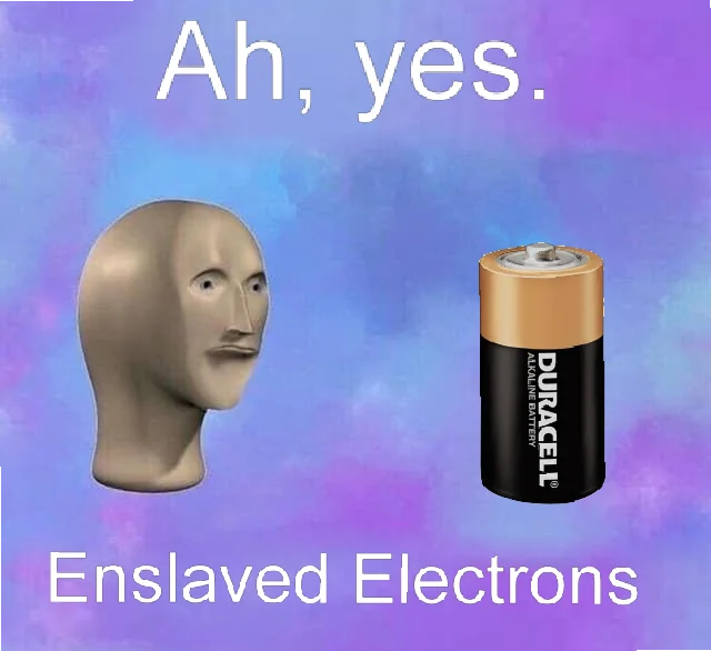 I spent a while going through ideas on what to do for my PCB. Some options I considered were doing something for my final project, or making an interesting design on the board. But, there were other things I had to do for my final project before it made sense to do any electrical work for it. And honestly, I was more concerned with learning the skills involved in the PCB-making process than actually building anything of particular use. So, I just decided to have some fun with the assignment. There was this surreal meme from a few years back that I found pretty amusing. My freshman year, me and my roommates actually had a massive printout of it on our wall for a while: I figured, I could put my circuit where the battery is in the image, and then make myself a PCB version of the meme. And since you have a functional computer there, I guess you really do get the enslaved electrons too. Silly concept, I know. But hey, I’m a silly individual.
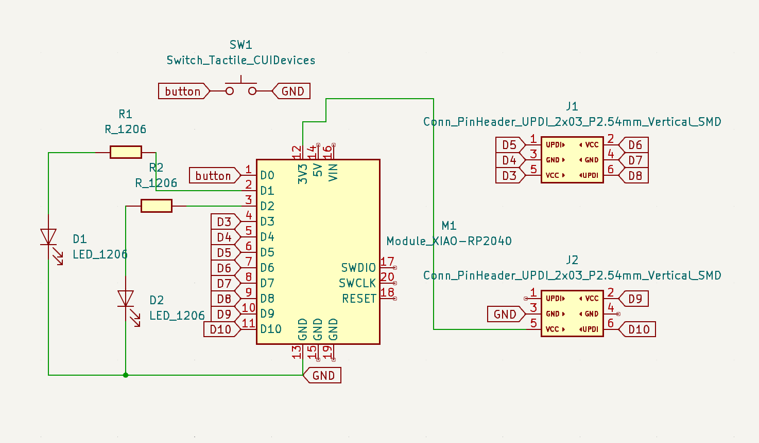
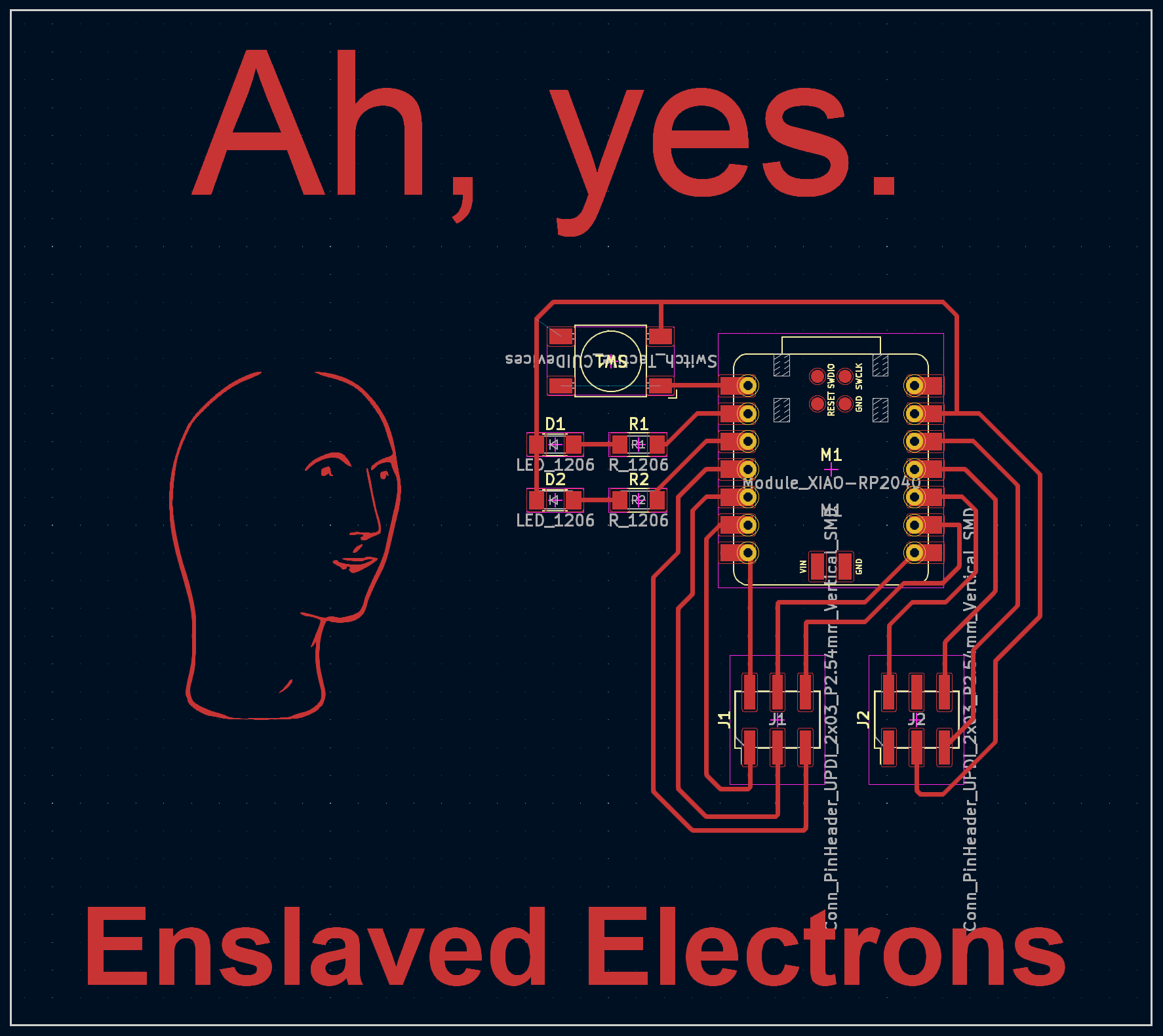
I chose to use KiCad for my design work, as I liked its user interface a bit more than Eagle’s. I kept my circuit design pretty simple, just a XIAO RP2040 connected to a button and some LEDs, as well as some headers to break out the 2040’s pins. Once I had my schematic for my component connections set up, I moved into KiCad’s PCB design application. There, I drew all of the traces that would connect my components, and also added the meme text above and below my circuit. For the face image to the left of the circuit, I took an image of the face and ran it through an png to svg converter, then imported the svg into KiCad.
 That pretty much concluded the week 5 festivities. For week 6, with the designing out of the way, it was time to get down to making the actual board. After a quick tutorial on the OtherMill from my TA Anthony (shoutout), I proceeded to make my first copper cutout. Unfortunately, this one didn’t turn out very well. The cut edges were all fuzzy, and more importantly, my traces were far too thin! Some of the worst offenders had even started peeling off the board backing, making those connections unusable (see the top right of the circuit). As it turns out, simply running with the default design rules and hoping for the best was not an efficient strategy for producing a quality PCB, especially when your traces are set to 2mm thick instead of the recommended 4mm. Whoops.
After some quick updates to beef up my traces, it was time to have a second go at it. I uploaded my new design to the OtherMill, configured the correct settings, and sent it. All good, right? Nope! About 2 minutes into the process, the 1/32” toolhead broke off while routing a line! After some consultation with Anthony (shoutout x2), it turns out this wasn’t really my fault, either someone had dropped the bit prior to me using it, or it was just dull from repeated use. Either way, he got me a new bit, and all I needed to do was re-run the cut. I didn’t even need to get a new copper plate, it was as easy as just redoing the path with the new bit. And this time, it turned out great. I guess a brand new cutting head will do that for you.

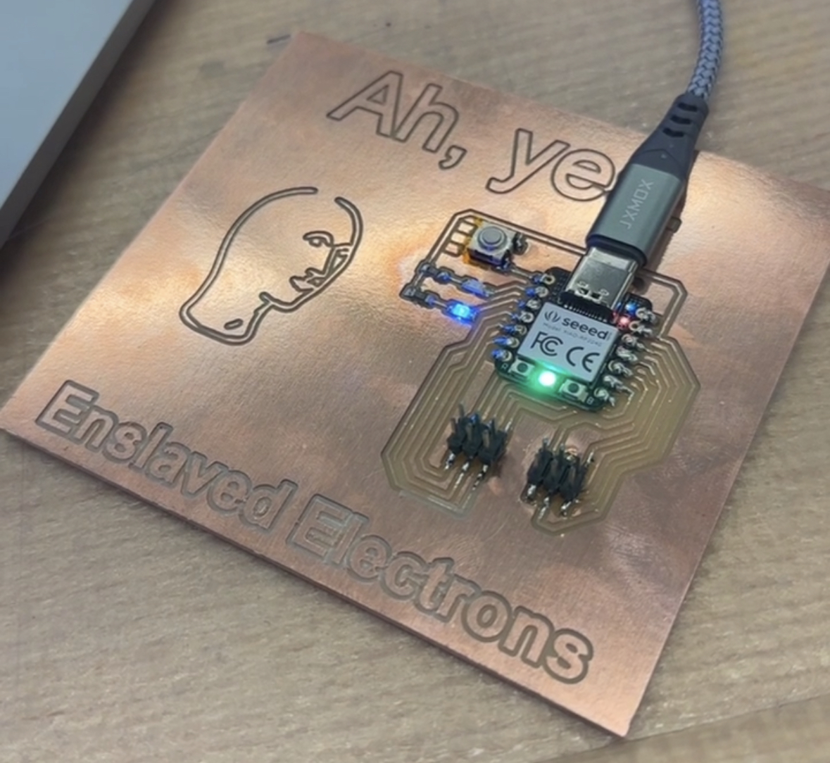
Now I had my board, and all that was left was to solder the components to it. I had actually only ever soldered once before, so I was a little intimidated at first, but Anthony (shoutout x3) gave me a nice tutorial on soldering both with an iron and with hot air. Gotta hand it to him, the guy has been coming in clutch week after week. It took me about 45 minutes to get all the components done, with the only hiccup being that the traces for my button were a bit too far apart. I addressed this by taping over the two connections that would have contacted the main copper body and shorted, and only soldering the other two that were correctly positioned above the correct spot on the board. You can see the traces that were two far at the top left of the circuit, left of the button. While it’s certainly far from high quality soldering work, everything ended up functional, so ¯\_(ツ)_/¯.
I tested all the components with a small amount of code, just a little something that flips which of the two leds is on when you click the button. Is this the world’s first instance of writing code on a meme? Maybe. Probably not. Nevertheless, it’s a pretty amusing end product in my opinion, and that’s certainly enough for me.