Week 8:
Woodworking week! Homework was to make something on the CNC mill out of OBS.
A trebuchet was the first idea I had when Prof. Gershenfeld went over this week’s project. I reconsidered for a moment after he added the “”suggestion”” that our project also be held together without metal fasteners or glue. However, I quickly concluded that I could still get it done, even if it may potentially be a little annoying.
 The first step was, of course, a good CAD. I began with the main vertical supports, opting to go for two large triangular cutouts with thick beams for strength. These set the height of the trebuchet, which I decided would work best at 20 inches tall for a good balance between size and material usage. I also added six cutout slots, two in the middle and four on the sides, for lateral interlocks that would connect the two vertical supports together to create the trebuchet frame. Note that these cutouts had to be placed low enough on the trebuchet to avoid the counterweight slamming into the lateral beams on descent.
 Naturally, next I added the actual lateral interlocking beams. I ended up only placing four of them, opting to not include the middle ones since they seemed a bit unnecessary (though I never did remove their corresponding cutouts on the main supports). I also tapered the slots on the lateral beams so that pushing them farther into the main supports would create a tighter fit, and thereby a stronger frame for the trebuchet. Not a whole, lot, just 1 degree, but enough to create an extremely tight grip when hammered in.
 After the frame was completed, I tossed in the main axle, then began to CAD the arm components. I opted to go for a three-piece design where two secondary arms supported to the counterweight from the very outside, thereby preventing lateral motion along the axle, while the primary arm sat in the middle of the axle and extended back as the the launch arm. What I should have done was also add some sort of spacers in the extra space between the primary arm and secondary arms, since my current design allows the primary arm to slide along the axle. So why didn’t I do this very obvious thing? Well, I was so focused on making sure they counterweight couldn’t move laterally and collide with the sides of the main supports, that I just didn’t notice the primary arm issue. Whoops.
 Anyway, with the arms finished, all that was left to whip up a counterweight–a box-looking one like in all the pictures of medieval trebuchets I found online. I tossed in the counterweight axle, then sketched around it the side walls from which the counterweight would hang. At each of the side edges, I added a long interlock meant to slide an end wall into, and near the bottom, holes to hold the floor. Consequently, the floor was designed with small outcroppings to fit into these holes, and the end walls with complementary long interlocks to mesh with the side walls. I also filleted all the openings of the various slots/cutouts/interlocks, as well as the edges of the counterweight floor outcroppings, so that parts could be slotted together more easily.
 That was all for the CAD, so it was time to move on to manufacturing. The CAM setup was pretty simple, I just used the arrange feature in the manufacture tab of Fusion to lay all my components (minus the axles) flat, followed by a 2D Contour run to generate a machining path. Machining took about 16 minutes, which wasn’t bad. An additional 25 was spent cutting away all the little tabs holding my parts in place with an oscillating saw, which was a bit more tedious (though kind of satisfying, too). Then, another 10 to clean up some remaining imperfections with the bandsaw. I also had to make two cuts on the metal rod I intended to use as my axles.
 But then, finally, it was assembly time. This took about 10 minutes, and honestly went far better than I expected. Unfortunately, I didn’t take any pictures because I’m silly, so you’ll just have to visualize all this from writing. First, used a small 2x4 to hammer in the lateral beams into the main supports. This provided me with a sturdy frame. Then I hammered the main axle through one of the supports (because the hole fit was exact, and therefore very tight), and about 80% of the way through the middle space between supports. I then slid on one secondary and the primary arm, which could rotate freely on the axle due to the added 1/16” tolerance on their axle holes, and then hammered in the counterweight axle so that it was flush with the outer surface of the one secondary arm.
Next, I assembled the counterweight–inserting the floor into the side walls, then sliding in the end walls–and slid it onto the counterweight axle. Again, free rotation due to the same added hole tolerance. Finally, with some brute force and hammering, I added the other secondary arm on both axles, and pushed the main axle all the way through to the other side. And boom, done, and the trebuchet even moved well on the first try. I was a bit concerned that my tolerances wouldn’t work out, because they can be finicky like that, especially, when working with an imprecise material like OBS. But everything fit together quite well, and with adequate strength. Apart from one post-assembly edit, where I had to saw off the edges of the counterweight end walls for more clearance between them and inside edge of the main supports, I didn’t even have to iterate on anything. Well, with the exception of the trebuchet sling, which started off as a covid mask that didn't work that well, and after a few attempts became a taped-up piece of fabric.
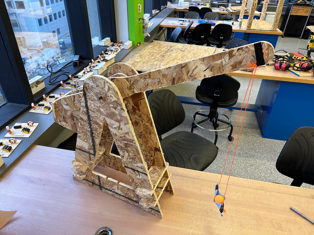
There is still an issue with the primary arm being able to move side to side, which leads to occasional collisions between the counterweight and main supports. And the launching itself doesn't go very far. But I mean, hey, I said I was going to make a trebuchet, not necessarily a good one. So there you have it.
Voilà, un trébuchet