
HTMAA Week 8
Assignment Description:
make (design+mill+assemble) something big (~meter-scale)
Finished Product
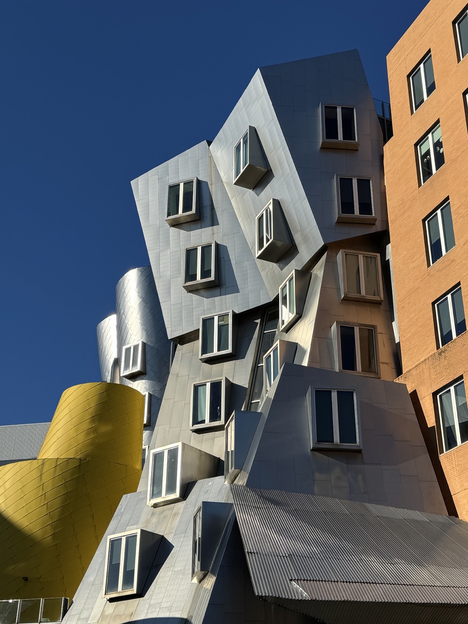
This week I made a (big) pinhole camera!
Focal length: 330mm
35mm Equivalents: 30mm (16"x10"), 44mm (8"x10")
Max sensor size: 16"x10"
Aperture: f431
Max Angle of View: 75°
This was my first ever woodworking project, and it turns out making even just a box is a lot of work! Luckily I was even able to take a couple of photos with it and develop them. I had a ton of fun this week, and if you're interested in following the journey (or potentially making one yourself), read on!
Materials
- ~65% of a 4'x8' 3/4" Pine Plywood Sheet (could squeeze to a 4x4 with some creativity likely)
- Soda Can
- Black spray paint
- Ilford Photographic Paper
- Ilford Multigrade Developer (DIY alternative: Caffenol)
- Ilford Rapid Fixer (DIY alternative: salt water)
Tools
- Shopbot CNC
- Laser Cutter
- Safety pin
- Sandpaper
- Light Meter (MyLightMeter)
- Pinhole design calculator
Inspiration
- Brendan Barry: The Camera Maker
- DIY Darkroom Chemicals
- Shed camera
- Contact Prints with Paper Negatives
Camera Design
A pinhole camera is essentially a light-proof box with a tiny hole rather than a lens. They vary widely in shape and size, from taped-up shoe boxes with paper negatives to purpose-bilt pinhole lenses mounted to DSLRs. Because of their tiny apertures, pinhole cameras typically come with the caveat of long exposure times, ranging anywhere from a few seconds to years.

Most pinhole cameras take on a pretty modest size, using objects such as soda cans, oatmeal tins, and shoe boxes to expose on to paper or film negatives 4x6 or smaller. However, since this week's assignment was to make something "big", I made a big one.

The design isn't anything crazy, it is a box with a hole and a place to put film. However, the dimensions of said box matter depending on what properties you want out of your camera (angle of view, exposure time, "sensor" size, etc.). While you can theoretically start from any of these points to drive the rest of your design, I based mine upon the "sensor" size (note the use of air quotes to indicate we are not using a sensor in the digital sense, but photographic paper of pre-cut sizes). Given the theme of the week, I wanted to go as big as feasibly possible. I acquired the paper from Hunt's Photo and Video in Harvard Square, and the largest format they had was 8x10. I didn't feel like an 8x10 camera was *quite* big enough, so I set my max sensor size at 16x10 (two 8x10's next to one another).
In order to help me along in tweaking the camera parameters I utilized this fantastic guide and associated spreadsheet. A 30mm focal length equivalent seemed like a good target for having a wide angle of view when using the full sensor, still giving room for 8x10 and smaller use (44mm equivalent). If you have the flexibility to design every parameter, I'd recommend starting with the sensor size, then a focal length you like. Regardless, understanding the full frame focal length equivalent of your camera is incredibly useful for framing your shots.
Not all pinholes are created equal. The "optimal" pinhole size for a given focal length and sensor size can be determined with Rayleigh's equation, d=2√(fλ/(m+1)), where d is the pinhole diameter, f is the focal length (or distance to the image plane), λ is the wavelength of light (for black and white photo paper, we use the wavelength of blue light, 480nm), and m is the magnification (if you're taking photos of objects past 2m, 0 is fine). My optimal pinhole calculated out to be approximately 0.8mm.
Making the Pinhole

For best imaging performance, you want your pinhole material to be as thin as possible while still being rigid. It is possible to use something like aluminum foil, but it will be more fragile. I opted for a RedBull can. If using a soda can, make sure to tape over your edges, they can be sharp!
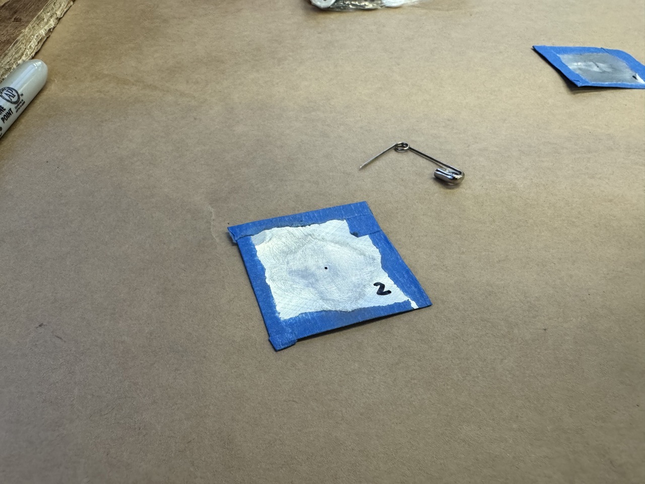
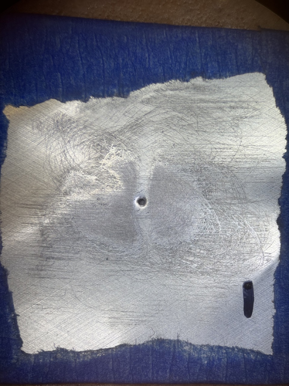
I made two different pinholes, one with a sewing needle (shaft diameter 0.59mm), and the other with a safety pin (shaft diameter 0.75mm). I gently pushed the pin onto the aluminum and spun it in a circle. Once a dimple appeared on the other side, I sanded it down until a tiny hole appeared. I repeated this process, slightly expanding the hole then sanding. I was more patient on the second one, as you can probably tell by the cleaner hole:

I took the pinholes under the microscope to try to measure their diameter. Anthony provided me with this awesome slide with 0.01mm markings! This microscope wasn't powerful enough to see them, but they are there.
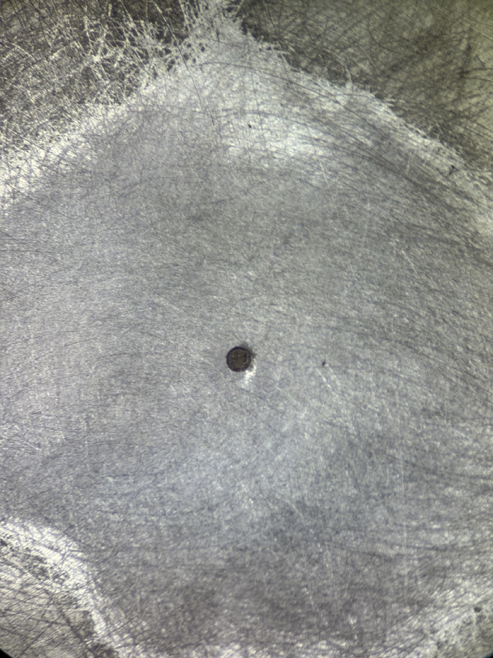

After fiddling with it for a few minutes I had a wicked headache, so I called it good that it is somewhere between 0.75mm and 0.8mm.
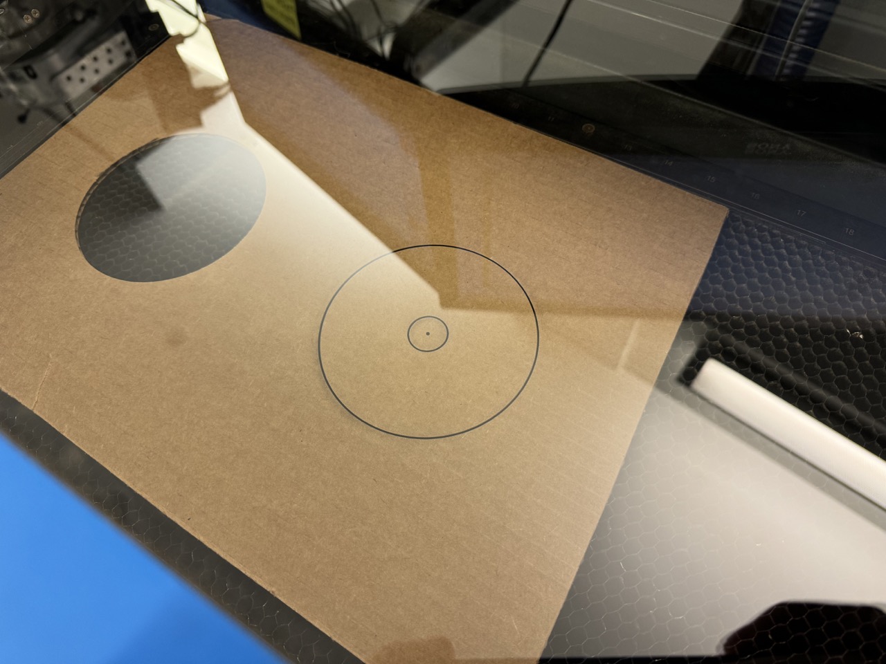
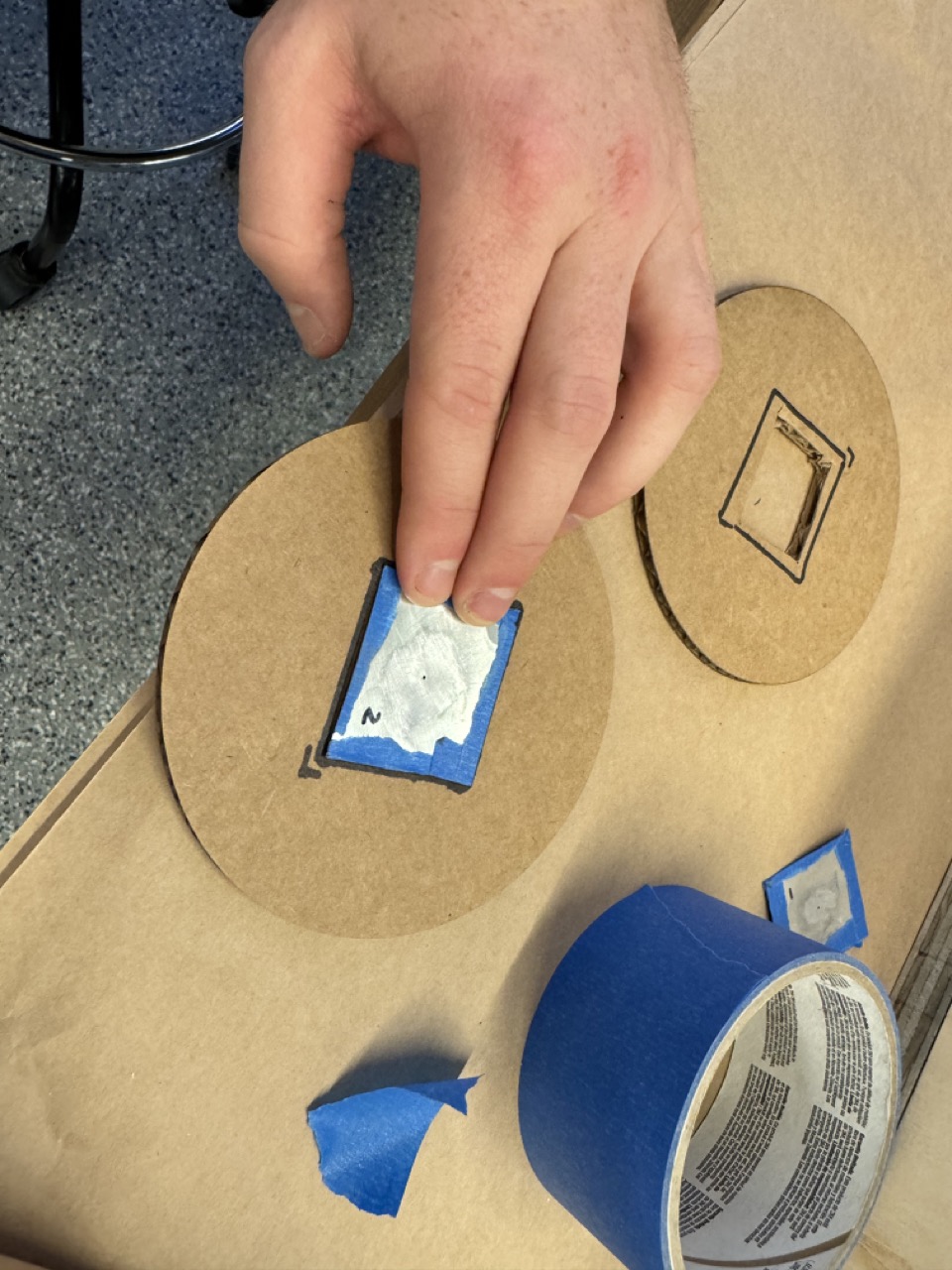
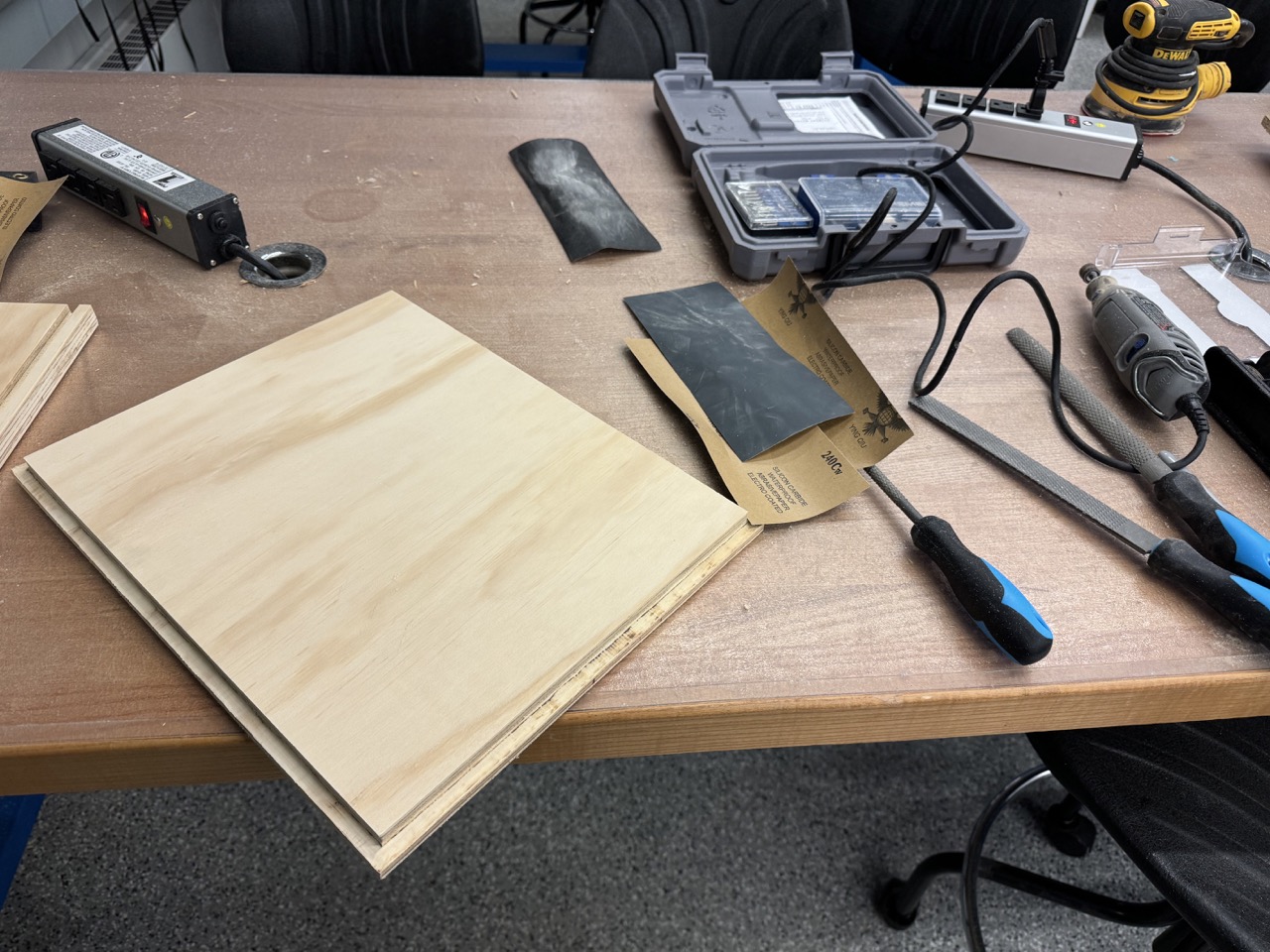
In order to mount the pinhole, I lasercut a cardboard disk. I utilized two different power levels in order to cut the disk and center mark, but only scored the internal disk that would be removed. This allowed me to ensure I was mounting my pinhole in the center.
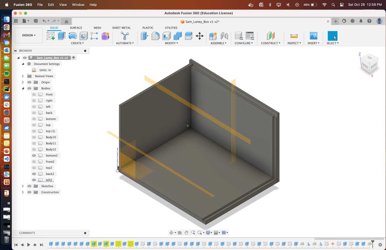
Designing in CAD
Once I had my camera parameters, I designed the box itself in Fusion 360. Shoutout to Adam for helping me with the design and offering his woodworking expertise. I decided that I wanted to keep this project, so I opted for plywood rather than OSB. The sturdier material provided more flexibility in designing the joints. I worried that the traditional approach of tabs and dogbones would be a light leak disaster (remember, the box has to be 100% light-tight outside of the pinhole), so I opted for this combination of notches and datos.
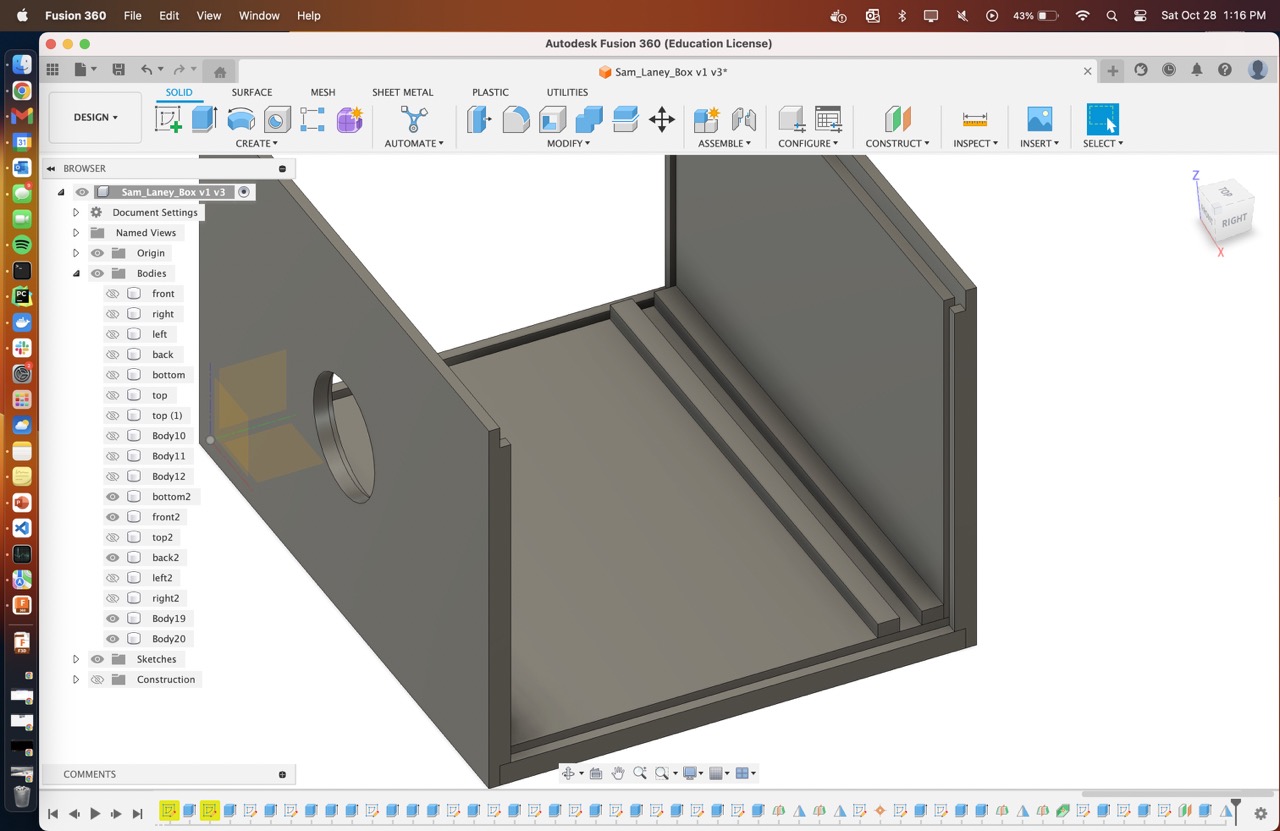
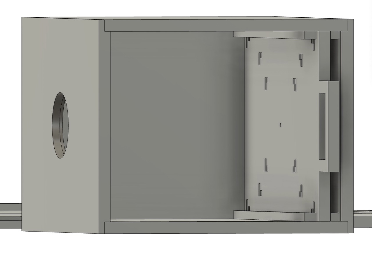
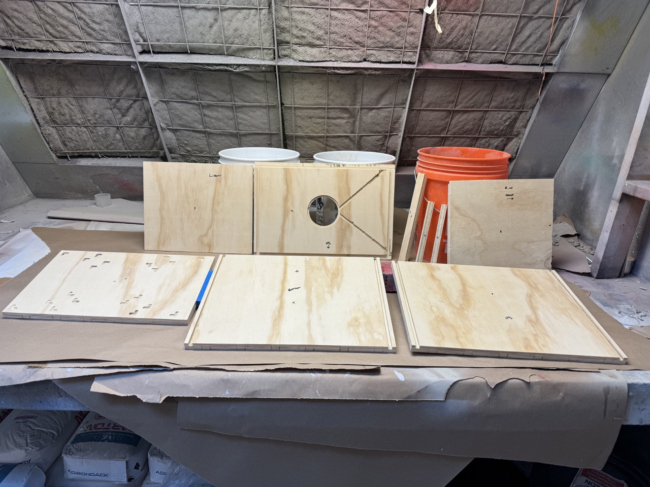
I designed this removable panel for the image plane. I included guide rails to ensure the plane remains straight and at our intended focal length. The recessed alignment corners allow me to properly line up the paper when I mount it in the dark.
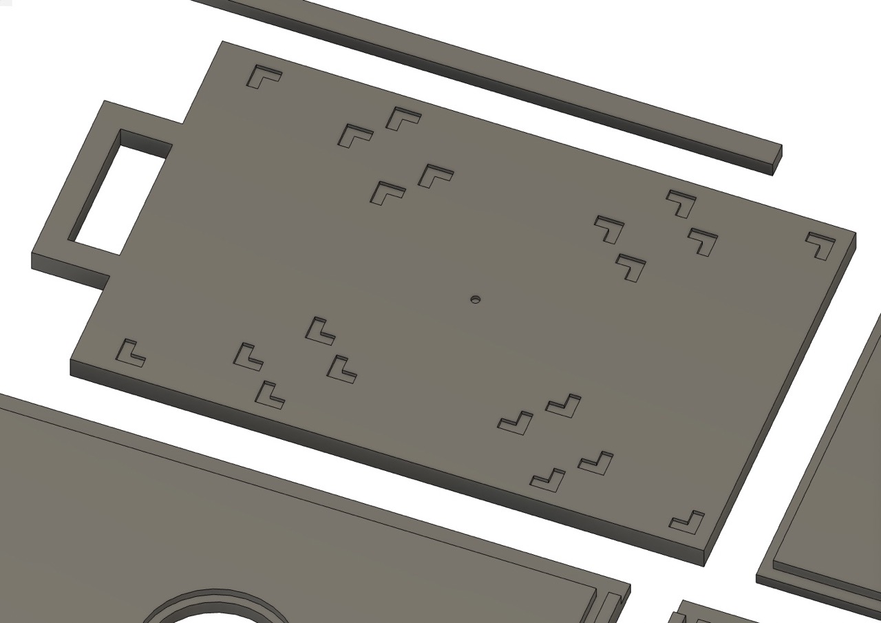

Arranged out, this took up just over one 4x4 sheet.
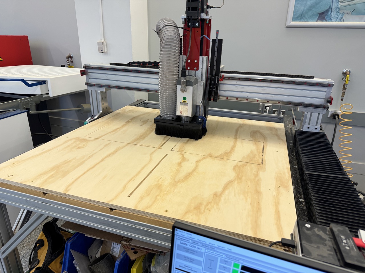
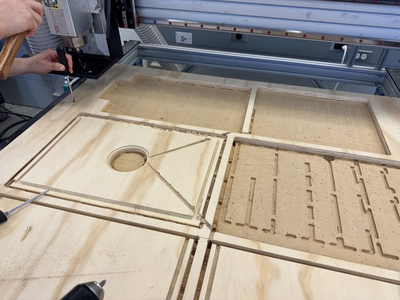
Machining
For CAM I utilized a combination of 2D contours and 2D/3D Adaptive clearing, using the 1/4" flat endmill for the smaller features and the 3/8" flat endmill for the border cutouts. Lesson learned, use 3D adaptive clearing. 2D does not have a notion of stock height, which led to a near critical failure as seen on the right. While the it milled out some material, it made rapids into the waste material, causing the Z alignment to be thrown off. This led to the diagonal cuts on the front panel and the mill blowing through the tabs and into the MDF. Thankfully we noticed it and stopped the job before anything bad happened. Also, use rest machining! Anthony and I wasted a lot of time watching the mill slowly cut air through the datos that had already been milled. Also, I forgot to select the contour to cut the handle out. Oh well.
Assembly
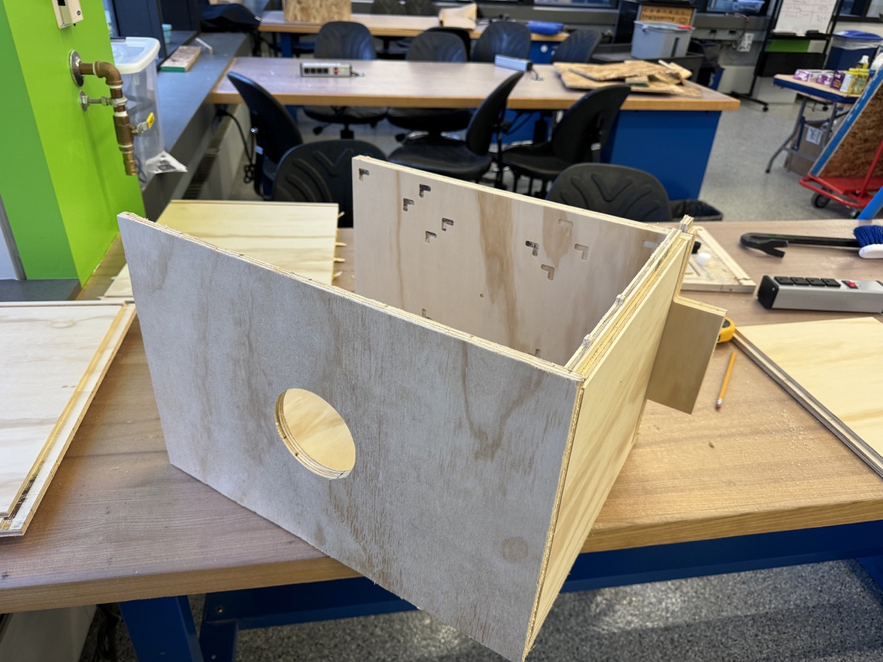
After machining, I tested the fit of the parts. the wood varied in thickness slightly, so I had to do some sanding to coax some of the joints into cooperating. I recommend a combination of rasps and a dremel with a sanding drum. In hindsight, I probably should have included a bit more room inside of the datos for clearance.
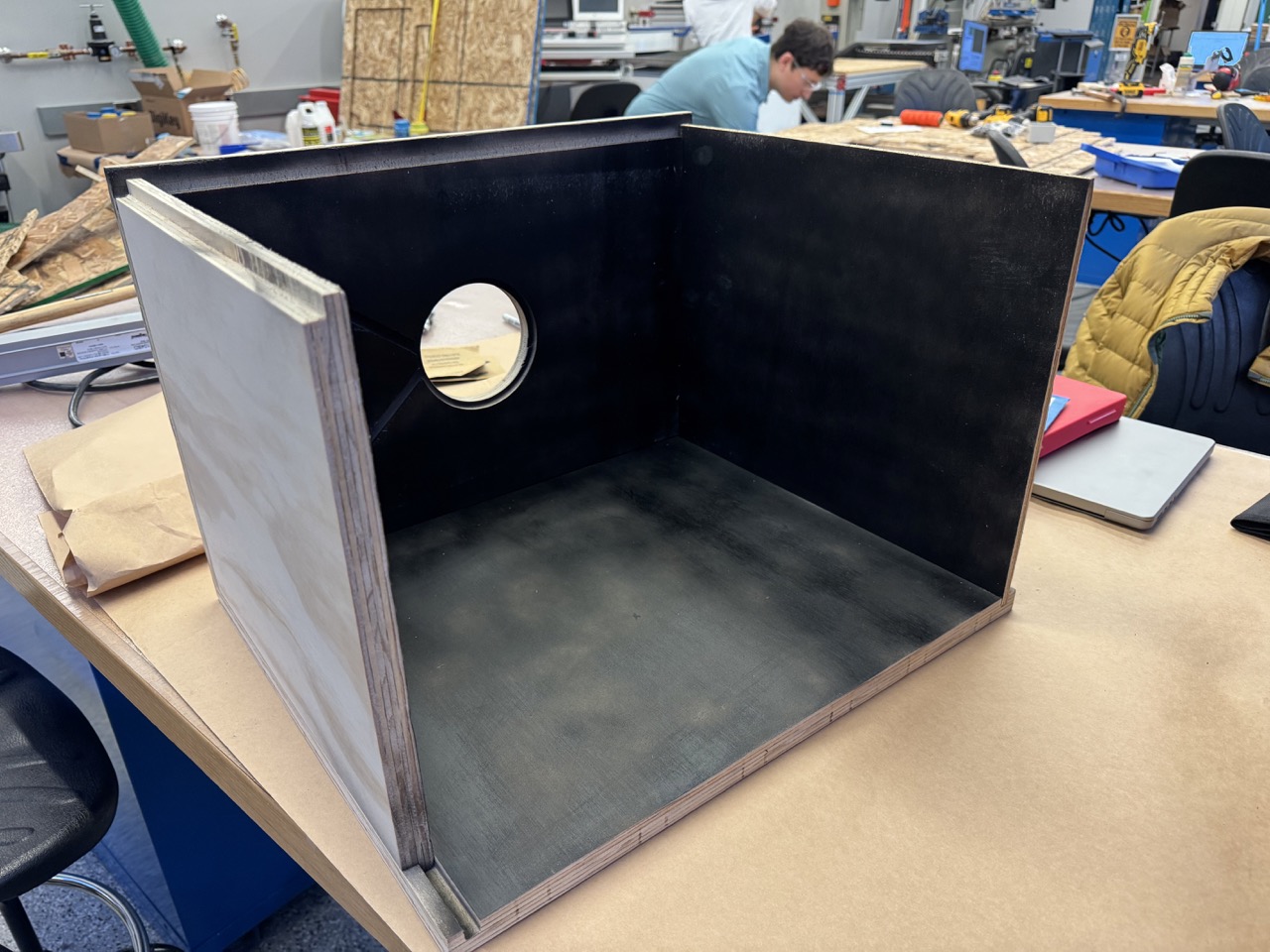
In order to limit light reflections within the camera body, I spray painted the interior black. Shoutout to Jen in the Architecture shop for letting me use her spray booth! It's not the cleanest paint job, but since it's an interior finish, I didn't mind too mcuh. I also simply ran out of paint.

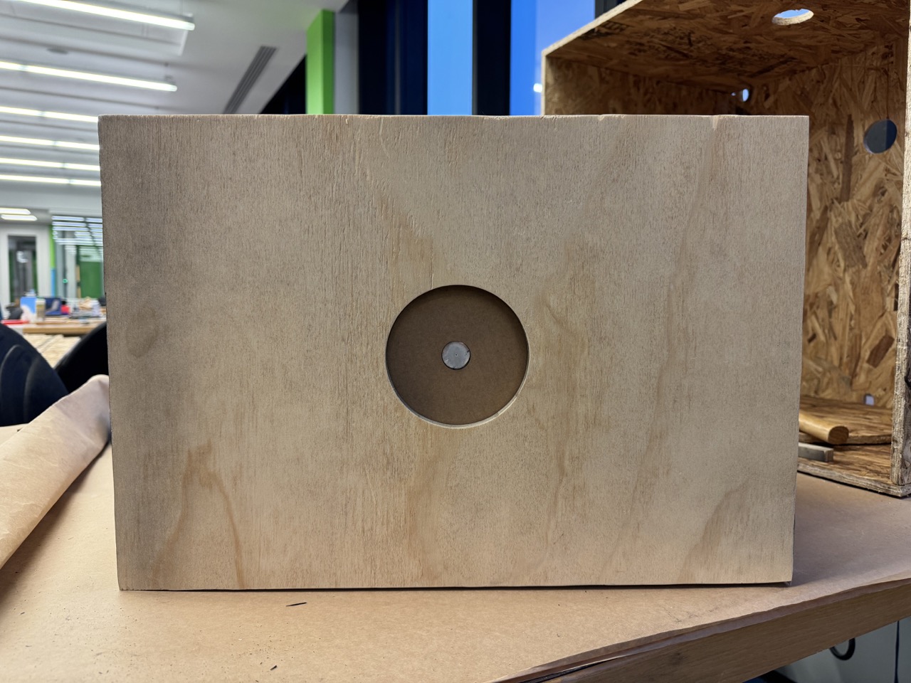
Finally, I assembled my (big) pinhole camera!
Loading the "Film"
As I mentioned, I am using Ilford darkroom photographic paper for my sensor. Traditionally, this is used for printing from film negatives, but it can be used as the "film" itself. Sheet film is far too expensive and is overkill for our humble pinhole.
The paper must be loaded into the camera in darkness/under a safelight. Shoutout to EDS for letting me use their supply closet:
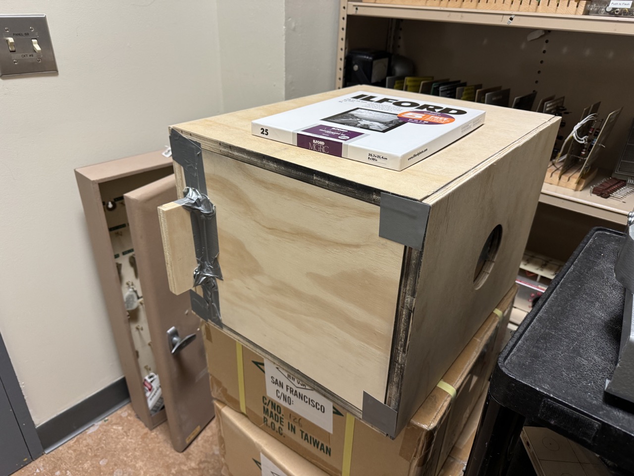
There is clearance between the film panel and the adjacent wall so the paper doesn't get scraped, but this also means there is an open lane for light to leak in. Nothing some duct tape can't fix!
Taking a Photo
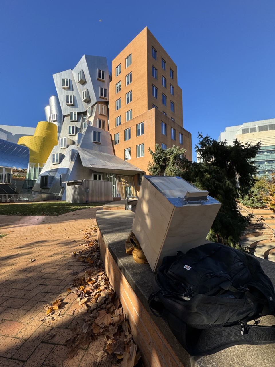
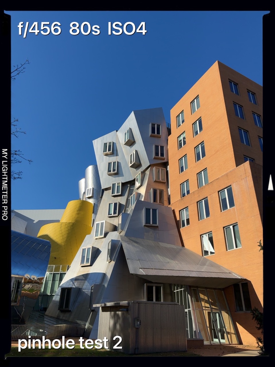
As I mentioned earlier, understanding the 35mm full-frame equivalent focal length for your camera allows you to actually (roughly) frame your shots! I used my iPhone to do this. Apple states that the 1x base zoom of the main lens is a 24mm equivalent, and that 1.5x is 35mm equivalent. Therefore, my "30mm lens" (16x10) is roughly a 1.3x zoom on my iPhone. My "44mm lens" (for 8x10) is a 1.9x zoom.
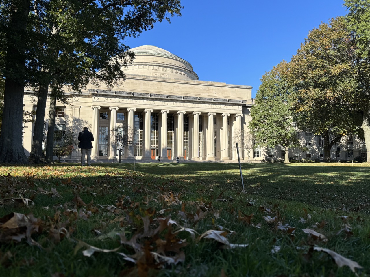
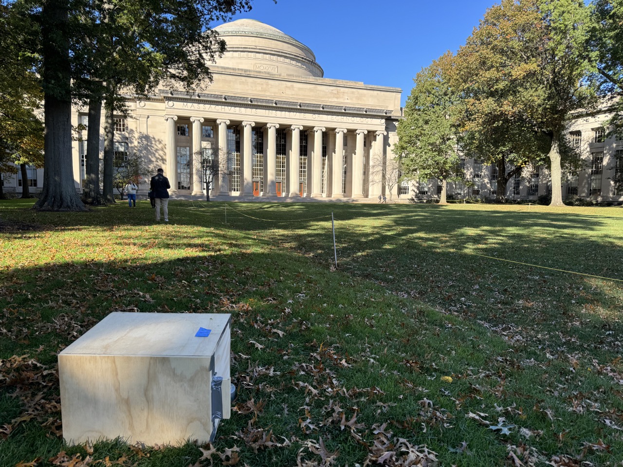
By placing my phone camera at about the pinhole, I got this reference photo and took an exposure of 3.5 minutes. I used the myLightMeter app to measure the exposure at ISO 4. I roughly doubled the app's recommendation to account for reciprocity failure, but I think this was too much as the negative came out overexposed.
I repeated the same process (unloading and loading in between) at Stata, but with a single sheet of 8x10, effectively "zooming" the camera with the smaller sensor. This exposure was 2 minutes and came out nicer, but still overexposed. I need to just trust the light meter.

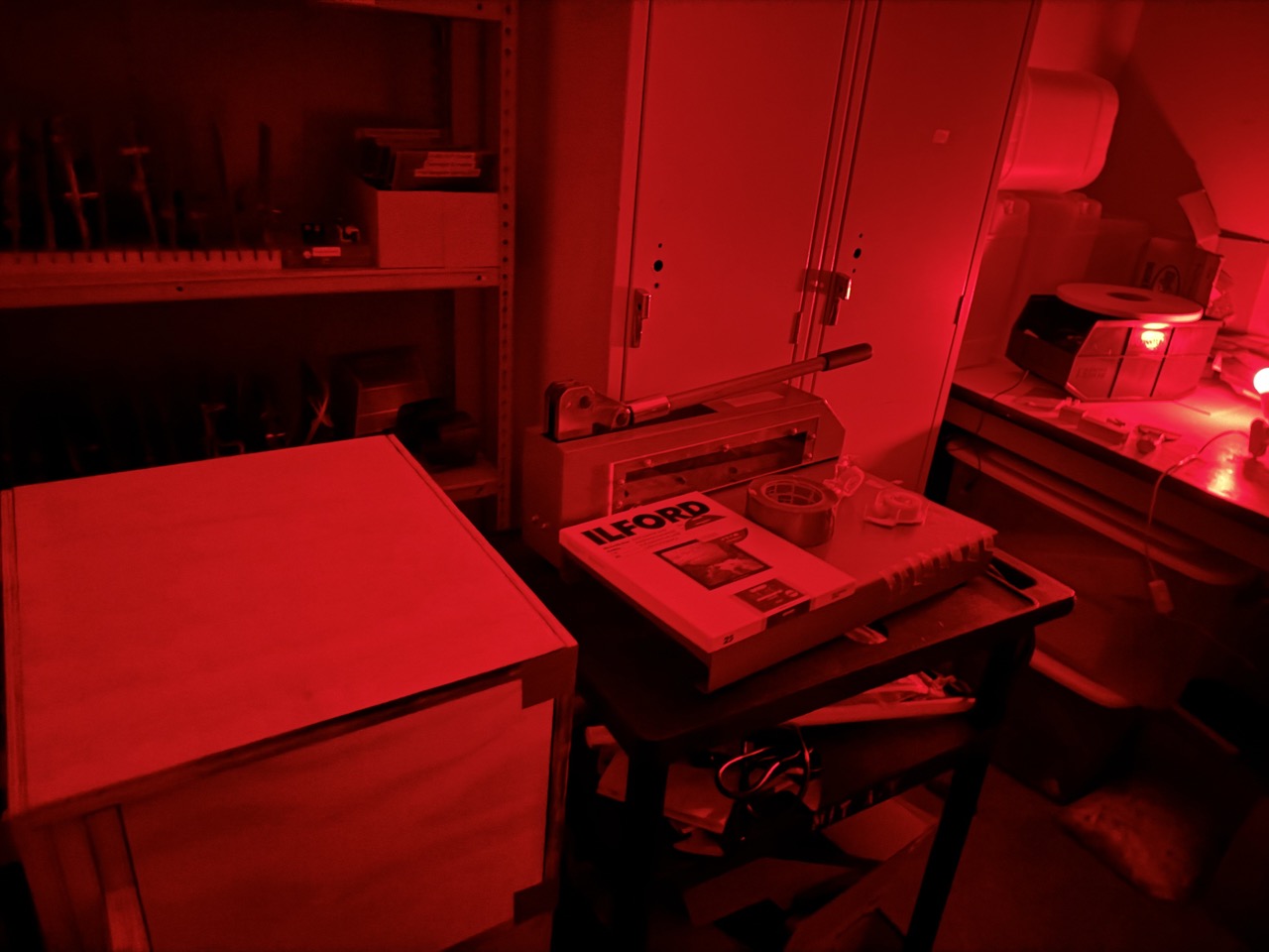
Developing

I could not find a darkroom available to me on campus, so I made my own! Hunt's carried everything I needed.
A Note on Safety
Darkroom chemicals are pretty nasty. While B&W chemicals are tamer than color ones, they still should be respected and handled accordingly. Make sure to always wear gloves and work in a ventilated space. One can also explore DIY alternatives such as Caffenol. When done with chemicals, make sure to dispose of them properly.
I had three baths: developer, stop (water), and fixer. Finally, rinse with water.
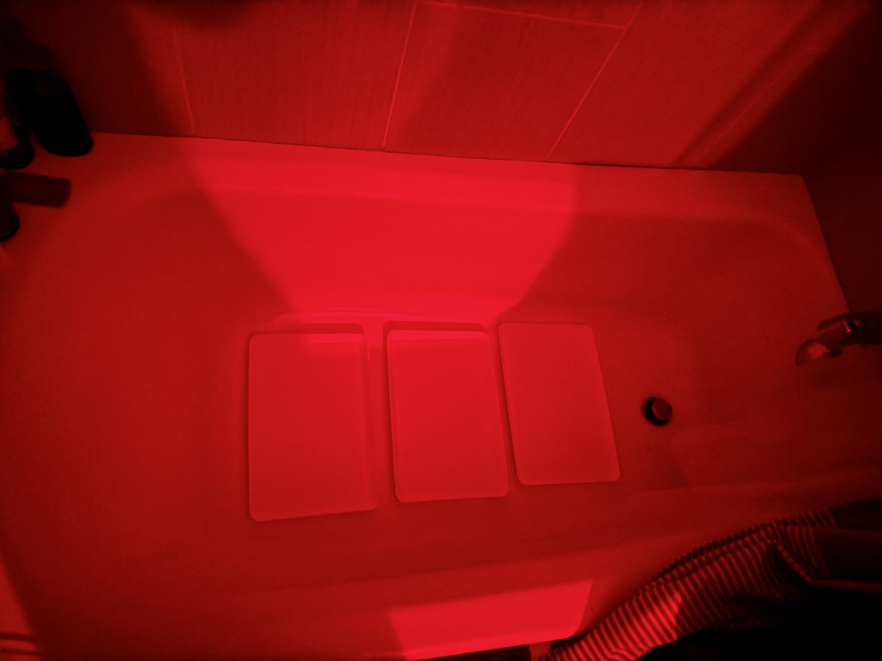
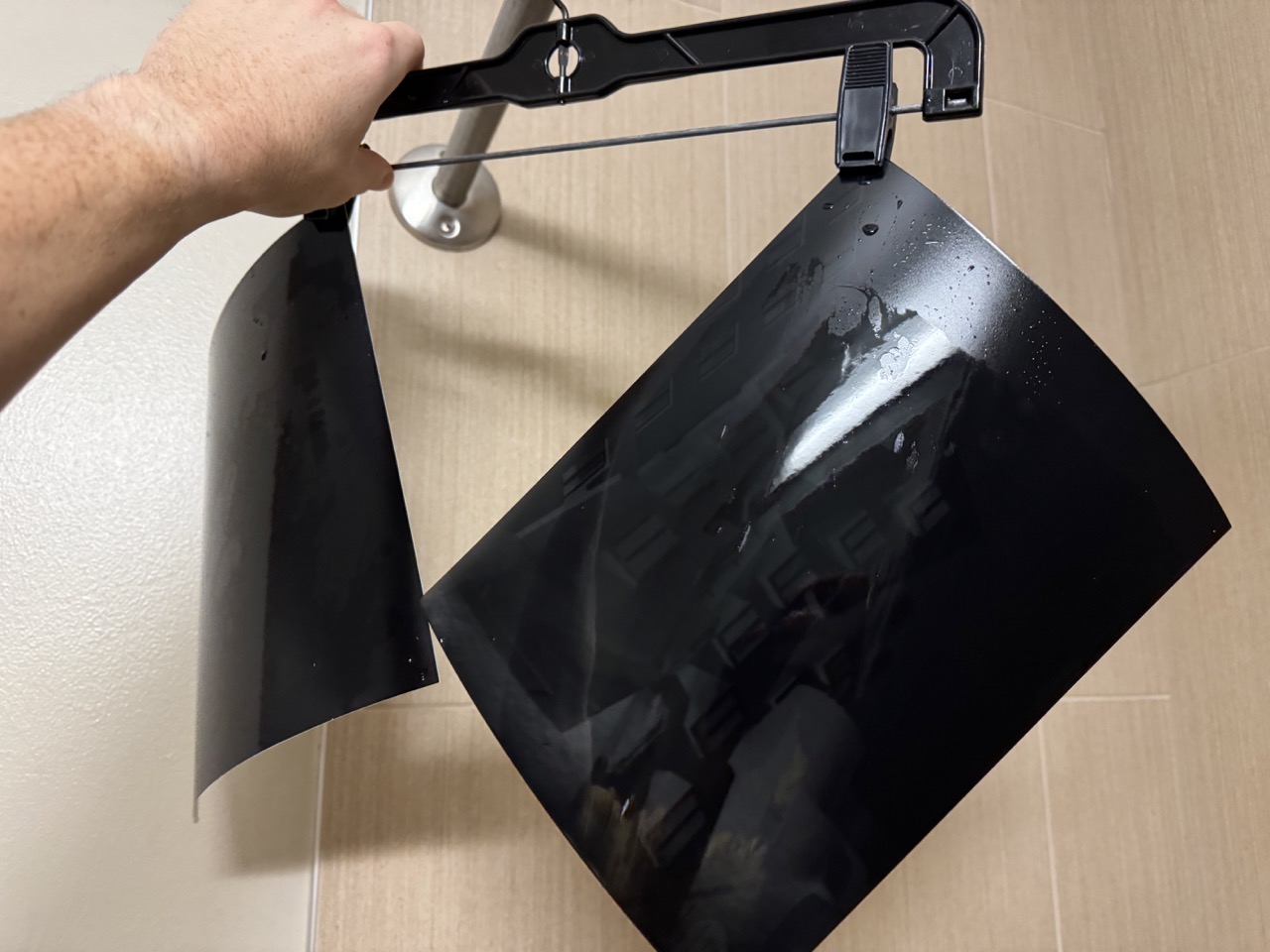
As I mentioned, I think I overexposed my negatives, explaining the extremely dark color.
Because the camera produces (inverted) negatives, one must contact print to obtain a positive.
This shows the process of exploring different exposures for the contact print so you can decide how dark you want your final positive to be. I explored a few different timings, but found 13 seconds under my iPhone flashlight to work pretty well.
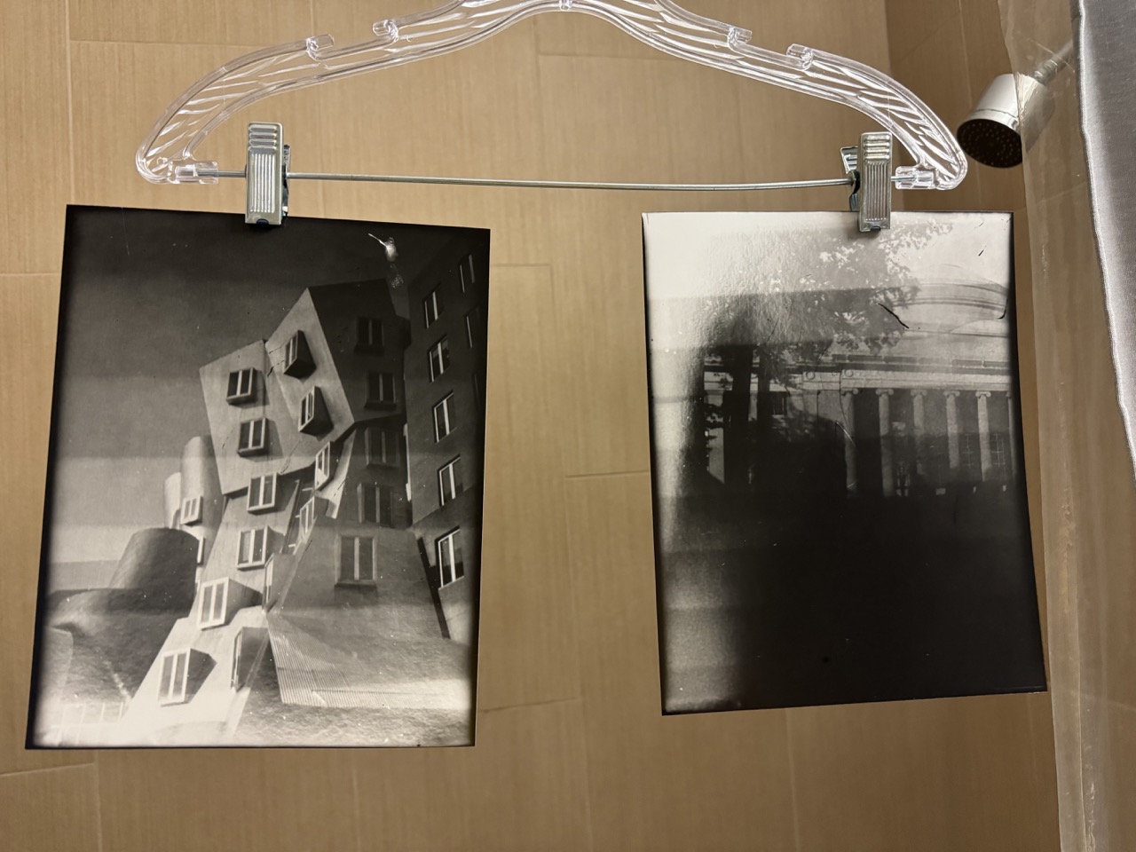
I ended up with the following prints. In hindsight, the 16x10 doesn't work super well since the sides get overexposed when contact printing, but I will have to test again with a better exposure. However, I truly am impressed by the photo of Stata.
Comparison to reference: