This week I decided to work on designing the PCB for my final project.
I have tentatively set my final project to be an autonomous solar powered boat for environmental/water quality monitoring.
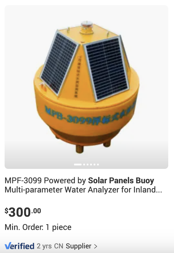
Current solutions to river water quality monitoring include using solar powered buoys. These are expensive, however, costing more than $300 and can only monitor a single portion of a large lake.
For this week, I wanted to design a printed circuit board that would, via RC (radiocontrol), communicate to a remote that would control its directions.
The boat for this week should be able to 1) communicate to a remote control, 2) record and transmit its position, 3) know its orientation, and 4) steer appropriately.
The components needed include:
1. Remote Controller
2. Transceiver module. Using NRF24L01 for now (to be replaced by cellular/satellite later). 8 pins.
3. GPS Module. Using ATGM336H. 5 pins.
4. Compass Module. Using QMC5388L. 5 pins.
5. Raspberry Pico W Controller. 30+ pins.
6. 2 BLDC motors, 2 ESP controllers. 3 pins each.
Also in development will be a solar charging battery circuit, but this is purchaseable off the shelf and does not need a PCB.
Future iterations to the boat will include replacing the Transceiver module with a cellular / satellite communication module.
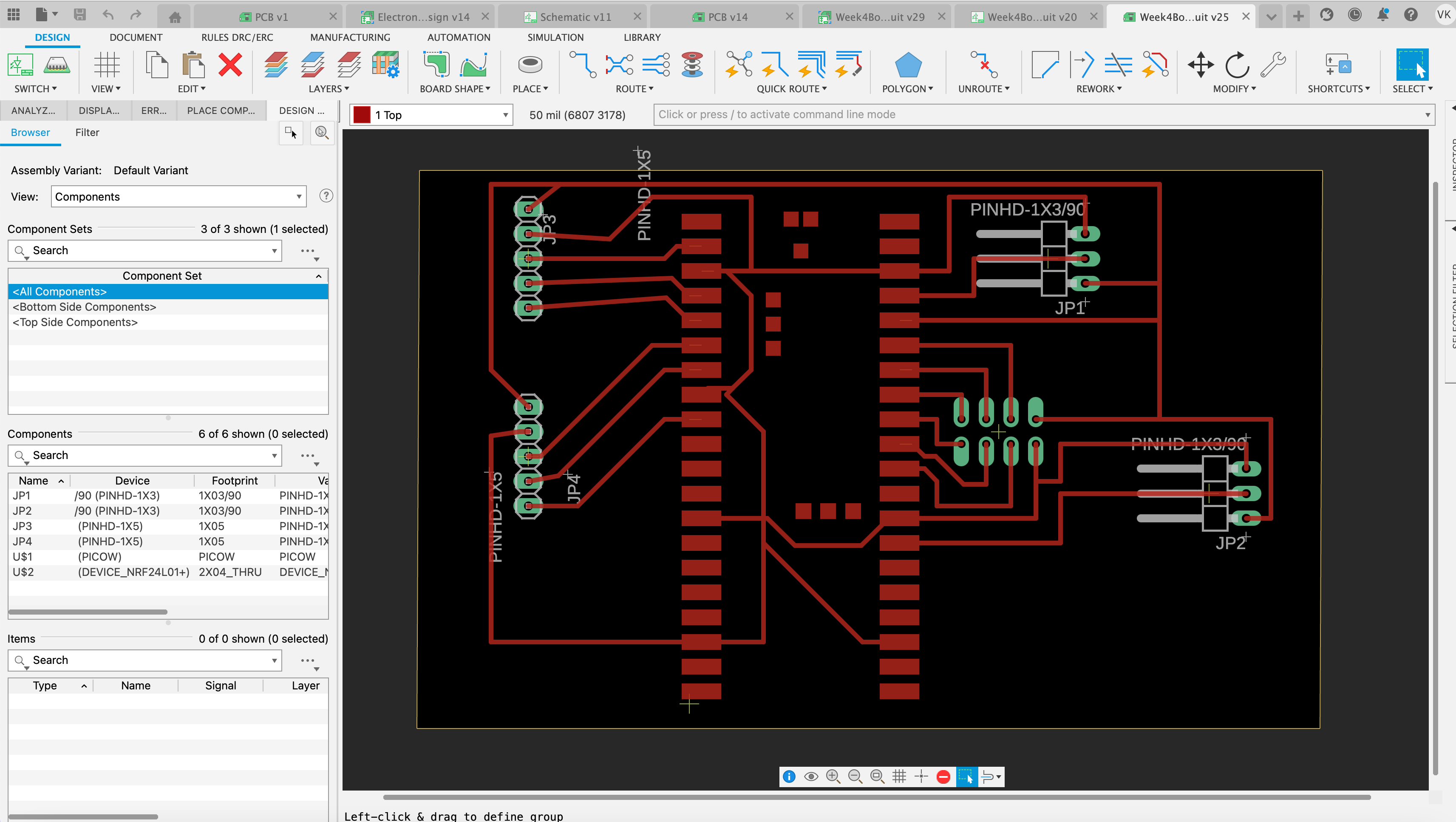
Using eagle, I designed an initial routing of the components. I connected the various components to the board via pcb traces, and ensured that the holes were the correct size (03/90 inches) and that the traces were also the approriate width, at 1.6mm.
Here is a photo of my circuit board. The 5 pin components represent the GPS and Compass each. 3 pin components represent the ESC modules. The 8 pin component represents the NRF24L01.
A downloadable fusion file is available here