Week 8 - Input Devices
-

Electromyography (EMG)
My final project idea at this point is to work with prosthetics. While engineering the prosthetic hand itself might take a while, one of the "cool" features that I am hoping to implement would be controlling the motion of the robotic hand by reading signals from an actual hand.
This week I was trying to explore more how EMG sensors work and whether I can make something similar myself from available to me materials. To me this idea at all sounded a little impossible, but Anthony was able to guide me through it and make it quite real. -
Planning and breadboard prototyping
One of the first steps was to understand how I can engineer something like an EMG sensor. I researched online different DIY solutions, and decided to follow the path of implementing EMG using an OP-AMP.
The image on the right side is a rough overview of how the system should be looking like. There are two points of signal input from the muscle (represented as mus1 and mus2 reapectively), resistor that controls the gain of the signal, capacitor, reference contact for knowing what is the overall voltage of the body (represented by a coin).
Drawing is courtesy to Anthony (so is me understanding the overall design).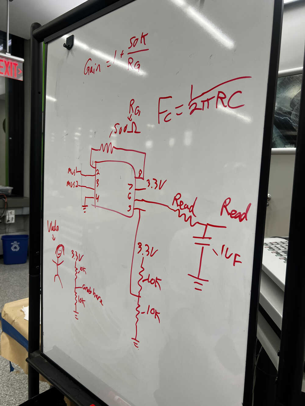
-
Breadboard testing
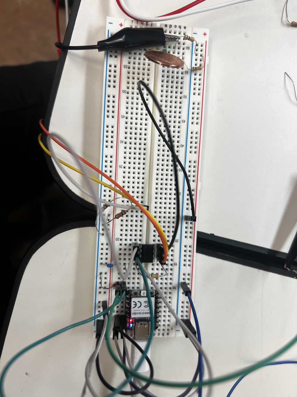
First steps in understanding and testing the scheme was prototyping it on a breadboard.
I decided to use Xiao-RP-2040 as a microcontroller for my design, mostly since there were the most available, and I had no special requirements for the microcontroller.
Here is where I understood the main difficulty of EMG - signal is extremely hard to capture. I was hoping that I can acquire signal for each separate finger if I search it carefully, however, even getting signal from bicep was hard.
My design included a way to cutout the frequencies that are definitely outside of the reasonable range, however, signal was still hard to read. Sometimes it worked and I could see a little bit of signal on the screen of the osciloscope.
Since the system was occasionally working and occasionally not, I verified for myself that the design is approximately right (with maybe some of the resistor values to be adjusted), and I could go ahead and design and mill the board, so that I get more reliable results. -
Designing and milling
After a few boards designed over the course of the semester, milling one more felt easy. I still got to struggle a little bit since the milling machine I used before was taken, and I needed to learn how to use a different one, but overall it wasn't an issue.
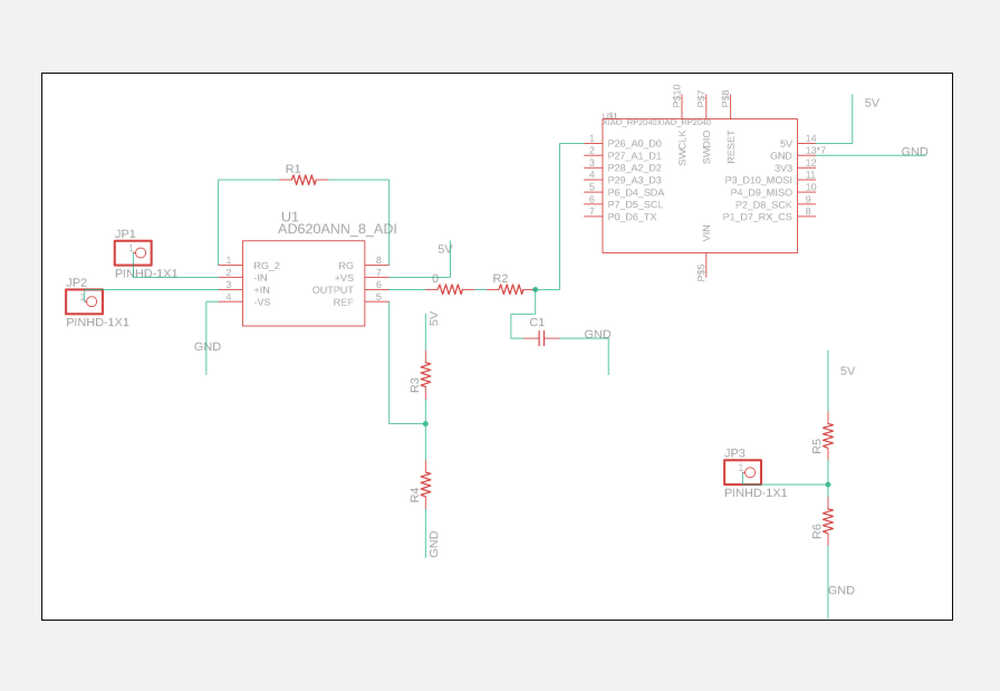
The manufacturing file can be found here, with an approximate screenshots being on the right.
The printed board and soldered board pictures are also on the right. On this step, however, I already had a few oopsies (which I would have corrected if I was remaking the project, but it didn't affect the functionality):
> Drilling holes ended up non-trival, a Gerber file that got fed into mods project ended up not having some of the holes, so I had to improvise with how to solder an OP-AMP.
> I chose an incorrect outline for the capacitor, so I had to use a blue one that is probably more intended for breadboards, instead of a small one.
> Also, I didn't really know that the pin holders are supposed to be soldered to the other side (I tried to fix it later, but it ended up being even worse because little parts of the connections were damaged).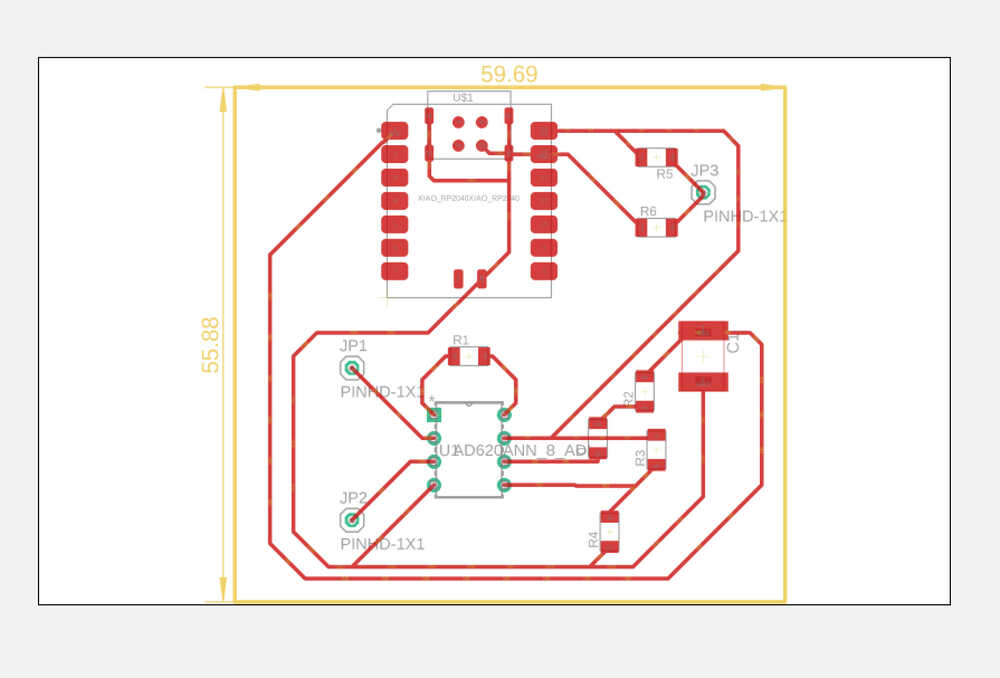


-
Keep testing
I have a lot of videos working and not working and trying to make it work. Inconsistency of the results is explained by unreliability of the signal received from the muscle and connection gel drying out to some extent. The last video shows the time when the system was working, as you can see and hear how, when I contract the muscle, the signal grows, and then drops when I relax my arm. The difference is on the order of 250 for relaxed and 500 for contracted, although, of course, these values would vary for different muscles, contacts, and people.
The "coin" system was replaced with a third (black) connector, mainly for the ease and consistency of the connection. -
Conclusions
This was overall a fun project, with its own difficulties, but also a nice peak into how medical devices and work and what is the bottleneck of those.
Thank you to Anthony for guiding me through the project and helping me with the design and understanding of the system.
Thank you to ChatGPT and Github Copilot for helping me with writeup!
The code for reading the input is super trivial (just reading a value from the pin), but please find it here for reference and reproducing..gif)