 What I started with
So, I'm making an electric bass guitar. Not sure why because I don't even play the guitar, and I'm pretty sure I've never held a bass guitar before.
But during week #8 I got the spontaneous urge to make one since my bassist friend has been using an old guitar during our jam sessions. Oh and I listen to a lot of funk and I want to learn those sick basslines.
*graciously covered by the class budget or inventory
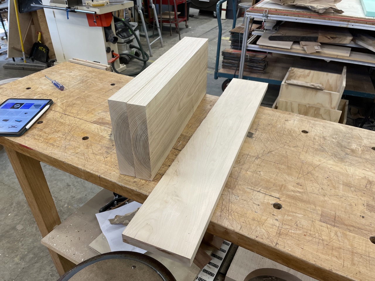
...And some $19.43 of maple (neck + fretboard) and $20 of ash that was payed for using MakerBucks that MIT gives every student so I'm not counting it as an expense. So in total, under $50 for a guitar. Nice!
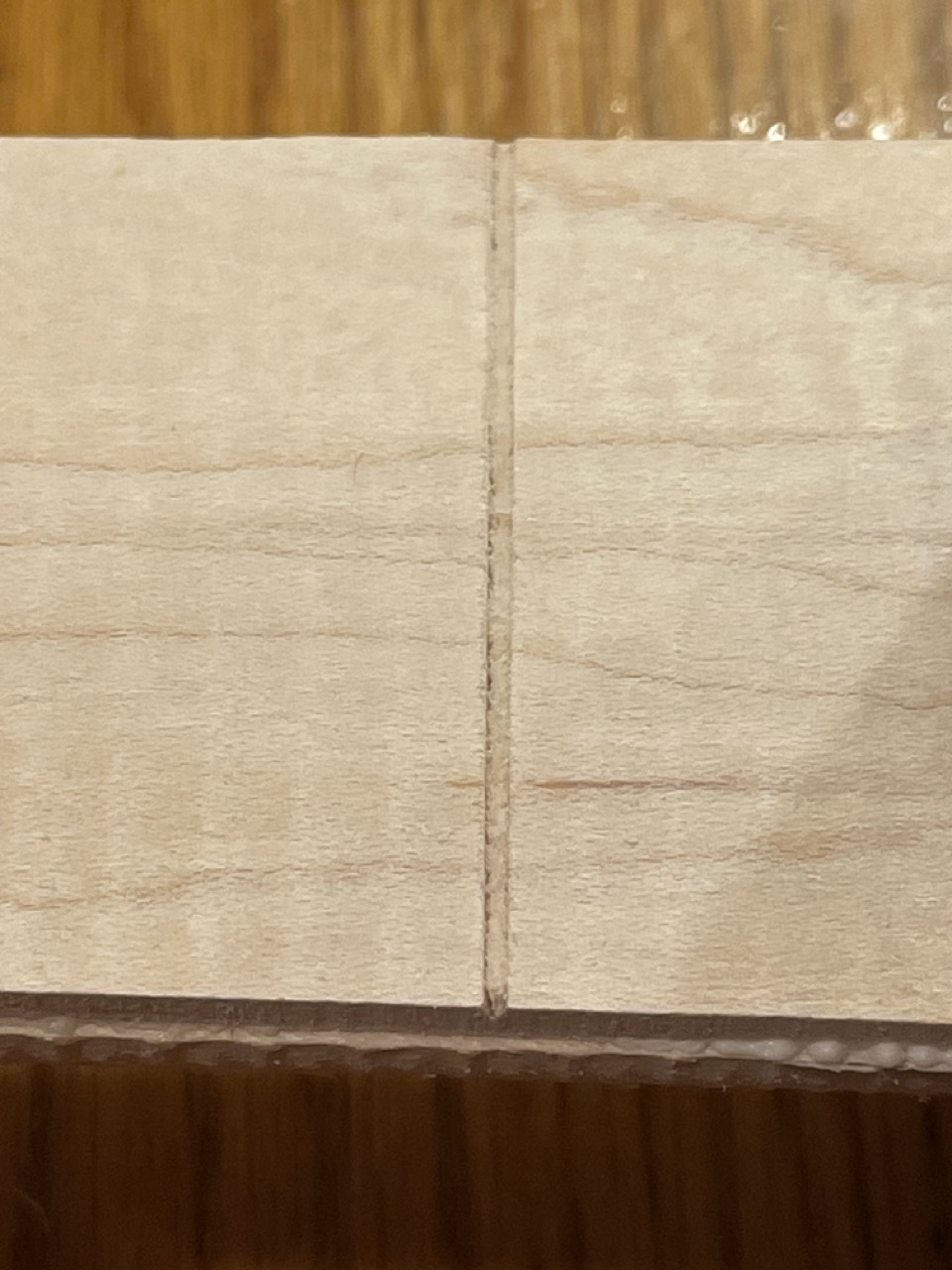
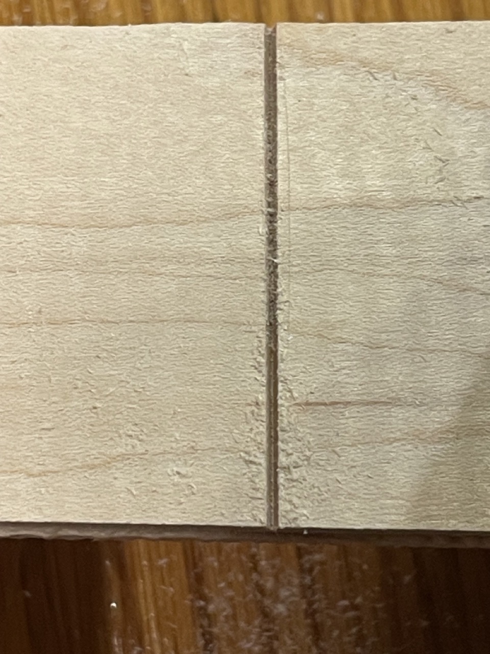
The stock for the body is quite large (15" x 22" x 1.75" minimum) and wood that size is very expensive. So I started by gluing two long pieces together. Make sure they are planed and jointed or this will not work.
What I started with
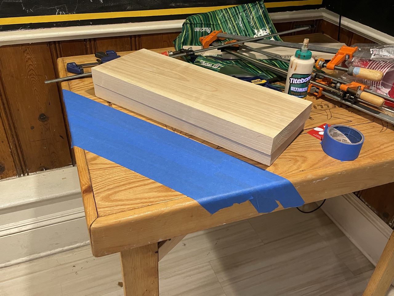 Masking my table so I don't glue it to my blank LOL
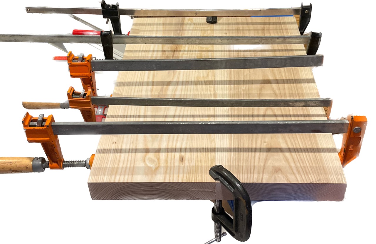 Clamps on the two axes that matter
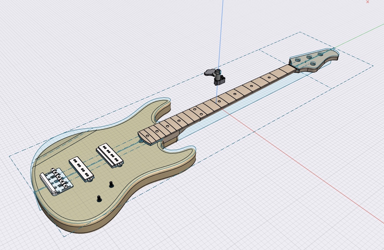
I modeled everything in my CAD program, Shapr3D. For a guitar, there are some challenges involving its organic-ish shape while maintaining tone precision (if it's pretty, but plays out of tune, then there is no point). Thankfully, there's a tone of specifications on luthier forums and vendor's websites. So, I started with a bounding box sketch of the guitar:
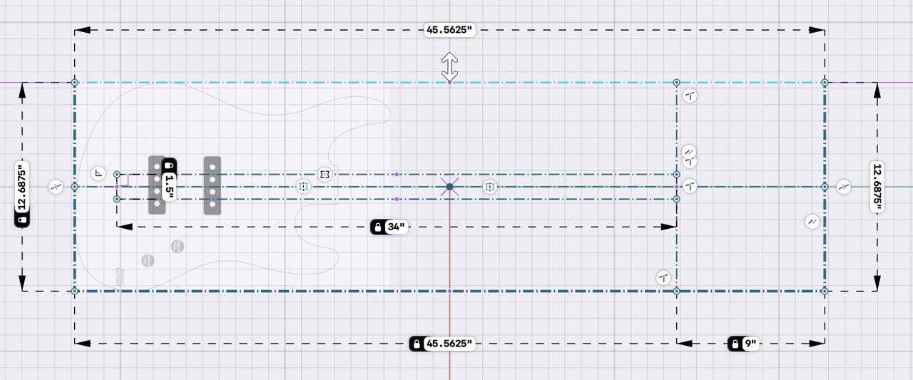 Dimensioned is the total length and scale length (bridge to nut)
Then, I'm combining reference images of guitars I used as inspiration; for the body, I really liked the contour of Ernie Ball's Joe Dart II; and the headstock is based on the StingRay. Oh and the frets are calculated using a fret calculator.
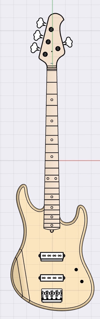
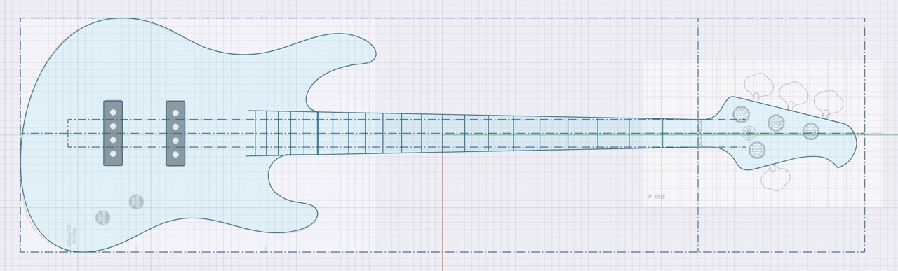 Complete sketch of the bass' top face
Tip: Dimension all distances from the nut in your CAD software, as opposed to relative which will make mistakes harder to spot.
Now for surface modeling (2D -> 3D). The neck seems complicated but is surprisingly trivial. Since I have no clue what a guitar should feel like at any point along its length, I started with a known a profile sketch of the "Modern 'C'" neck at the 1st and 12th frets. Then, the "loft" operation magically creates what is otherwise very organic geometry:
The headstock is then connected to the rest of the neck using the same method. Let's look at some more CAD techniques: the body of the guitar is mostly flat but its left-hand side is where the player rests their elbow, and a square edge would be rather uncomfortable. So, I'm using a subtractive extrusion and fillet to create a nice resting curve.
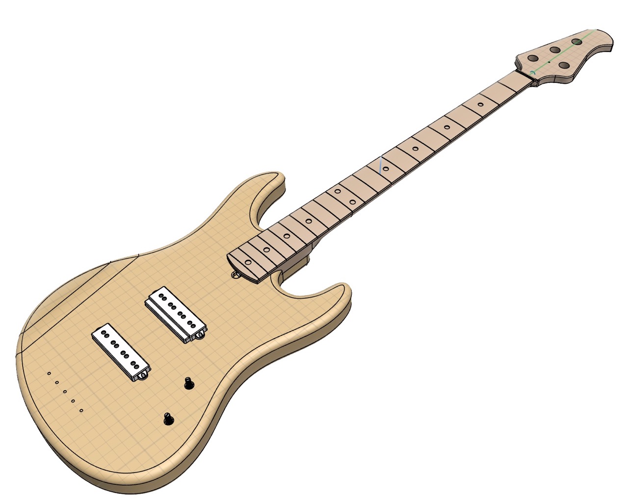
Similarly, the guitar needs smoother geometry where the player will be pressing their chest. On guitars, this looks very organic and complicated but a simple subtractive extrusion of a circle at an angle can recreate this very easily:
Cool! Let's look at what we have so far:
Next I modeled the fretboard (which has a slight radius) and attached the headstock also using the loft operation.
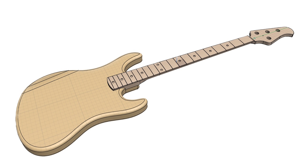 Complete guitar minus all the electronics
There's also a long piece of steel, the "truss rod," which goes in the neck and is sandwiched by the fretboard. This is used for compressive strength and its curvature can also be adjusted to compensate for the force exerted by the strings (otherwise the neck will bend in either direction and the guitar is unplayable).

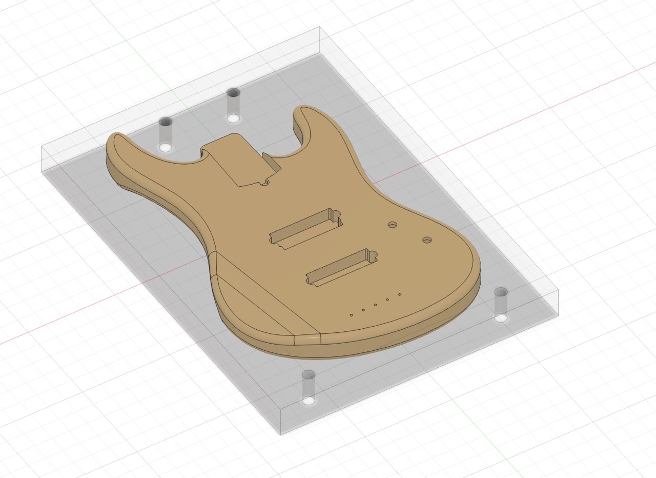
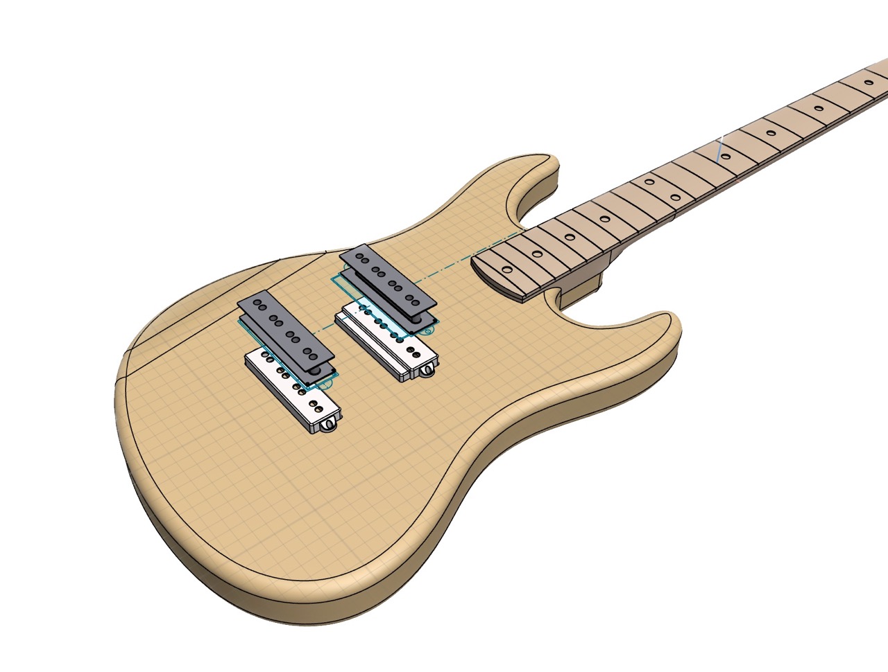
Finally, I added some cavities for the pickups and electronics (control knobs and all the wiring in between).
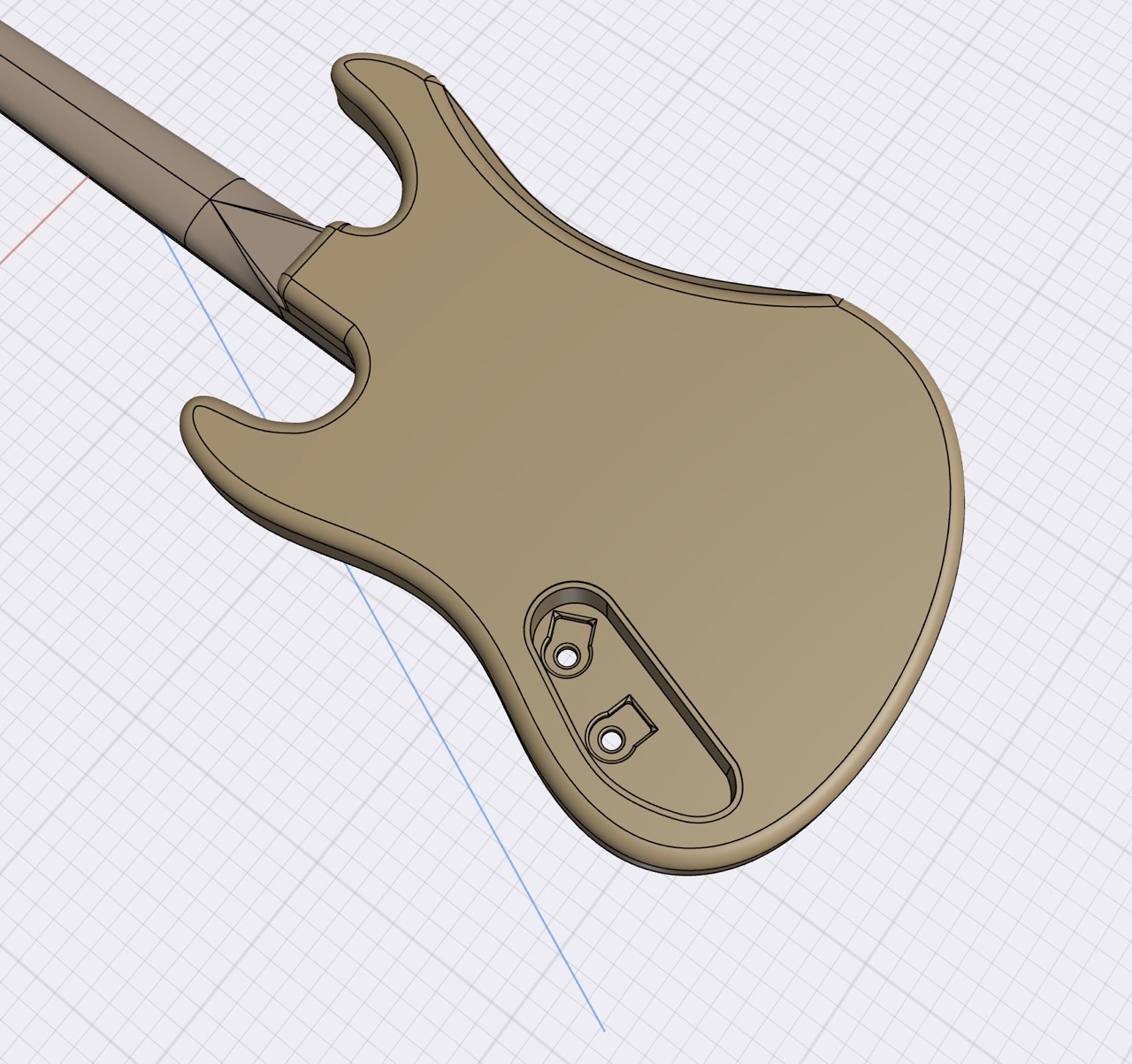 Bountiful space in case I want to add more stuff here later
 Place for the pickups and pilot holes for the bridge
And here is the complete CAD of the guitar!
In this age of digital fabrication, you'd think making involves creating a design and pressing "print." But with subtractive manufacturing, there's an entire suite of tools involved that will tell the CNC router what to do. In my case, that's Fusion360.
For both the body and neck, I needed to machine both sides so I used guiding holes to get the alignment perfect. On the first side, the machine bores 5/8" holes all the way through my stock and slightly into the wasteboard. Then, I hammer dowels in and the flip side of the blank back into those holes. This gave me (literally, as far as I can tell) perfect results.
 Four symmetrical holes for alignment later on
Then, I need to account for the contour; simply drilling it out would make my stock droop midway and eventually break free (the machine will happily send 10 kilos of wood across the room = catastrophe). So, I added tabs using the built-in option of Fusion360's 2D Contour.
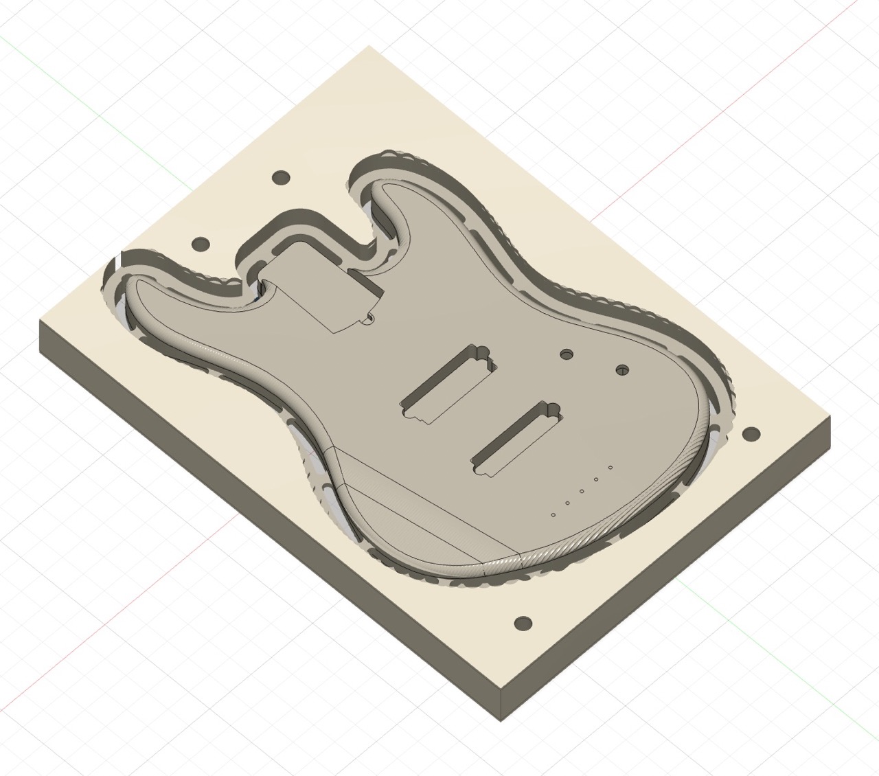 Tabs that I then cut out on the bandsaw
I'm glossing over a lot of the details here, but learning CAM was a really really long process. Having the intuition for it and getting a feel for the right spindle speeds and feed rates is initially tricky, but I learned by making every possible mistake and being pointed in the right direction by Anthony. I'm using a 3/8" endmill for the majority of the job, and altogether a guitar is about 5 hours of just machine time.
At a glance, the process I did for all three jobs (body, neck, fretboard) involved a 2D facing operation (very quick feed speed, large endmill and overshoot is OK), 2D contour and 3D parallel path. Of course, this isn't right for every design but worked quite well for my guitar.
So, I've now got a really thorough design of my project but it's all digital, and I can't play that!! You'd be surprised how much of this got started in the four days before submission day but here we go.
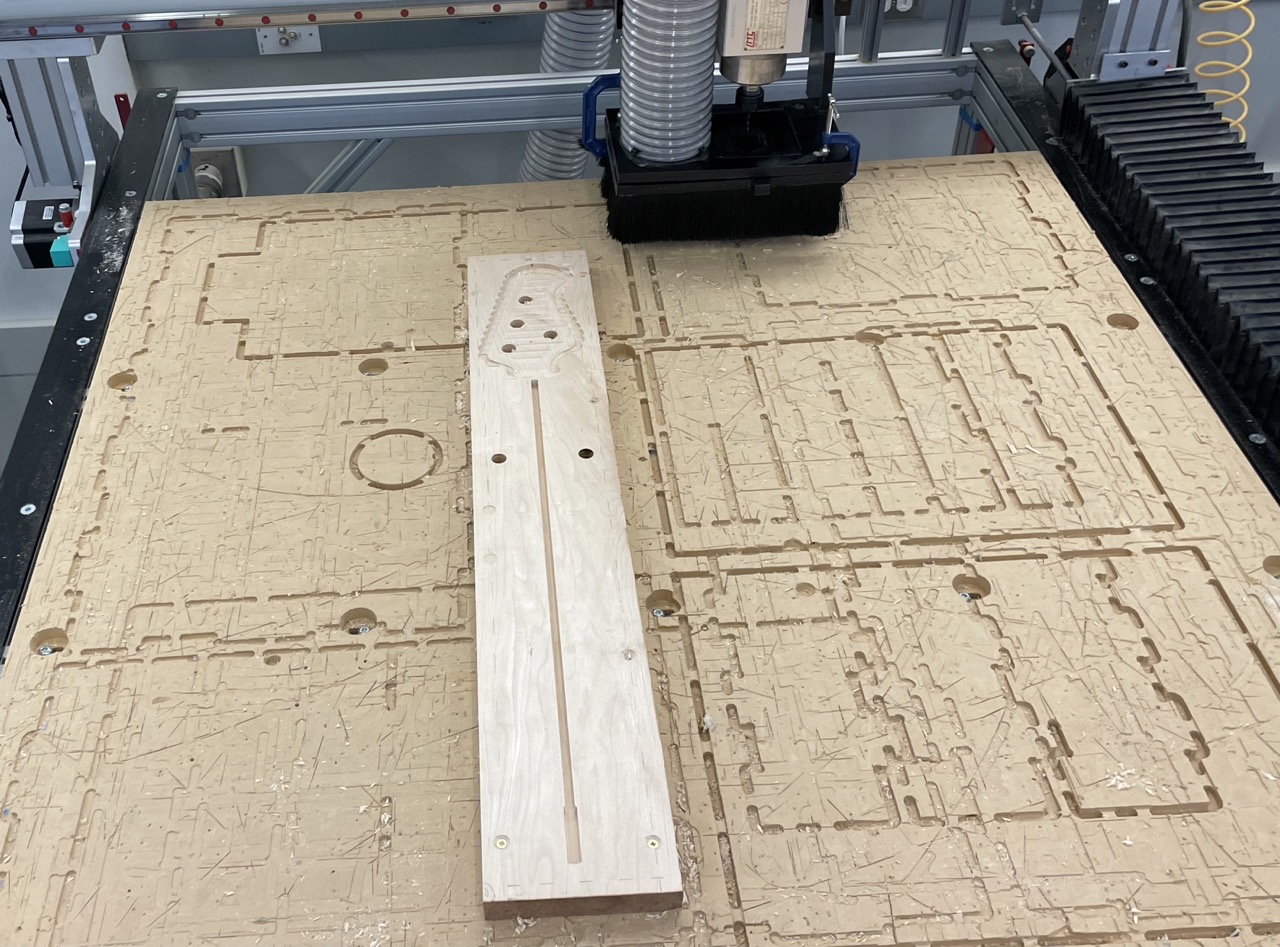
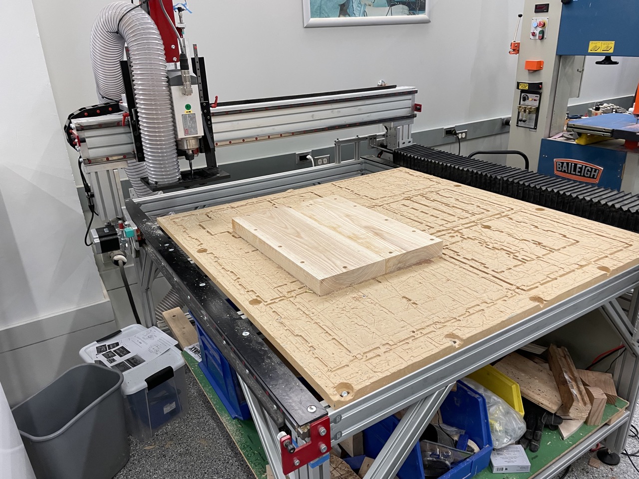 Blank drilled into the CNC router
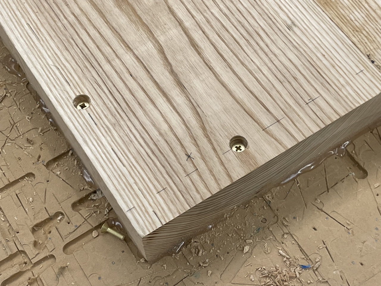 Brass screws at known measurements where the machine won't collide
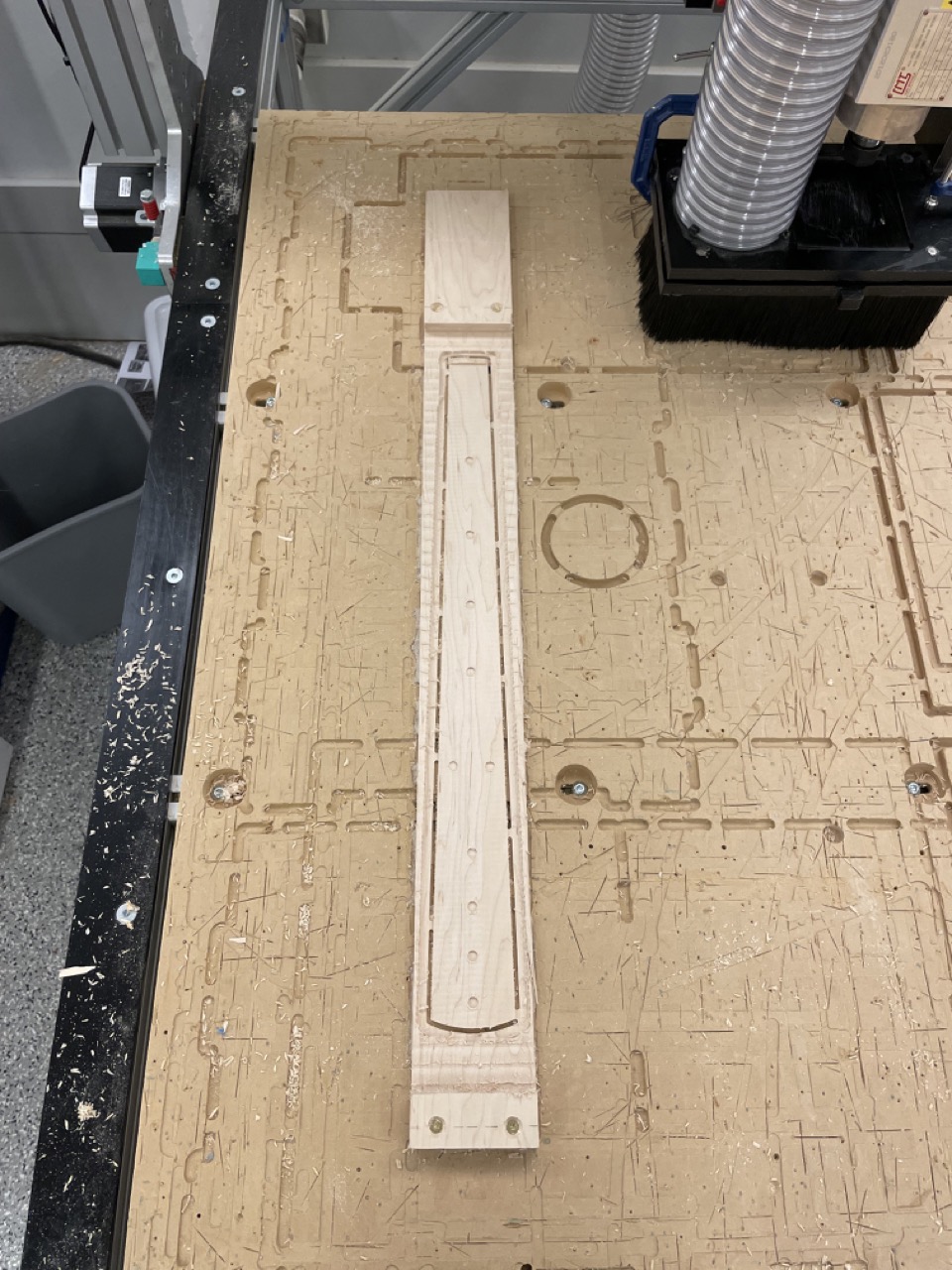
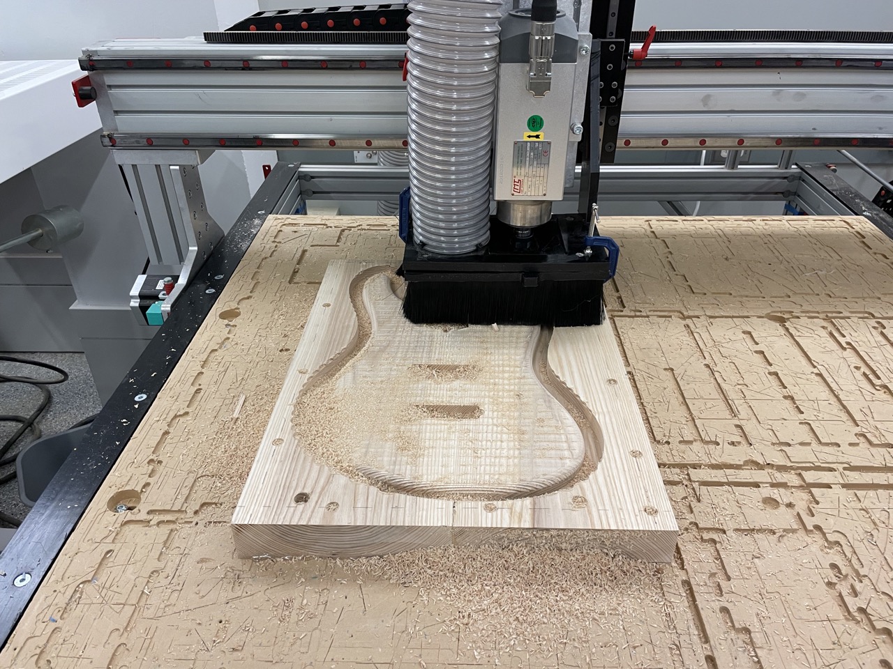 First side of the body in progress
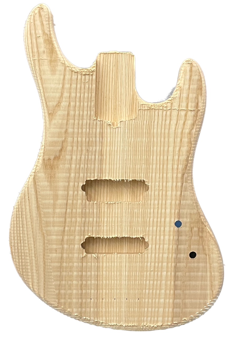
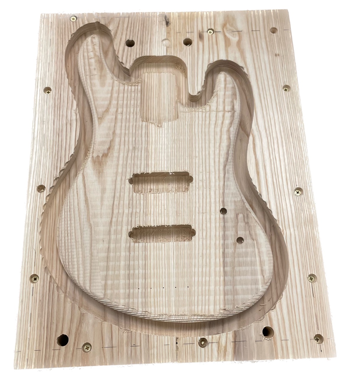 First side of the body, done! Note the four 5/8" holes for alignment
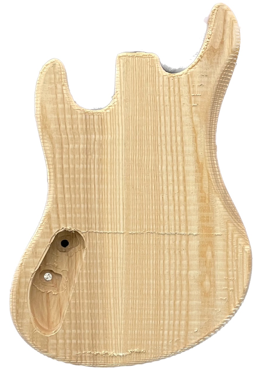
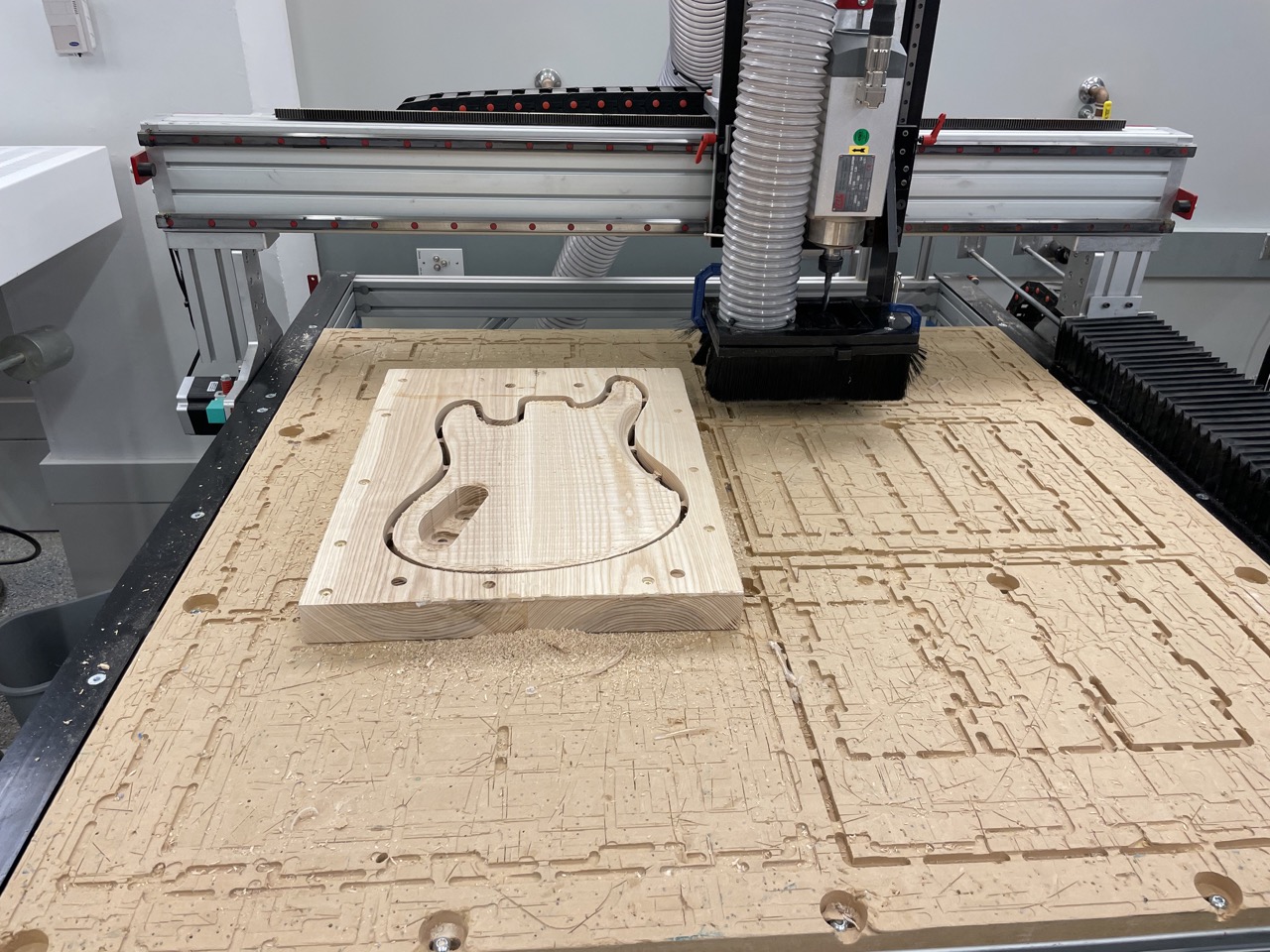 Backside of the body, done!
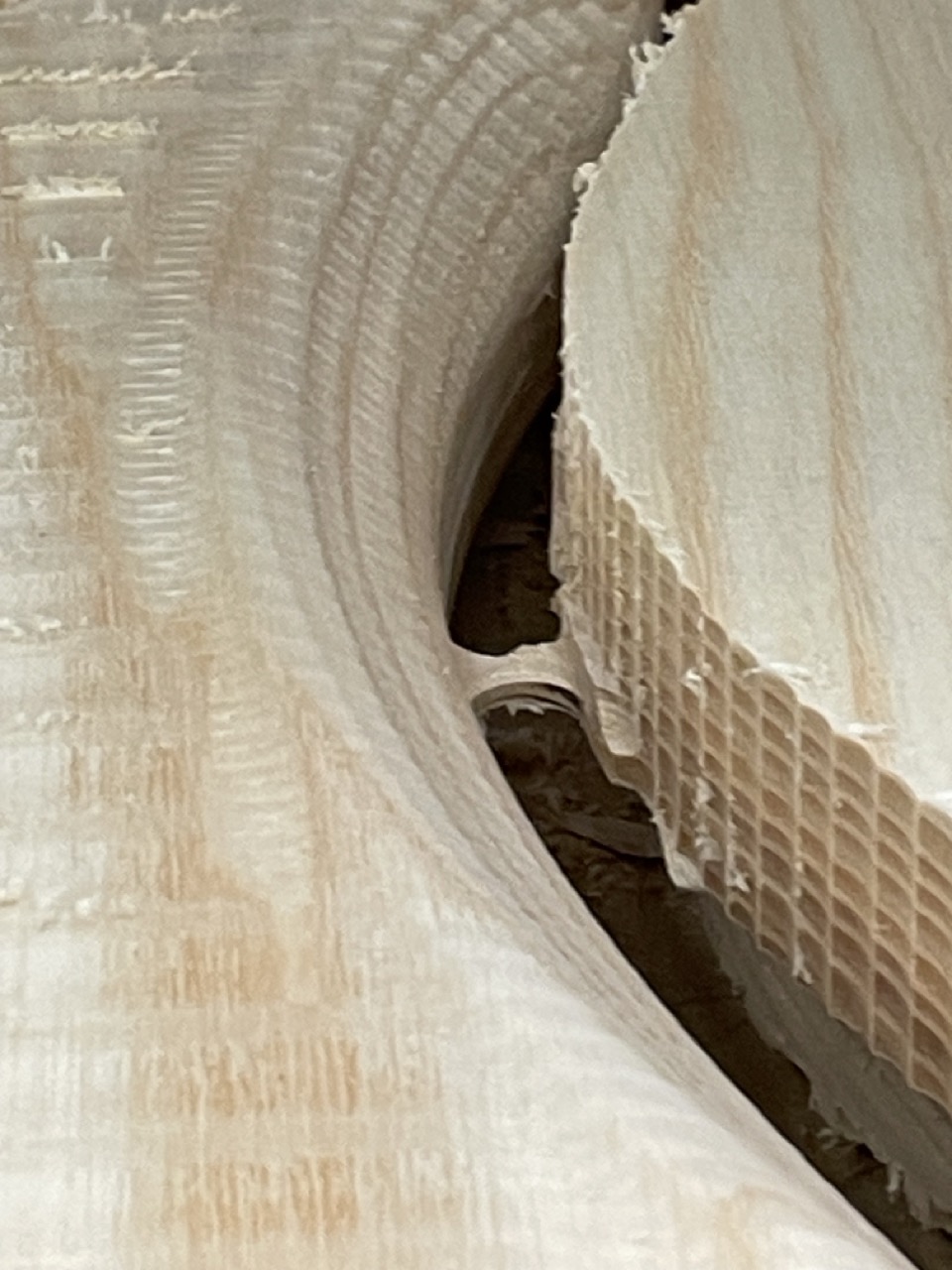 The body is low key holding on to the stock with thoughts and prayers, but it worked!
Some 2.5 hours later, you have a guitar body!
The neck is also double sided, so I followed the same exact process.
 Front side of the neck
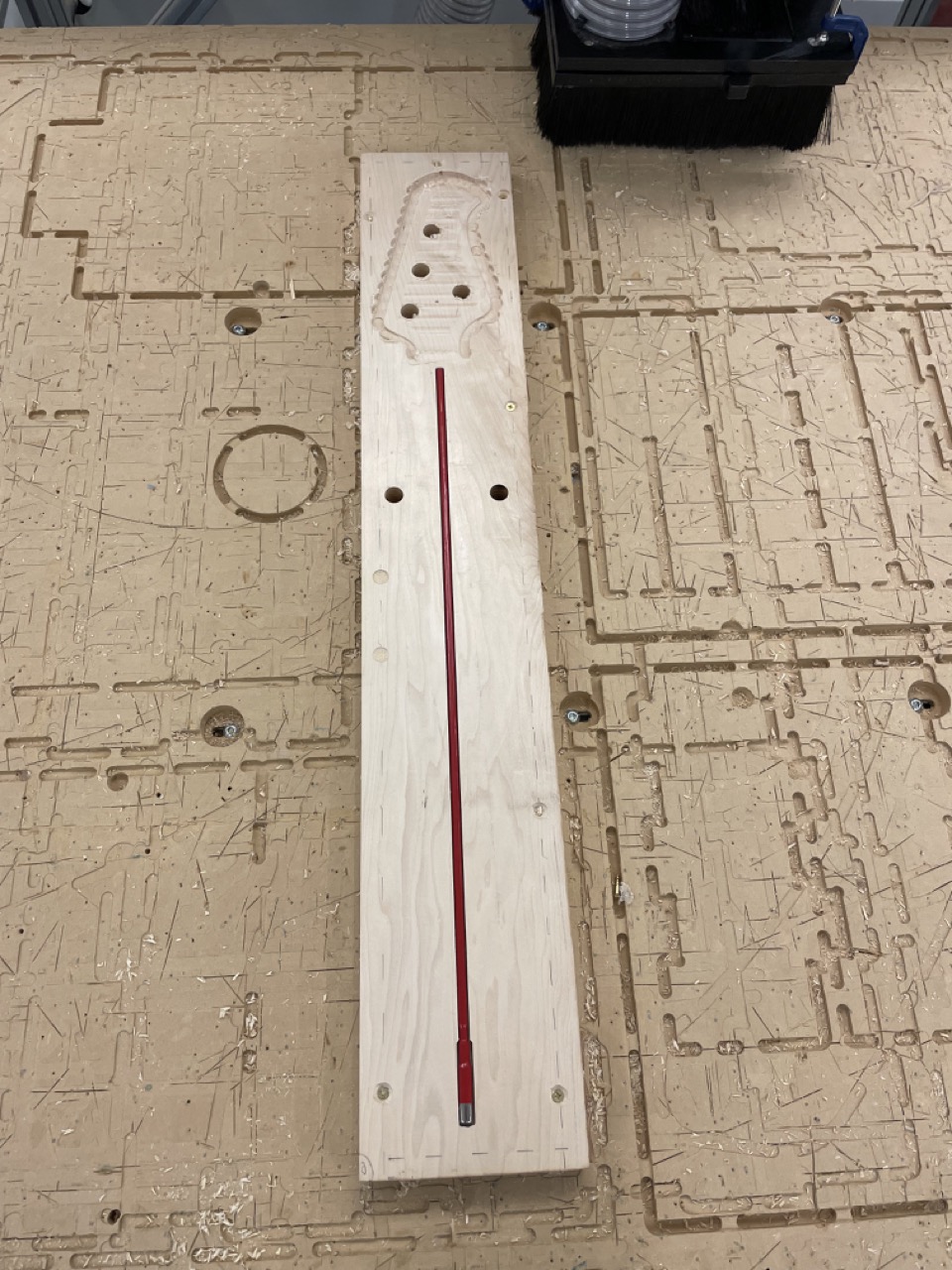 Testing for alignment of the truss rod and re-milling is very hard later, but easy now!
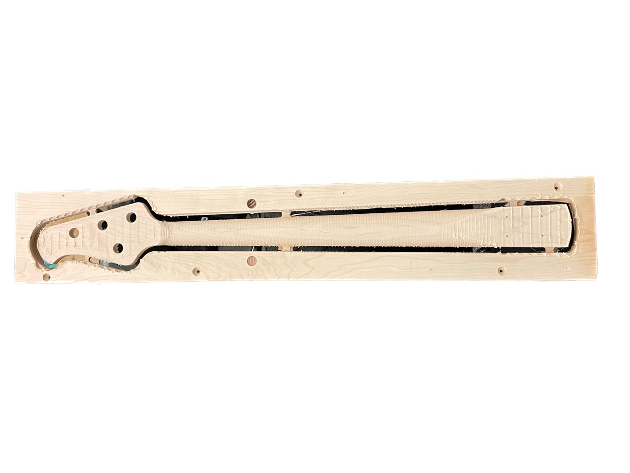 Neck, done!
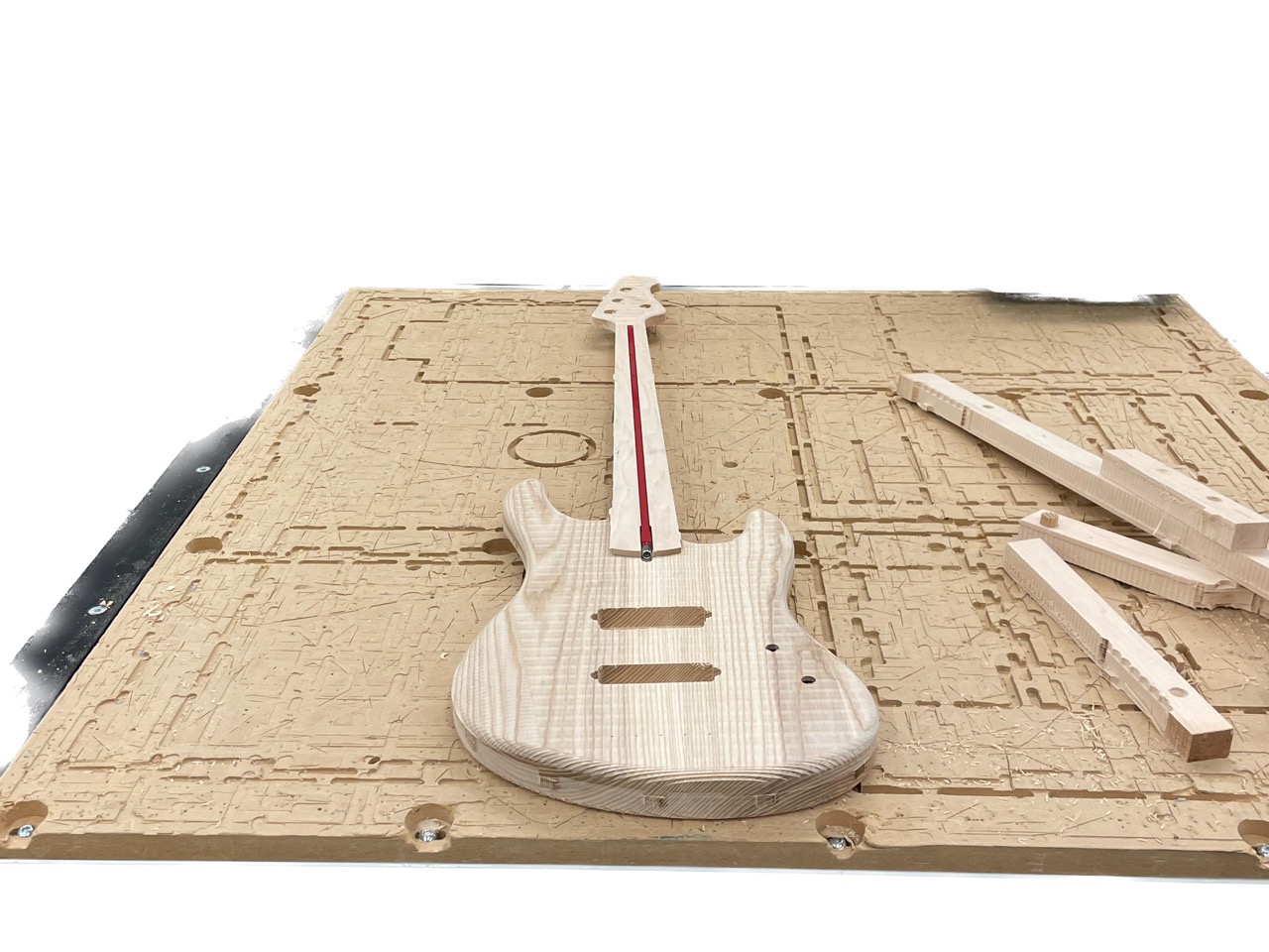 Everything fits together, very exciting!
The fretboard is single-sided, which was less work. I made sure to use the planed side for both it and the neck, because those two will be glued and you don't want machine marks there for a strong joint. I'm also using hot glue to keep it in place at the sides since my stock is too skinny.
 Fretboard in progress
The frets of the fretboard were cutout using a 1/8" V-Bit, which also worked nicely. I cut them at a starting depth of 0.01" to gradually went up to 0.05". For my machine, conservative feed rates of 15 IPM at 12,000 RPM worked fine.
 Fretboard done but, wait... where are the frets?!
The V-Bit doesn't have flutes like an endmill, so debris aren't evacuated that nicely and the frets appear deceivingly shallow. But don't be tempted to just dig deeper, as a knife will clean those cuts up nicely.
 Fret, just machined
 Fret, after cleaning with a X-Acto knife
Oh yeah, things are cruising and it's a whole 32h before the deadline! I started by gluing the fretboard to the neck. Of course, the truss rod is in there too but I used masking tape to avoid gluing that too otherwise bending adjustments would be impossible.
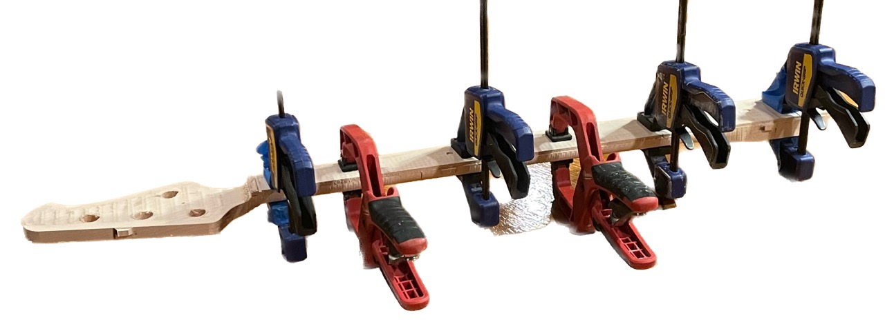 The right amount of clamps is N+1 clamps
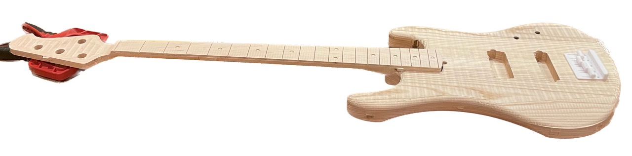 What we have so far
 Starting to look legit!
I need to drill holes the output jack and a route between the pickups and control cavity. In one instant I could be ruining the past 100 hours of work.
The output jack was bored on a drill press using carving bits of increasing size, so it was actually pretty safe.
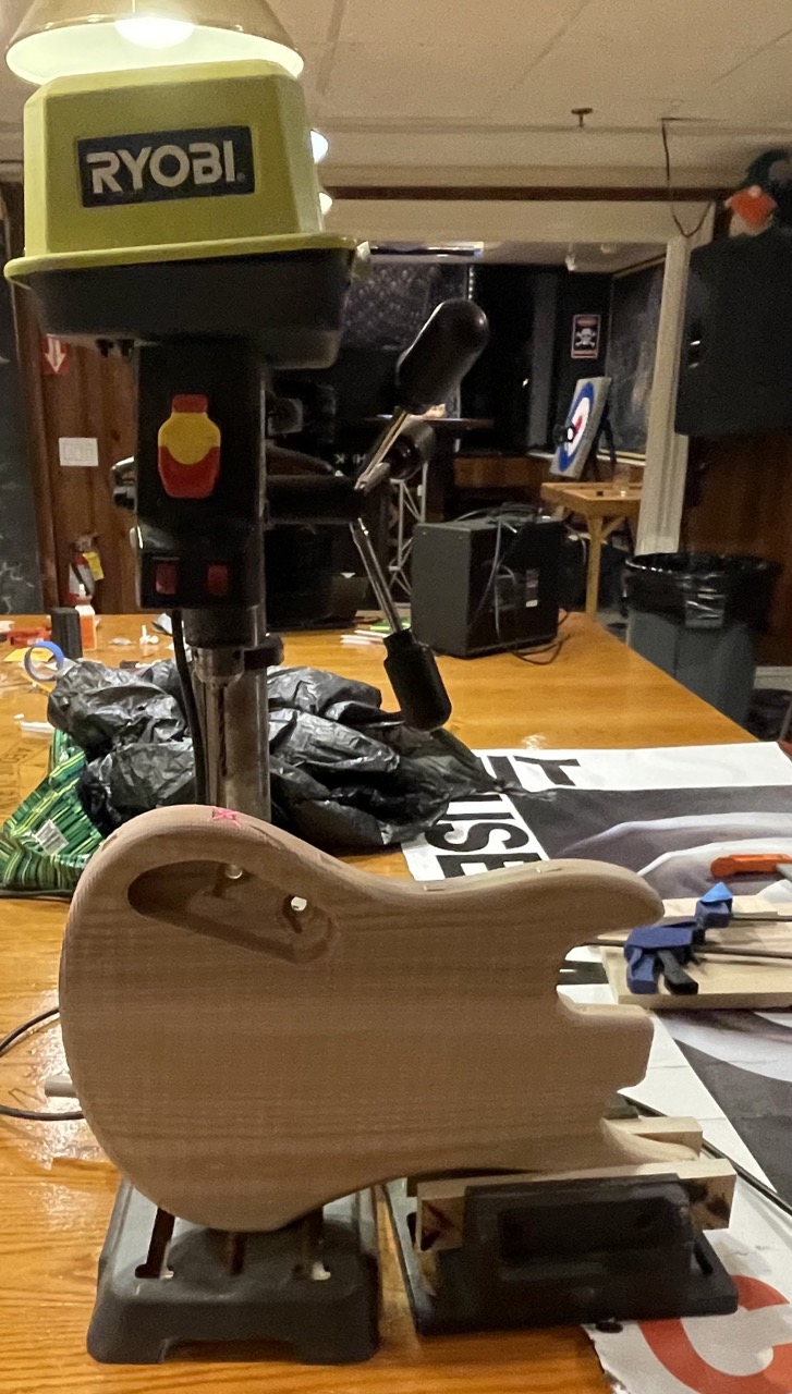 Note how I'm clamping the guitar to distribute the force and avoid damaging the wood
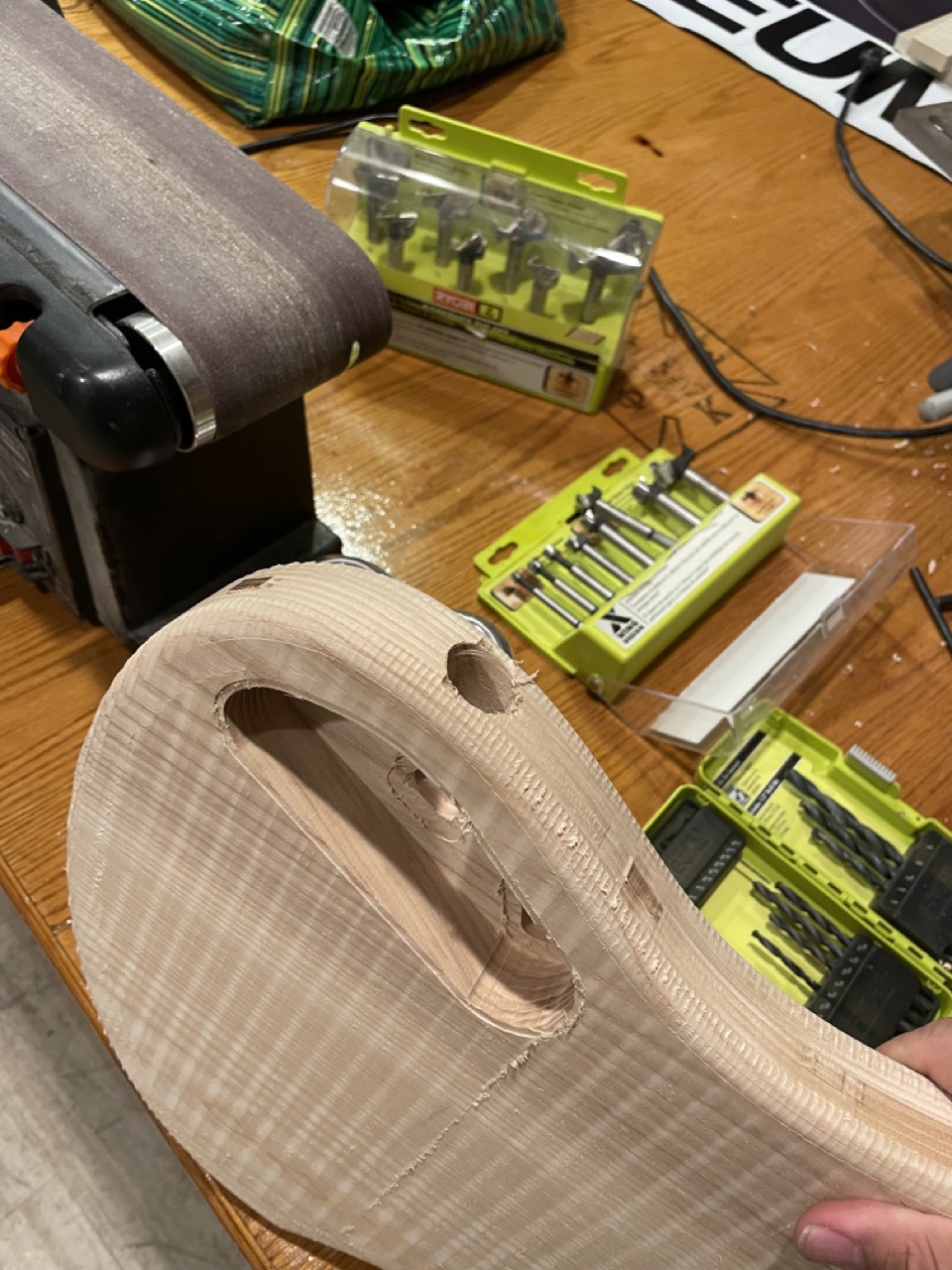 Result is exactly what I wanted, phew!
Now it's time for "the route." The right tool for the job would be a long, somewhat flexible drill bit but all I had on hand was a mason bit. It took ages to carve through that much wood.
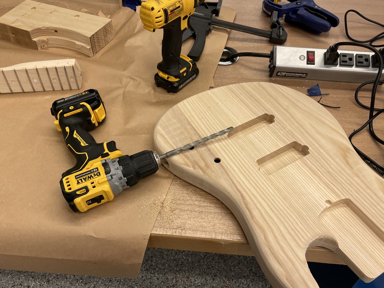 The Route™
This process was incredibly stressful and I was half a centimeter from ruining my guitar but it worked!
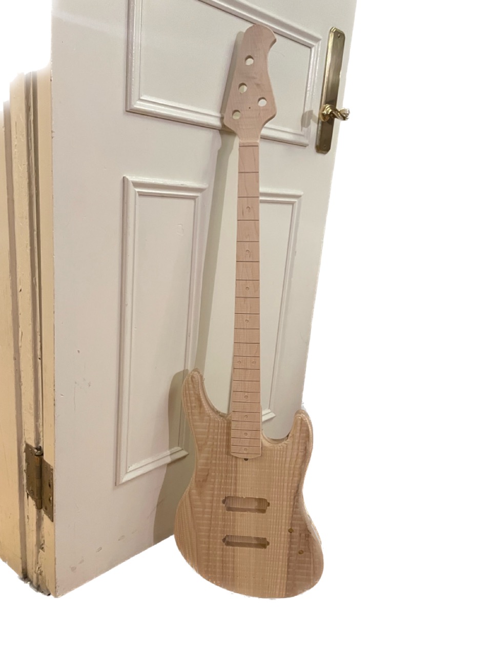
Now for my absolute favorite part of the process: sanding. I spent a good two hours blasting music over my orbital sander as I sanded sloppy machine marks away and made this thing look gorgeous.
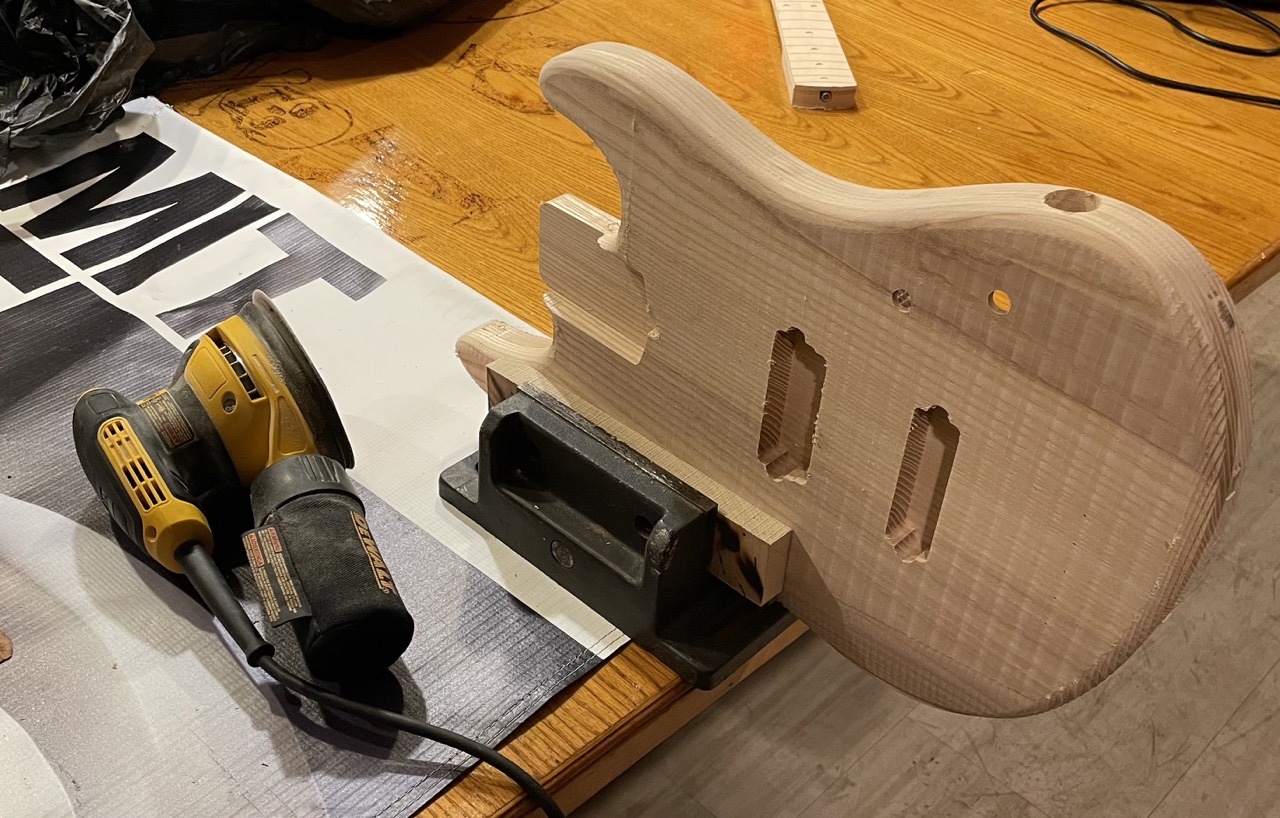 Sanding one face or edge at a time
I did a few passes of 220 and 60 grit sandpaper, and I can't overstate how happy I am with the results. Observe the difference between (most of) the past images versus the ones that are below.
During input devices, I made a couple guitar pickups. This involved creating a coil winder because my section doesn't have one of those nice CNC ones and I need around 8000 turns of 42 AWG wire (what I'm aiming for is ~8kΩ impedance). Conveniently that also fulfills the electronics requirement for this assignment, though I'm bummed I didn't have time to integrate other electronics in the guitar (notice how the top pickup is slightly larger than the first? hehehe).
I made a rotary encoder around the RP2040 Xiao.
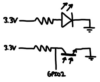 Circuit I'm making
This is pretty routine by now. I start by sketching the circuit on paper, design it in KiCad and mill it on the Other Mill.
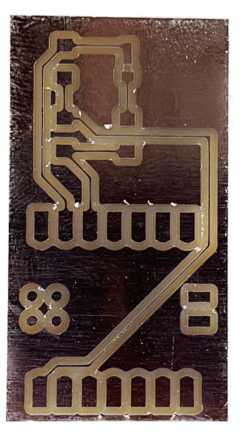 PCB milled almost exclusively with 1/32" end mill, so it turned out really nicely
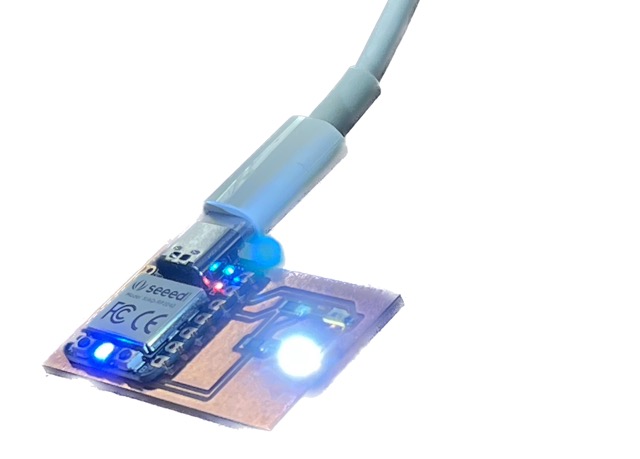 Everything assembled
This is a reflective optical encoder. It works by shining a light against a disc with a alternating reflectivity and a phototransistor in a voltage divider configuration is used to count rising edges (rotations).
I'm dividing the phototransistor with a 1kΩ resistor. Against white vinyl, the contrast is high enough to be picked up as a digital signal. So my code can use interrupts and becomes super simple:
#include <Arduino.h>

volatile int num_edges = 0;

void cb() {
    num_edges += 1;
}

void setup() {
    Serial.begin(9600);

    pinMode(A0, INPUT_PULLUP);
    attachInterrupt(digitalPinToInterrupt(A0), cb, RISING);
}

void loop() {
    Serial.println(num_edges / 2);
    delay(5);
}
I also double checked these readings against a mechanical winder. It was 100% accurate every single time I tried (yay!).
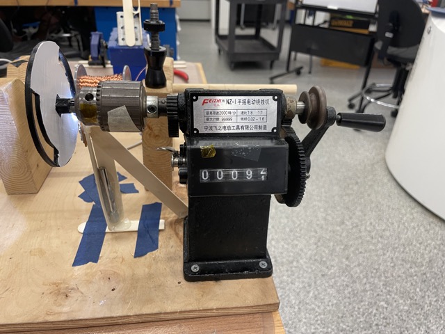 Baseline mechanical winder with rotary counter
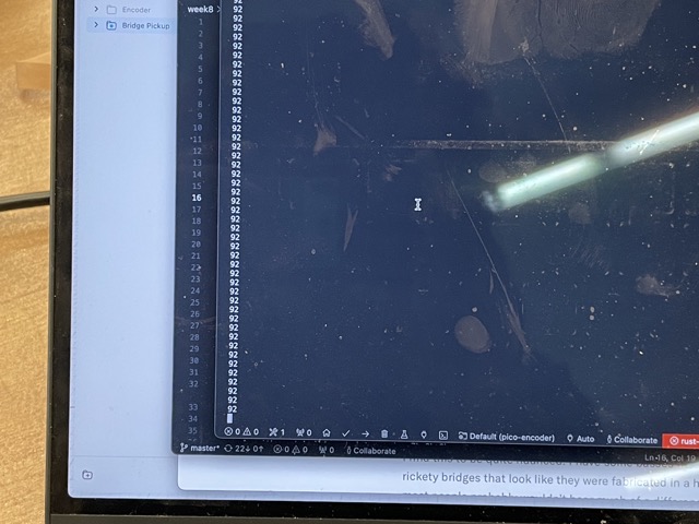 Versus what my rotary encoder is saying
Now, my first attempts turned out really bad and took forever.
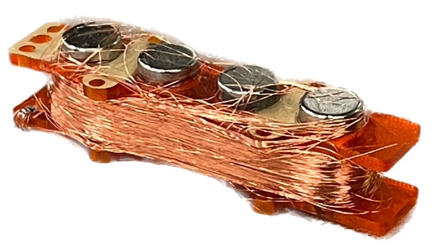 First attempt, good lord...
 Second attempt, wow...
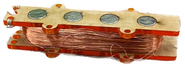
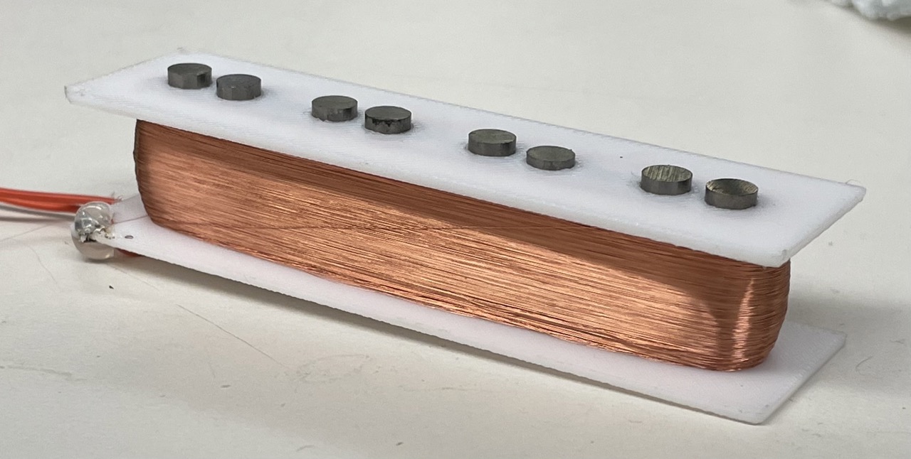
So clearly something in my process wasn't working and for finals week I went back to the drawing board. I redesigned my pickups around much thinner magnets (= more space for coils) and entirely contained in a 3D printed case.
 Two small magnets per string gives me more space without sacrificing quality
More importantly, I 3D printed a jig that contains the wire within the pickup while winding.
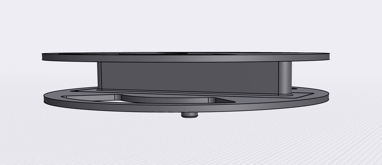 It's easy for wire to wrap outside the thing walls of the pickup...
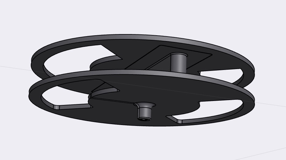 ...but there's no way it'll go around these large circles
The difference is night and day.
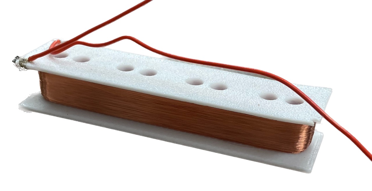 Exactly 8000 winds, and an impedance of 7.99kΩ. Nice!
 Magnets are press-fit in place using a vice
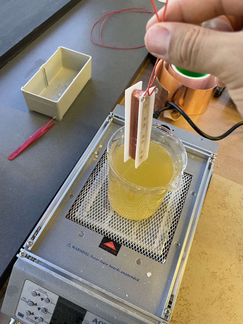
Finally, I'm potting the pickups in bee's wax; this gives a really clean tone and allows the player to crank up the volume without introducing noise.
 PLA warped slightly but the pickups' case pops it back in shape
You'd think the "hard" in "hardware" is there for a reason, and that PLA wouldn't be the right material for the job? Well, I received a brand new Bambu Lab P1S 3D printer right before starting this project and in my excitement I decided to 3D print every part.
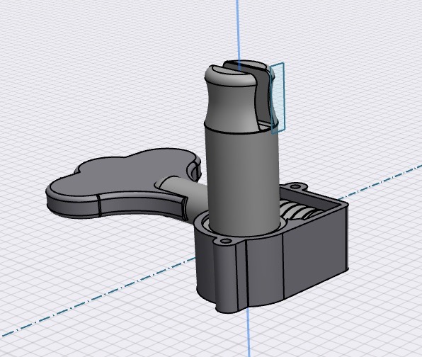 Design for the tuners; aesthetic inspired by the StingRay, mechanism by this
 I made everything in CAD first, so everything fit perfectly in real life
The bridge and tuners were my biggest concerns, though I had some success with the tuners during my initial tests so I was hopeful. Unfortunately the difference in tension between guitar strings (which worked for this guy) or a bass with really long untuned strings (which worked for me earlier) is huge, and my tuners broke all sorts of ways.
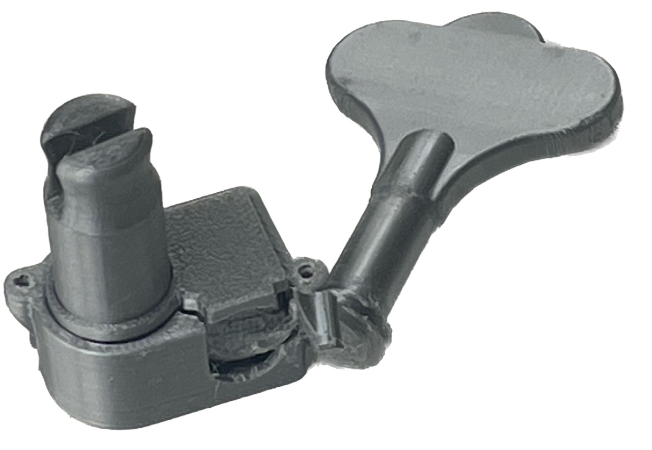 One of the ways the tuners broke
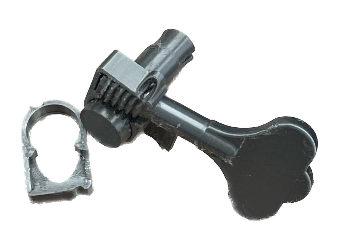 Another broken tuner
Thankfully, the string holders never sheared off or that might have been a catastrophe; usually the worm gear or knob yielded first. Nevertheless, this was some 13 hours before the deadline and I was running out of time to iterate on my design so I borrowed the tuners from a really old guitar and it worked (using some washers to account for the bass' bigger size).
As for the bridge, it seems to work fine but I didn't want to risk all four strings. For presentation day, I mounted only two strings and a wooden dowel for stress relief --- slightly unfortunate but Amazon shipping is only so fast.
Here is the guitar!
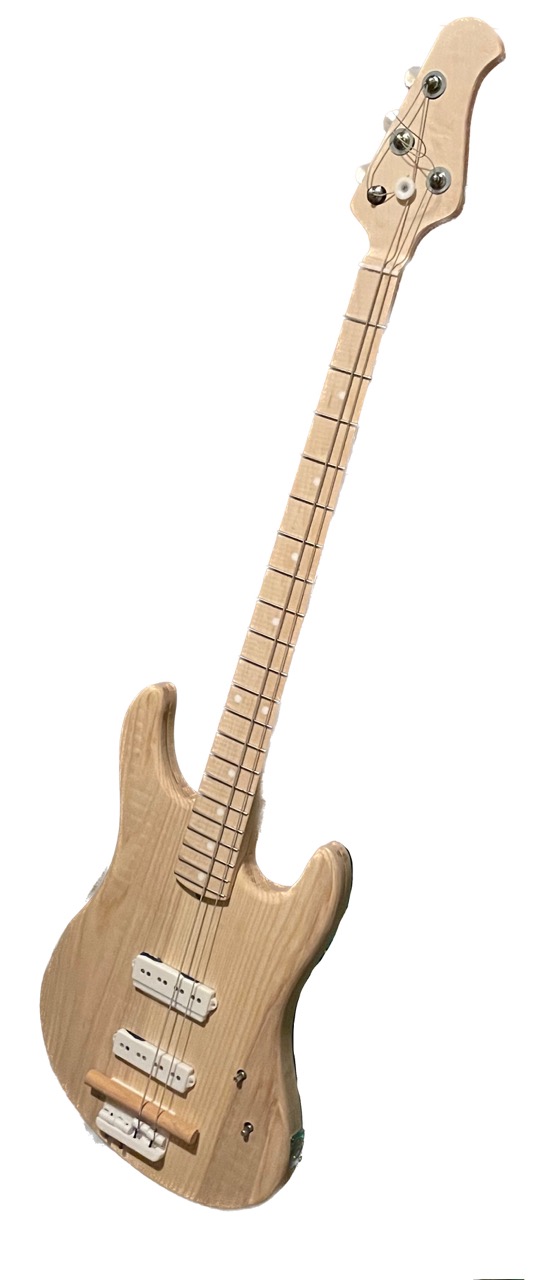
The tone is also really good. TODO(as of 21/12/23): record a video of it playing! waiting on some hardware to ship from amazon to have all four strings