
How to make (almost) everything 2023 Fall
About Me
I am Zhijian Ren, a EECS Ph.D. candidate working at Soft and Micro Robotics Laboratory. My research interest is soft actuators and micro aerial robots. This site is for class "How to make (almost) everything" in 2023 Fall and I will document all my progress here. If you need any details, do not hesitate to contact me through email.

Week 1 Laser Cut
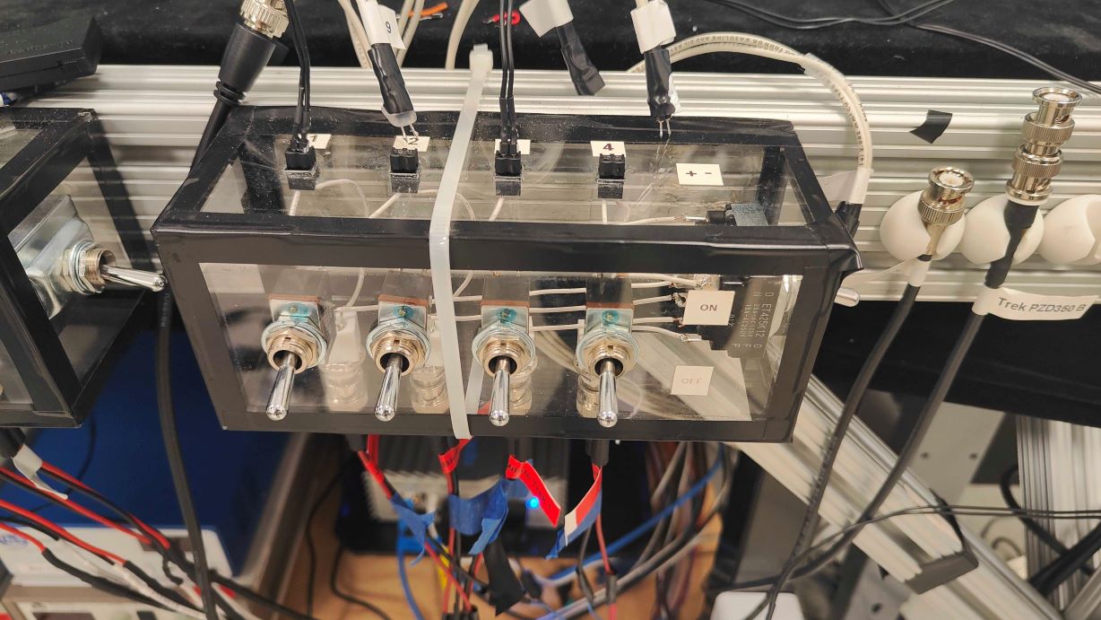
I have been using laser cutter for many research projects. For example, our micro aerial robot's carbon fiber (~160 µm thick) airframe and the safety box for our experimental setup.Carbon Fiber Airframe
Safety Box
Source Files: Dropbox
Week 2 Embedded Programming
This week is about embedded programming. I implement several scripts on the selected microprocesser (RP2040, ESP32, ...).RP2040 LED Test
The three LED lights (red, green and blue) are fading with the time. The brightness changes every one second and the whole period is 10 seconds.
Through Serial communication, I send commands to the microprocesser and the NeoPixel light will shine with corresponding color in given times.
I also manage to implement same functions in MicroPython.
The Serial communication is different with Arduino as it uses stdin to read
keyboard input and uses print to write output through the Serial COM port.
One important lesson - disconnect the Serial COM port after uploading python code and then use the Serial Monitor in Arduino (putty also works in Windows) to build Serial communication with RP2040.
In order to achieve a more accurate fading period for LEDs, I try to use Timer class and
it works well. However, it doesn't work smoothly when I combine the code with Serial communication functions.
I search online and find there are several cases that Timer will crash if there are muliple tasks running.
For example, this issue indicats that
stateMachine may be overwritten by I2S initialization. I will dig into this problem later in the semester
to see if the soft Timer in RP2040 is somewhat problematic.
Week 3 3D Printing and 3D scanning
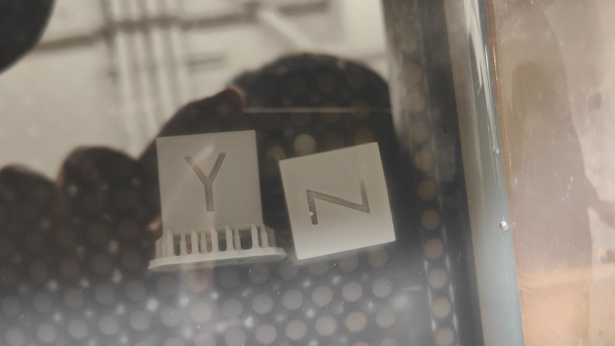
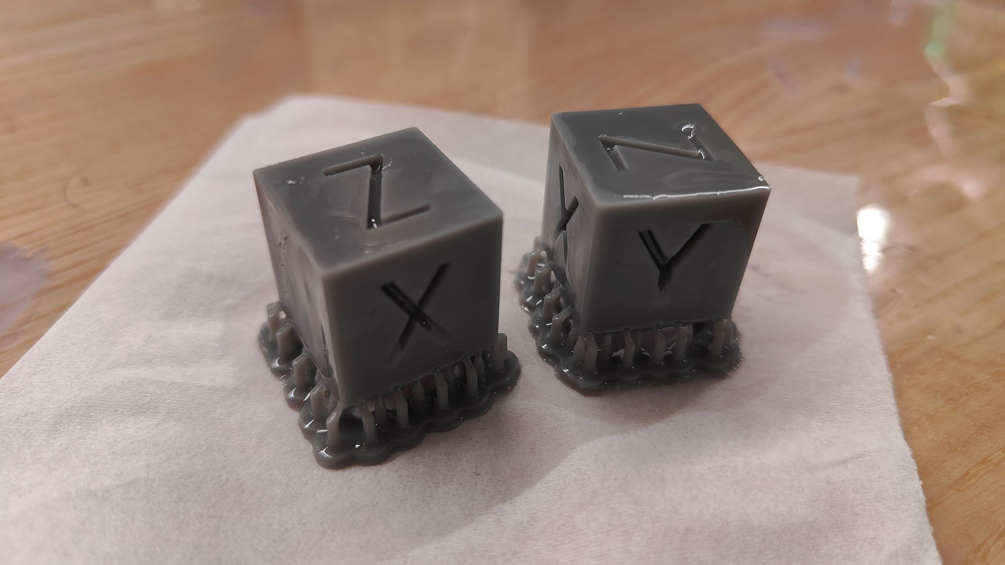
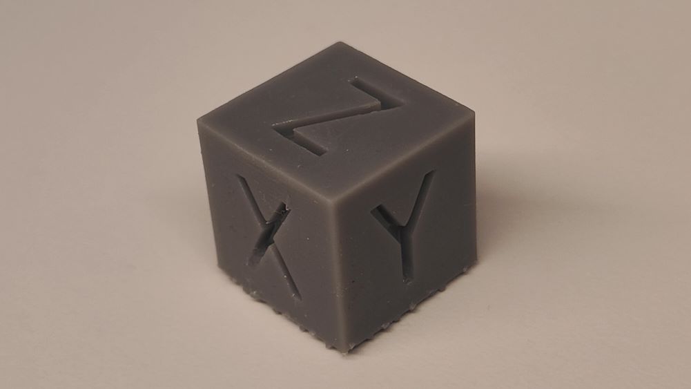
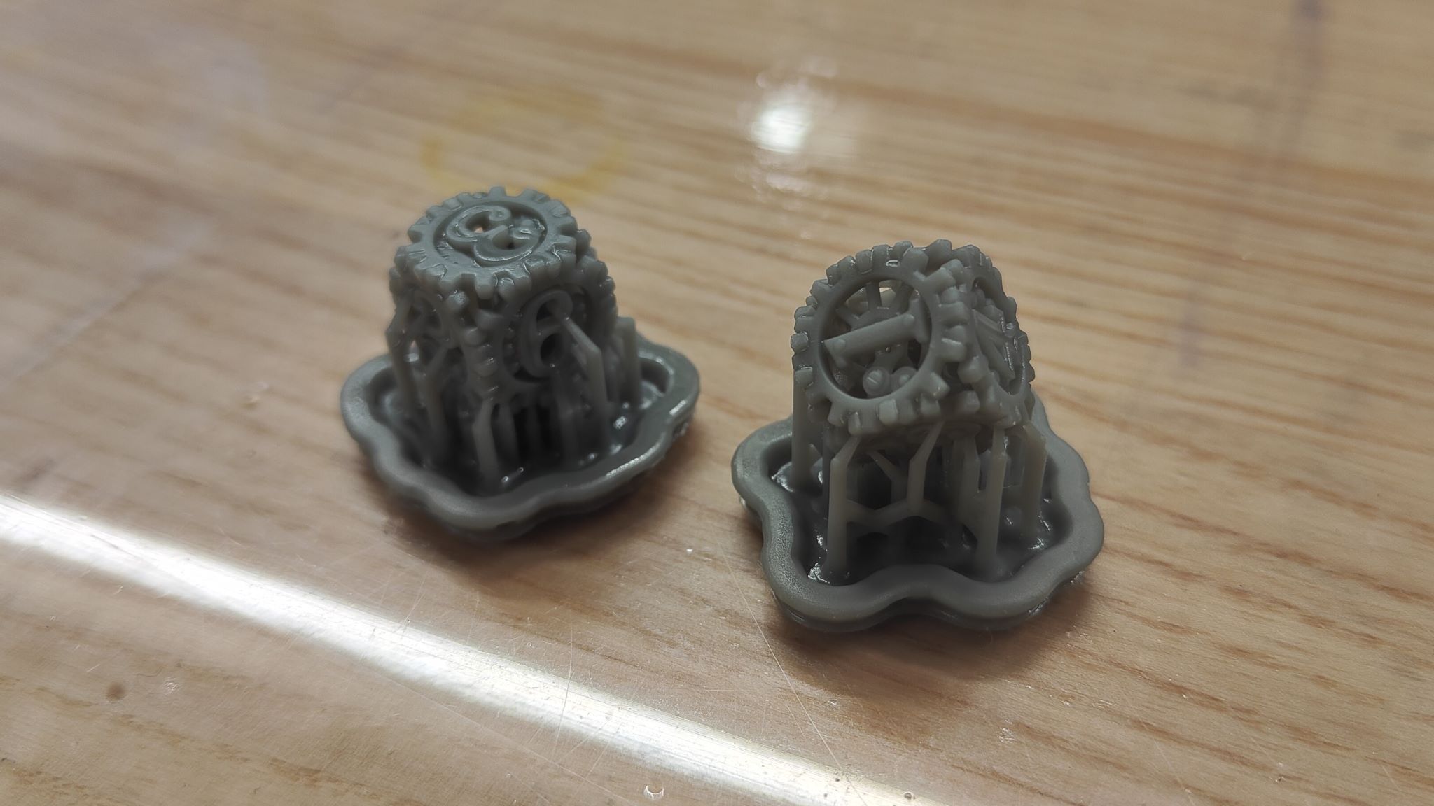
This week, I typically choose Formlab printer to make some interesting dices.Printer: Form 3+
Material: Grey
Resolution: 100 µm/25 µm
Pre-processing: design → export
→ add support → align
( Adding support and aligning parts are two necessary steps in Formlab software before printing )
Post-processing: IPA wash → Dry
→ post-cure → remove support
( IPA wash and post-cure are highly recommended in Formlab instructions )
Notes:
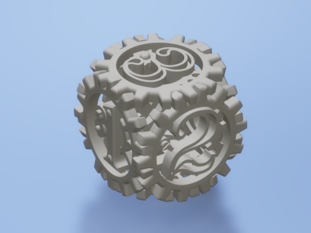
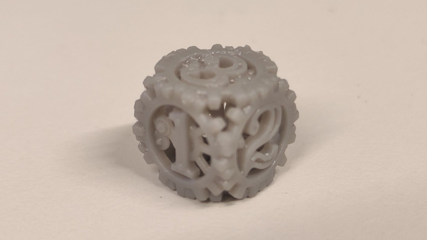
1. Steampunk dice is inspired by
Heliox's design.
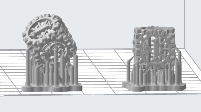
2. Internal support is required to pass Formlab's pre-check. It takes several iterations to find an adequate support that balances between how stable the
printed part will be and how easy to remove the support.
3. 25 µm resolution takes four times longer to print than 100 µm. However, the printing performance is not that different. So it is worthwhile to have
a fast prototype first and do all the necessary modifications then have a fine resolution print.
4. STL files can be found
here.
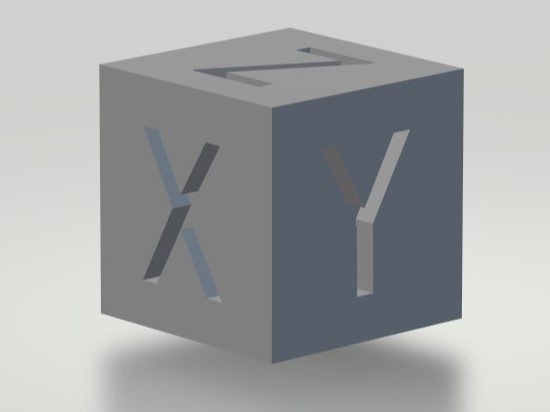
XYZ Dice
Steampunk Dice
3D scan
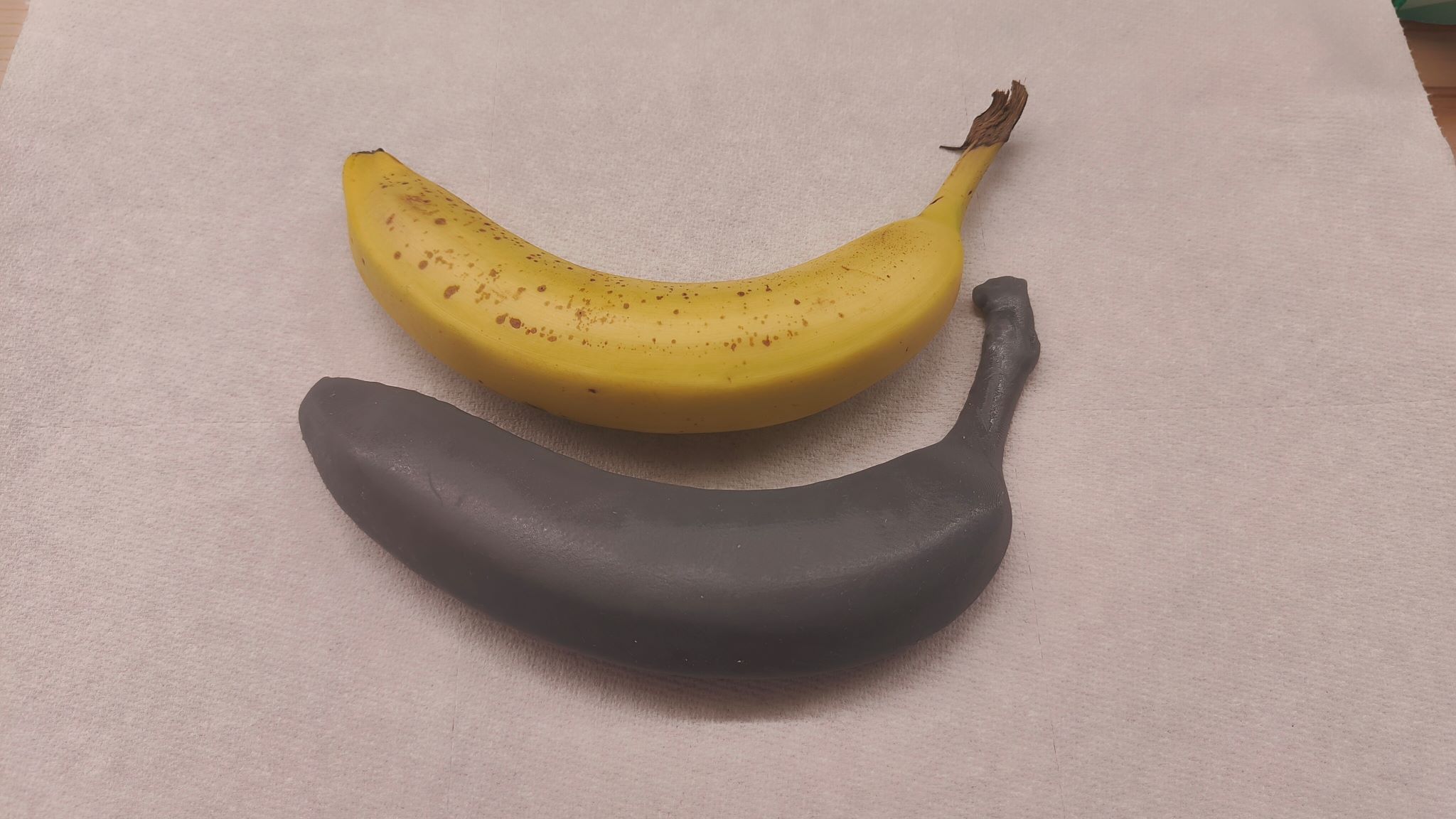
The 3D scanner I use is Revopoint POP 2 from EECS workspace and it cannot caputre tiny features or small objects. Therefore, I cannot use it to scan my dice (very unfortunately). Instead, I scan a banana and use spray pen to have the scanned model yellowish, more like a banana.
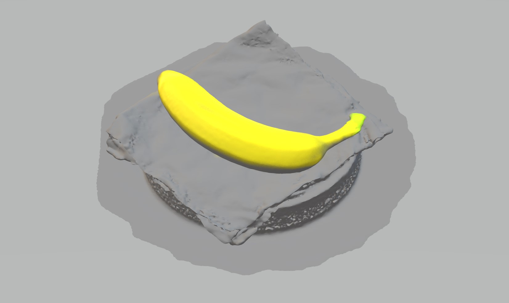
After that, I use 3D builder to split the model and the single banana model is ready to print.

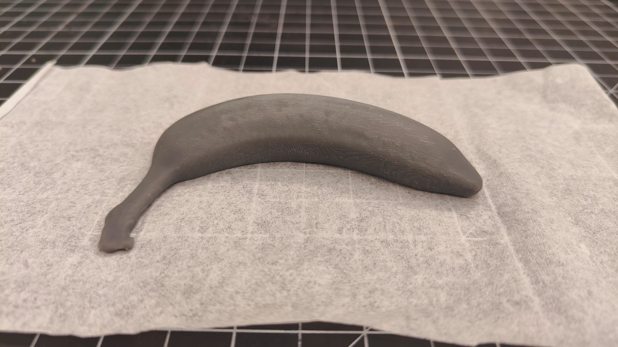
I have initially managed to print a 1:2 size banana and then have the printer working for 8 hours at night to print a whole size banana. Since the 3d scan model does not capture every details and fail to scan the bottom surface, the printed banana is not exactly similar to a real one.
Week 4 Electronics Design
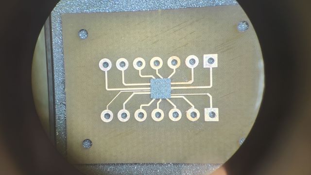
This week, I have designed a evaluation board for a tiny package MCU Attiny84A-CCU which was used in my previous research. It is a 8-Bit, 20 Mhz microcontroller with a Ultra Fine-pitch Ball Grid Array (UFBGA) packaging. Its size is 3mm x 3mm and only weighs 8 mg. It has 12 programmable I/O lines that is enough for most applications.Altium Designer is the software for my design and file export to fabricate.
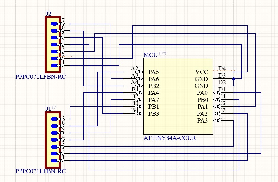
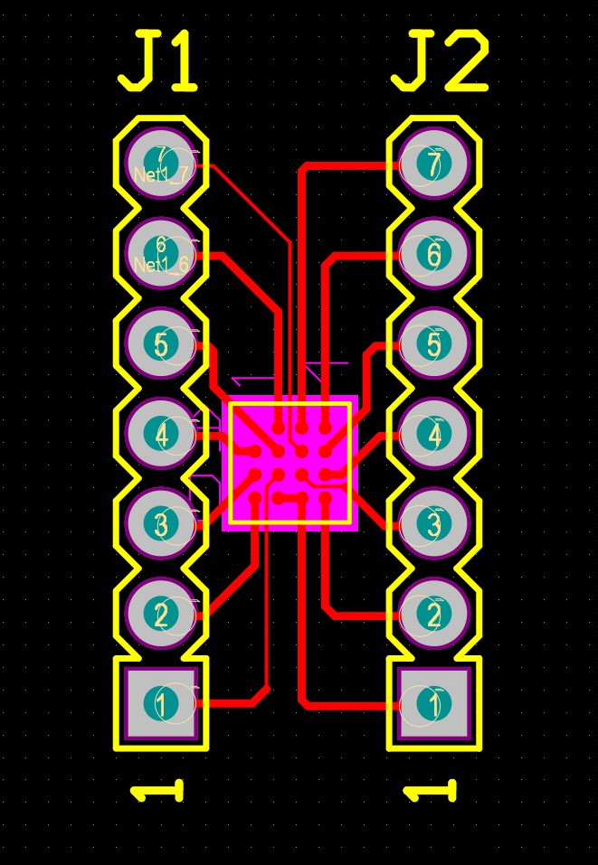
Since I want to fabricate the evaluation board with our own LPKF laser cutter, I have several traces shrinking down to 5mil width.
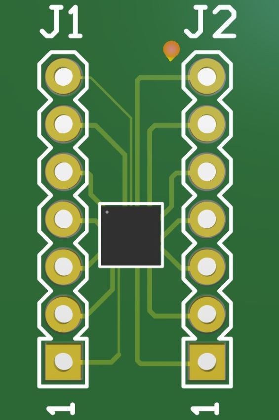
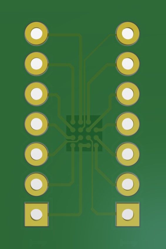
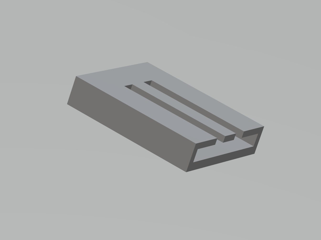
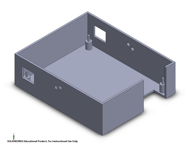
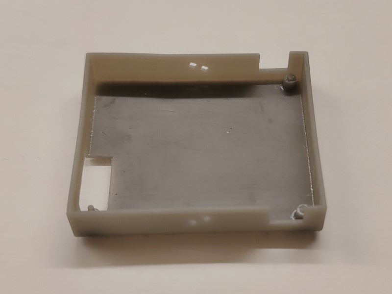
I also design a case for the evaluation board, which I will 3D print in the next week.
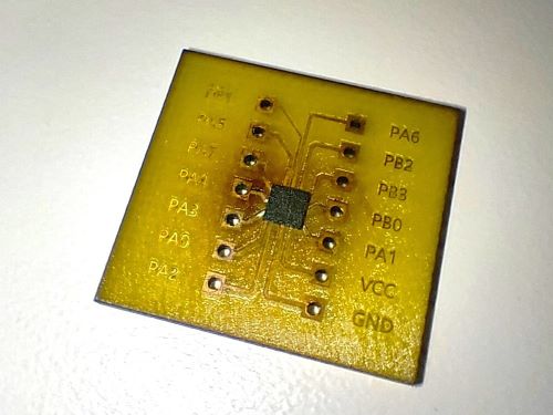
Week 5 Electronics Fabrication
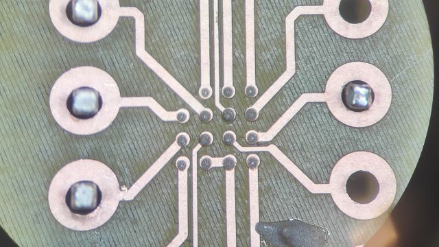
This week, I fabricate the evaluation board designed last week, fine solder the components onto the board and 3D print a case for protecting the board.Board Fabrication
The LPKF ProtoLaser U4 is able to structure, engrave and cut materials in a single operation. The laser focus with a diameter of about 20 µm allows for structures with a pitch of 65 µm (50 µm line width, 15 µm apart) related to FR4 with 18 µm Cu.The whole fabrication process only takes a few minutes and all traces are clear and isolated.
Component Soldering
There are several steps for a fine soldering of a bga package:1. Put a mask on the layout of the component.
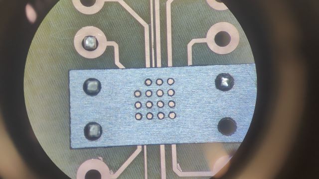
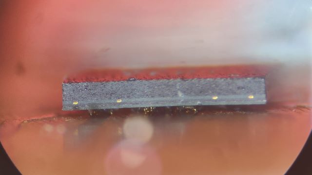
2. Put adequate solder paste on the layout. Gently swipe away the extra paste. Take the mask off.
If everything works well, it can be seen under the microscope that the soldering ball is "floating" on the pad.
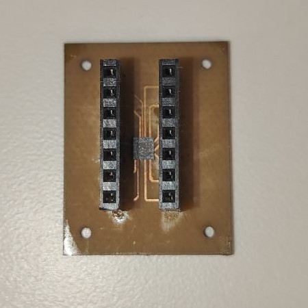
The functionality of the evaluation board has been verified by following this tutorial. The basic idea is to program the Arduino to use as an In-System Programmer (ISP) and then connect the evaluation board to the Arduino for programming.
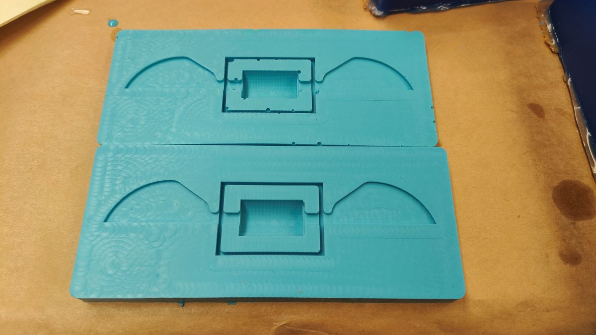
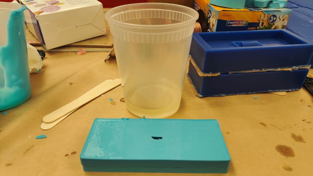
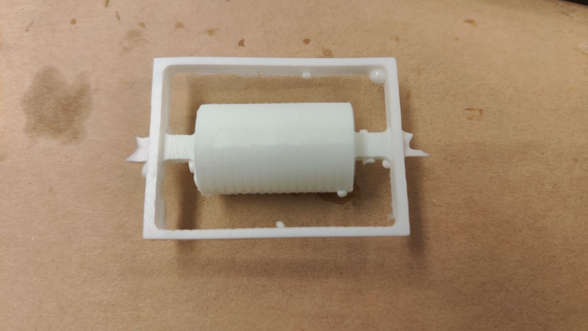
Week 6 Casting and molding
This week, I cast and mold our lab's logo - an insect inspired robot.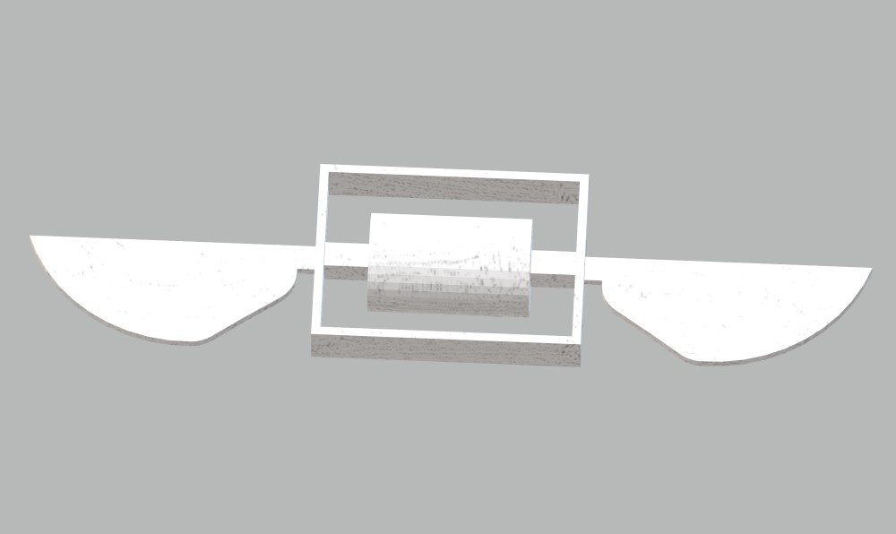
Then, I split the design into half and embed into a 3"x7"x1.5" box.
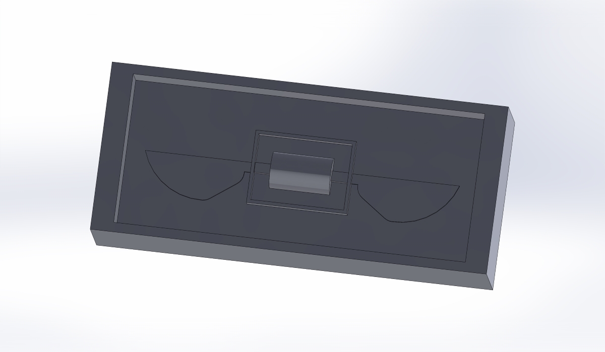
I exported SolidWorks design into STEP file and Anthony helped me imported into Fusion to check and generate the G-code. The CAM tool indicates some tiny features are not able to drill (using 1/4" and 1/8" endmill). So I increase the thickness of the wings and increase the gap between the wings and the center body.
Now it is time to use CNC machine: 1. Use hotgun to fix the position of the wax box. 2. Install 1/4" endmill by using two wrenches. 3. Calibrate X, Y and Z offset with a precise sensor (I didn't write down the name). 4. Clamp on some protection cover to prevent the drilled material flying everywhere. 5. Check vacuum and then start drilling. 6. (Optional) Increase feed speed to save time. 7. After stop, remove the protection cover and switch to 1/8" endmill. 8. Calibrate Z offset and clamp on protection cover. 9. Continue with drilling. 10. Use vacuum to remove all the drilled material after it is done.
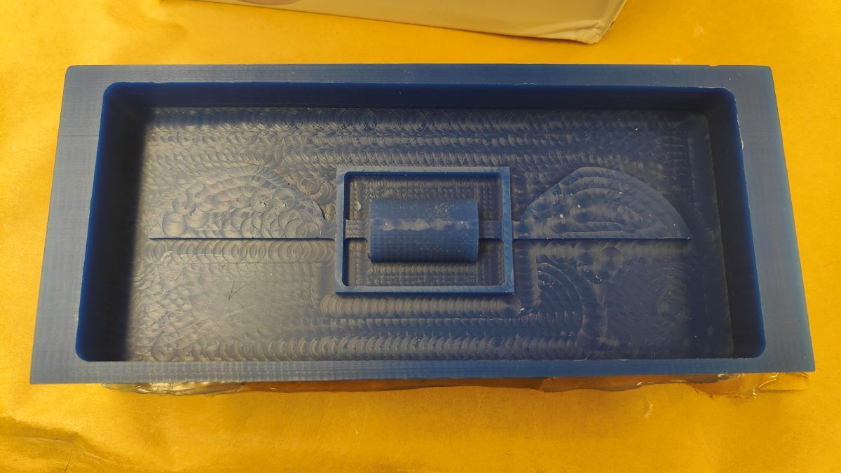
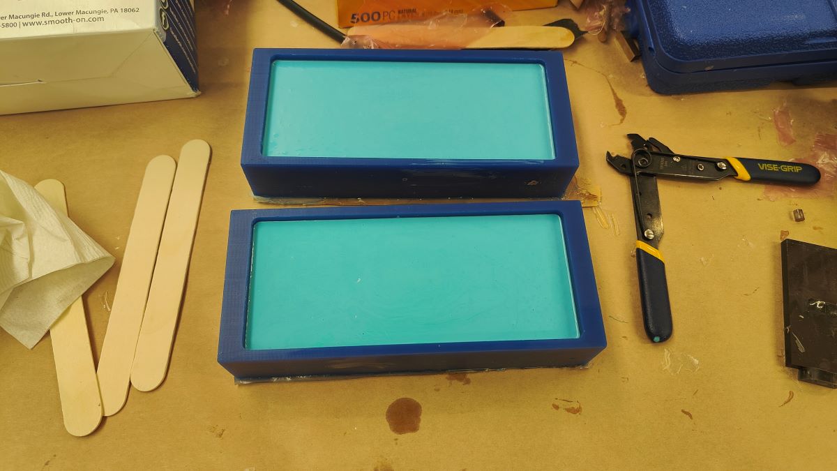
After waiting for two hours, I manage to take the oomoo mold out.
Week 7 Computer-controlled machining
I was out for a conference so I will probably make it after coming back.
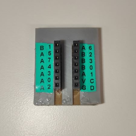
Week 8 Input Device
This week, I worked on a powerful 9-DOF IMU ICM20948 that will be potential used in my project.I started with I2C communication to have the MCU talk with ICM20948 and then tried SPI as well. Thanks to the libraries provided by SparkFun and Adafruit, I managed to get the raw measuremnts very smoothly. With a low-pass filter to eliminate some noise, I can easily detect motion in a 3D space.
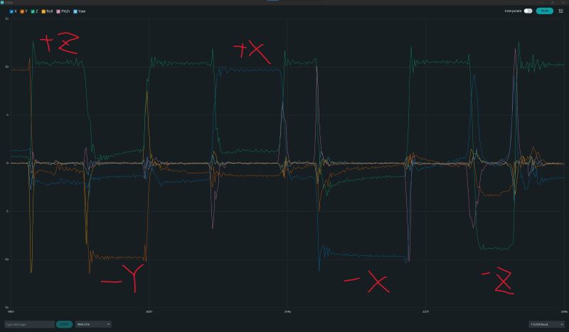
I also played with the operating frequency of the accelerometer and gyroscope to see if I can get a relatively smooth raw data. The result indicats a sad "NO" so I choose to write some motion processing algorithm to get the position (x-y-z) and rotation (roll-pitch-yaw).
Thanks to ZaneL's library, I managed to test the DMP function with a Teensy 4.1 board. In order to analyze the accuracy and test the controller (for the project in the future), I wrote a script in MATLAB to animate the trajectory.
Week 9 Output Device
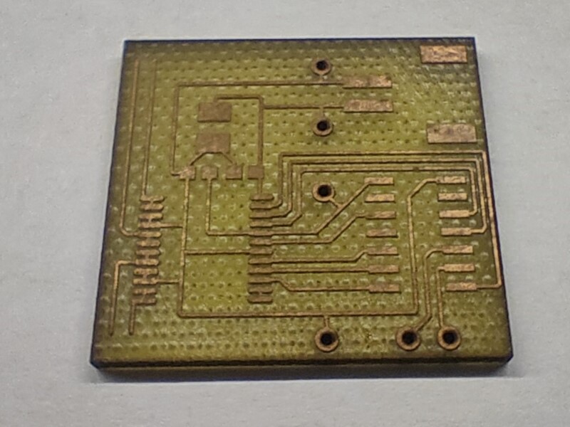
This week, I designed a PCB that combines an Attiny84a microprocessor and a TB6612FNG motor driver to control the spinning of two motors. This is also a preliminary design for the project.Design
The design process has been gone through several iterations and some functions will be used in the project. The whole PCB requires 4 inputs to build Serial communication with another Arduino (5V, RX, TX and Ground). After intepreting the instruction from Serial Input, the microprocessor will program the motor driver to control the PWM voltage of two channels separately. A 400mAh LiPo battery is used to power the motor. In the next iteration, a regulator will be included to convert the battery voltage to 5V that can power the MCU as well.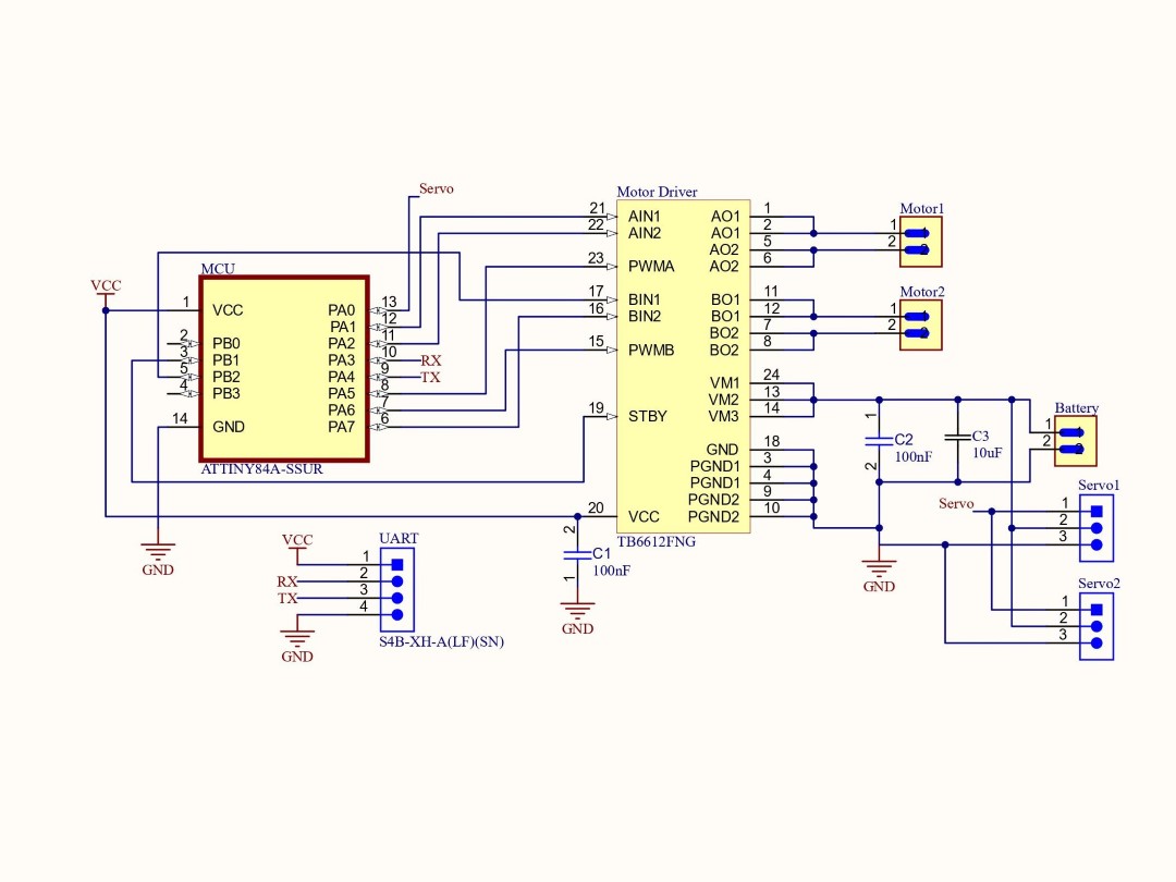
After laser cut
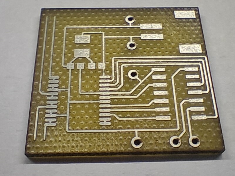
After tinning
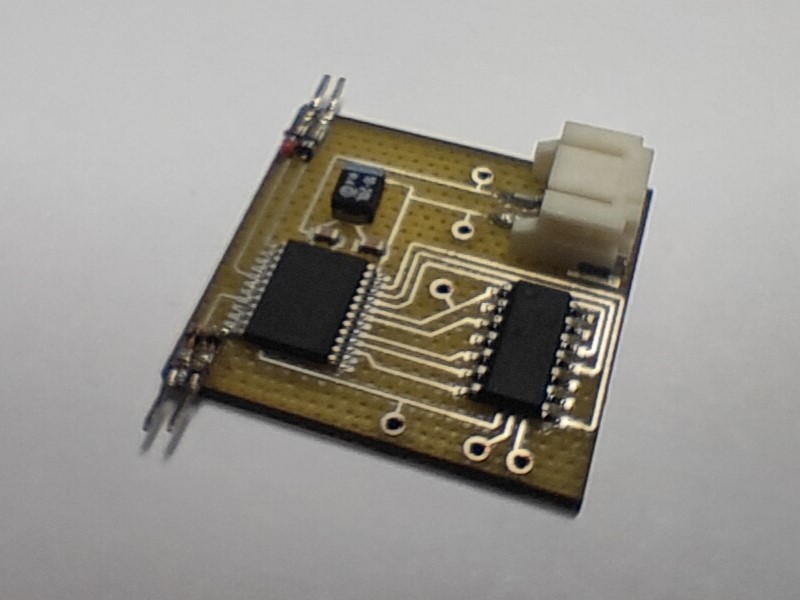
After components soldered
Week 10 Networking and Communications
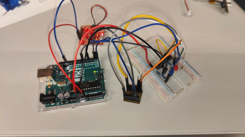
This week, I programmed an Arduino Uno and an Attiny84a to communicatie with each other through UART.Goal
Each MCU has one digital input to detect whether a switch is pressed and one digital output to turn on a LED. The UART communication between the Arduino and Attiny84a is able to have each MCU tell the other one whether its own switch has been pressed or not. So basically one side's switch controls the other side's LED in an indirect way. A 3.7 V LiPo battery is used to power both MCUs for proving there is no communication through the computer.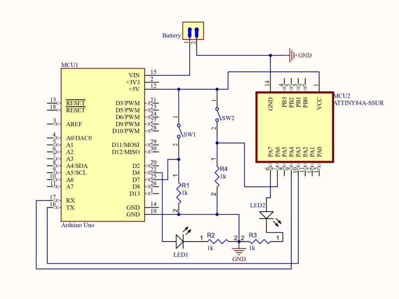
Week 11 Interface and Application Programming
Week 12 Mechanical Design
Unfortunately I was sick this week and only contributed to some documentation.Week 13 Wildcard week - Laser induced graphene (LIG)
This week, I learn from Wedyan how to use laser to decomposite Kapton into a graphitic substance. My plan was to use LIG as soft electrode to fabricate dielectric elastomer actuator (DEA).However, I have a lot of trouble on transferring the LIG onto the elastomer. It seems that only the LIG made from the laser in Mars can be transferred onto a certain elastomer (Sylgard 184).
I am quite frustrated about this situation and try to find out the reason. Here are the few samples that I have tried (I was hoping to transfer so I didn't take photos for most failing ones).
LIG made by EECS laser and transferred sample onto our lab's elastomer (P7670).
It can be seen and measured by multimeter that almost no graphene has been transferred onto the elastomer.
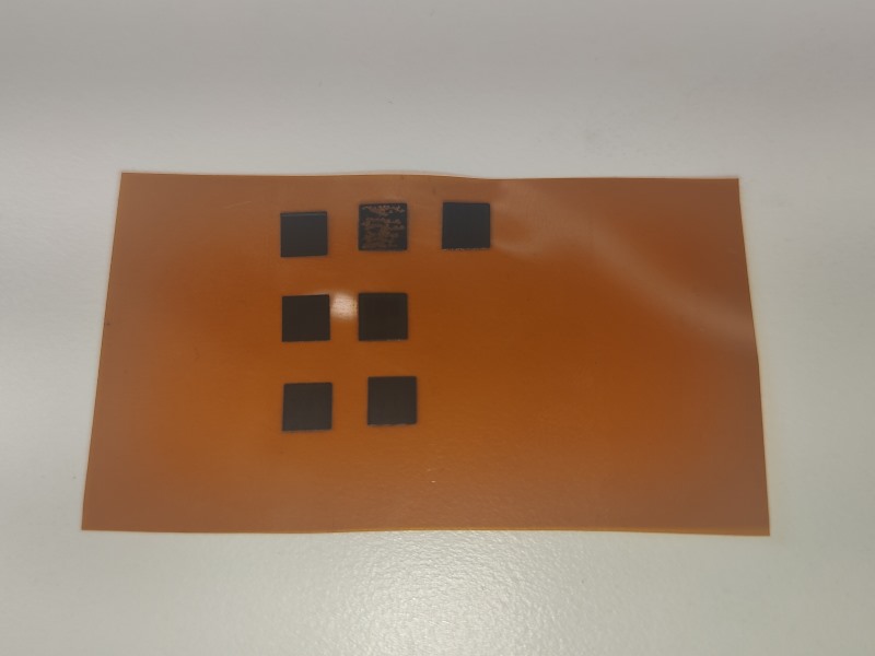
LIG made by Mars laser and transferred sample onto P7670.
I tried two curing approach - left: half cure elastomer first then stamp the LIG onto it; right: pour uncured elastomer onto the LIG and peel the Kapton after fully cured. Neither of them works properly but I find some graphene has been transferred onto the elastomer in the left sample. And locally the multimeter has some readings on resistance.
Project
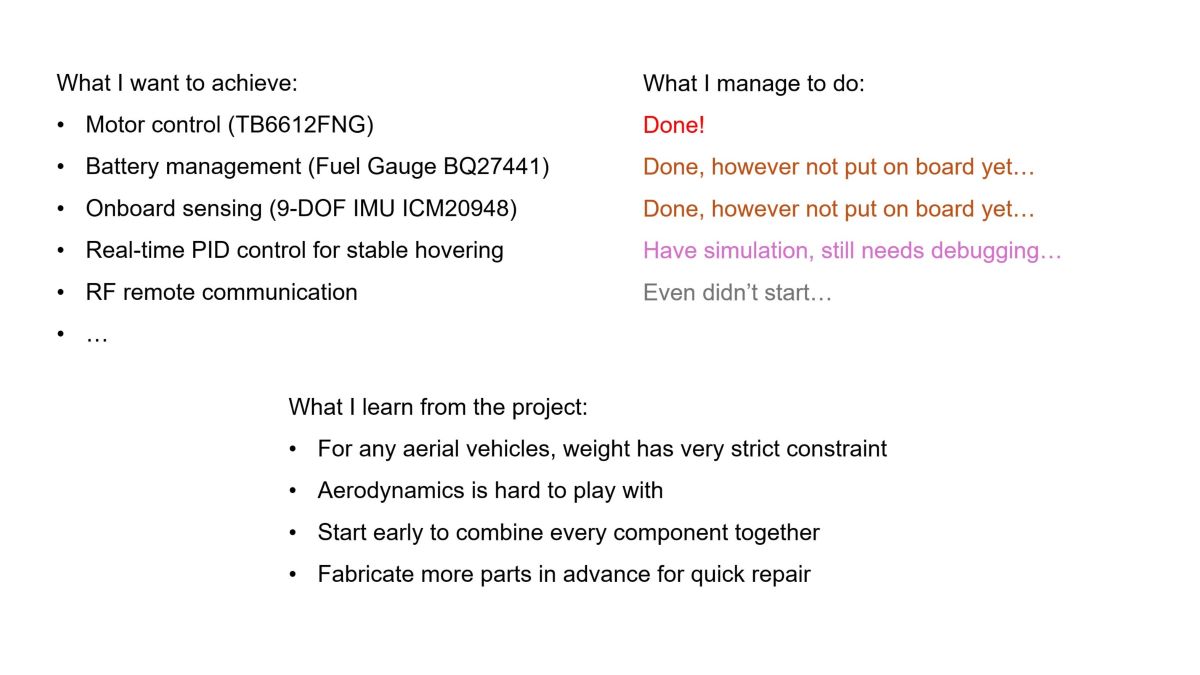
What I want to make?
Since I have been working with aerial robots for a long time, I am quite interested in some new designs of flyer. One of them is a revolving structure, not like the helicopter's rotorhead, but instead having motors and small propellers on the tip of the wings. The YouTube videos on the right side inspires me to make something that is able to fly in a different way other than drones or fixed-wing planes.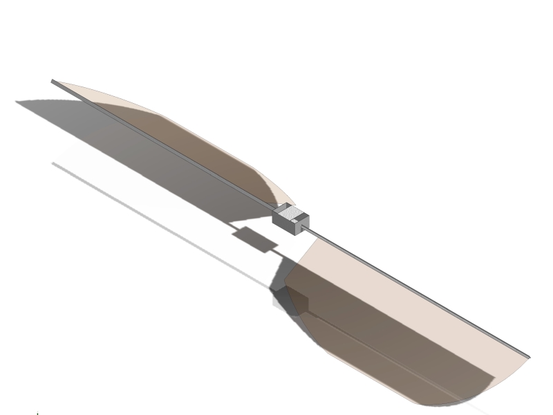
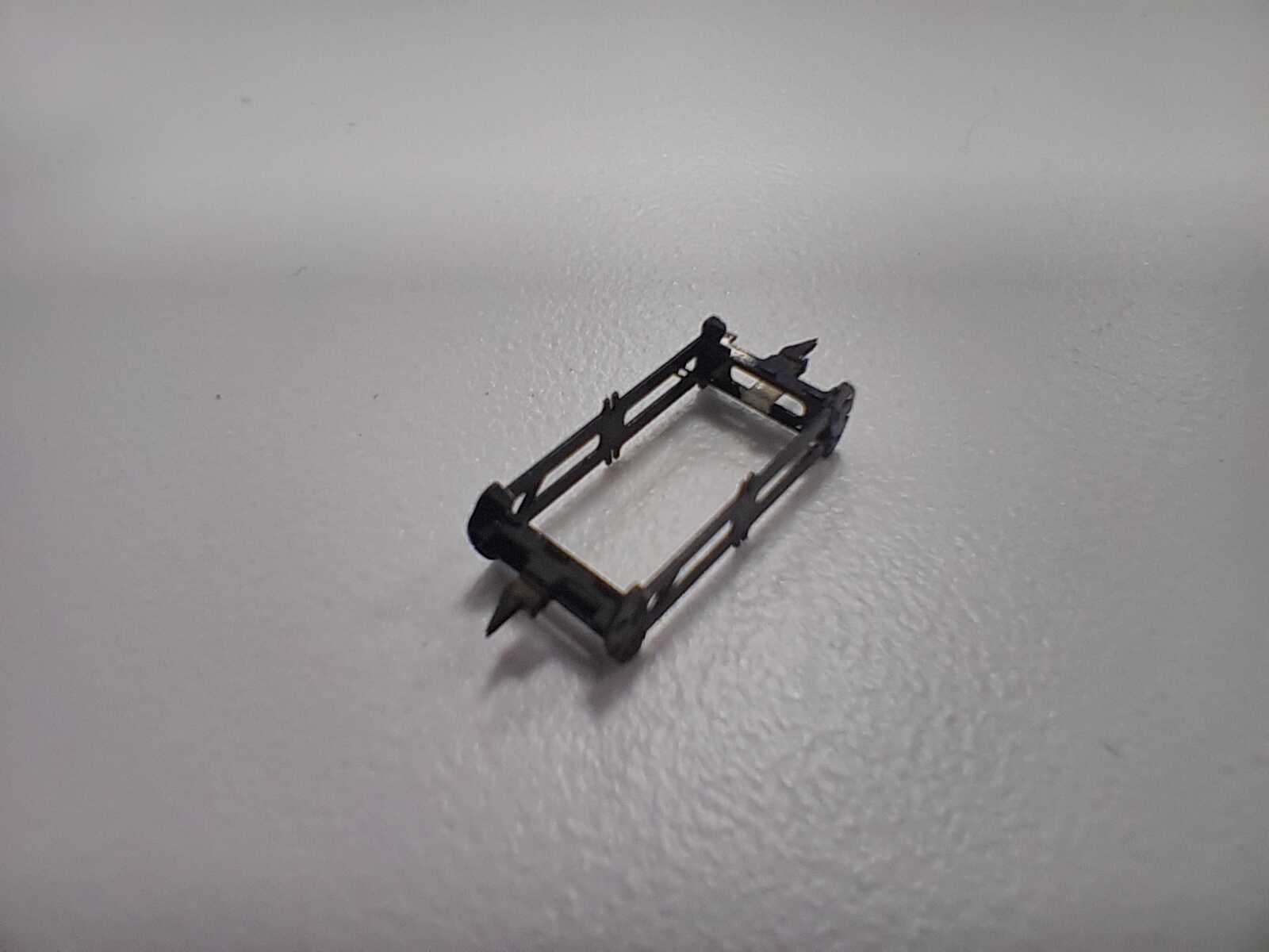
Platform design
For preliminary test, I design a pair of wings and a center mounting structure for revolving. In order to reduce weight, it would be good to use thin and stiff material like carbon fiber. However, after considering the cost, I choose to use FR4 as the base material. The thickness is calculated to be stiff enough to hold the motor at the tip while not inducing bending (less than 3 degree). Usually I use 1/32" thick FR4 as airframe and mounting structure and 50 μm thick Kapton as airfoil. All the material are designed in QCAD and cut by the laser cutter. Laser parameters are tunned so that no burning marks are visible and the mounting is strong even without glue (I reinforce with glue still when doing the revolving test).
Some of the revolving tests indicate that the design is good enough (not optimal) to generate lift force larger than its own weight. It is promising to have something taking off without control.
Circuit design
The first implementation is that the circuit includes a MCU, a motor driver and some capacitors to stable the voltage. As shown in Week 9, the chosen MCU - Attiny84a and motor driver - TB6612FNG functions well on a customized PCB. The motor speed can be controlled by the input instructions through Serial communication.(!Note: I modify the Arduino library for TB6612FNG to have easier coding on motor control.)
Next, considering there are still some MCU's pins left unused, it would be good to have two servos that control the wings' pitch angles while revolving. This adjustment doesn't need to achieve fast response so I believe some small servos can be used here. (The revolving design doesn't need to change much so it is also easier to throw away servos if the weight is a hard constraint.)
Schematic
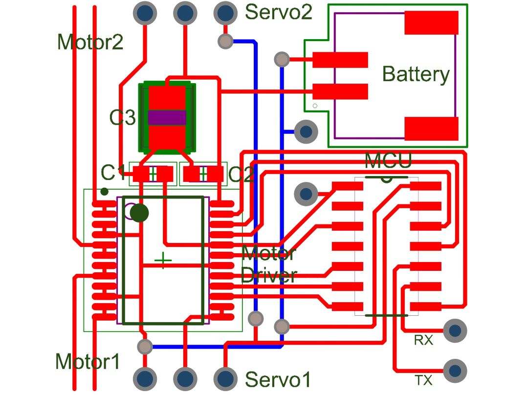
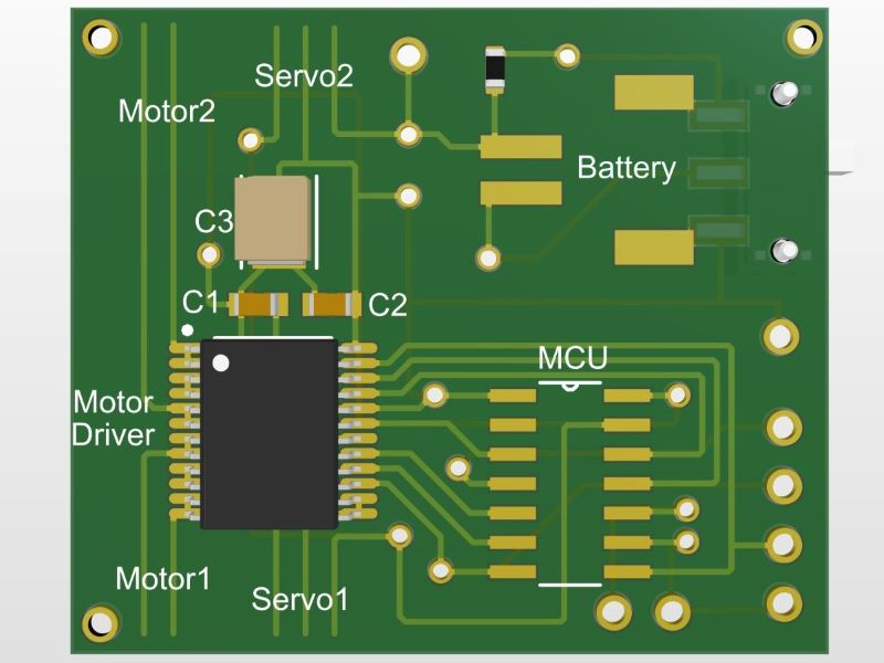
Board Design
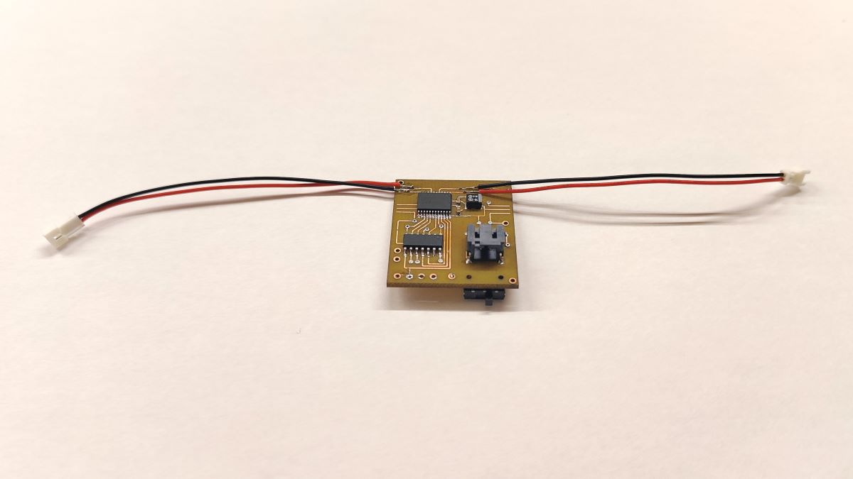
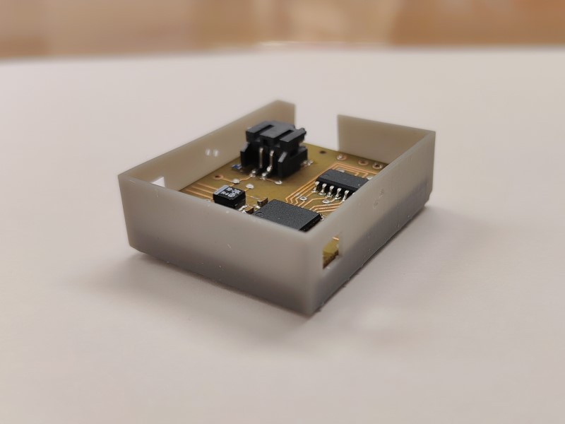
Functional PCB
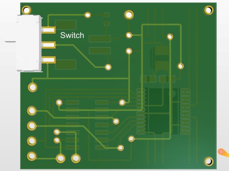
There are a few iterations back and forth, such as adding LEDs to indicate the status of motor, adding a switch to turn on and off the battery and even something like adding a few pads for easier uploading and debugging. The final version is shown below (the reason to throw away the servo is that it adds more weight to ensure the wing's mounting and that some vibrations occur when revolving).
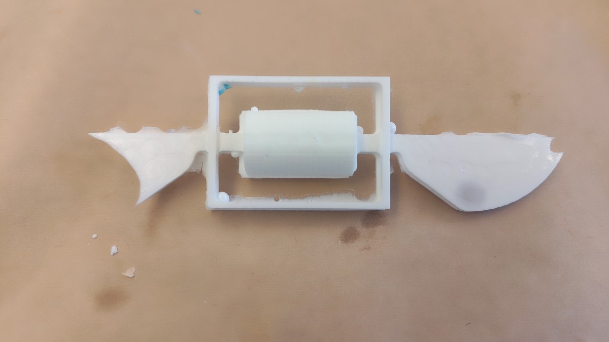
3D Printed Case
The 3D printed case is designed for containing the PCB and having battery attached as well as leaving space for switching the battery's power. Additionally, both wings are supposed to be mounted on the case with a desired pitch angle.Many iterations have been gone through to adjust the PCB and the location of switch. The thickness of the case is also minimized to reduce the weight while can still provide strong support for the wings.
Finally!
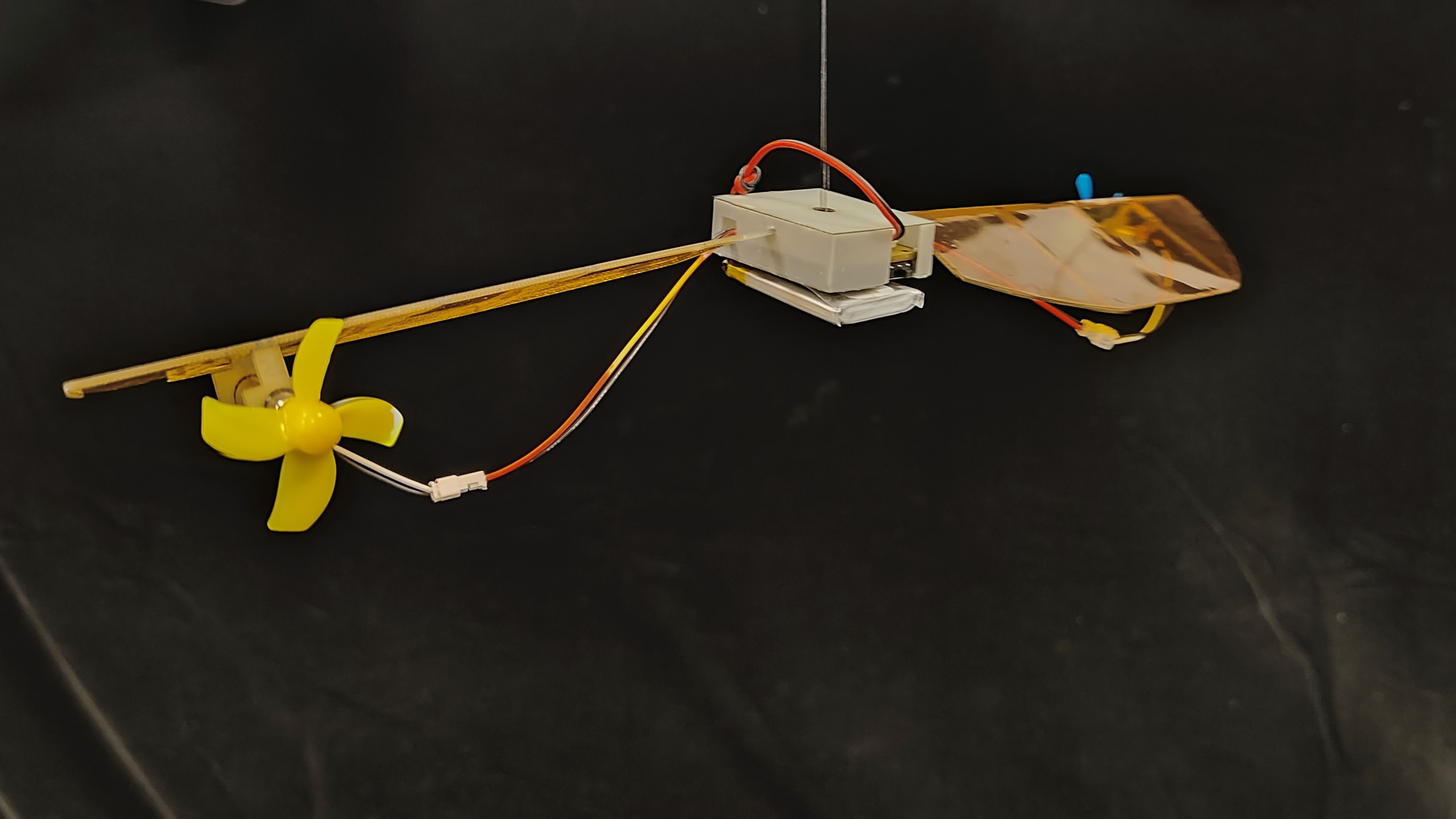
And...
Source Files:Dropbox