DAVID A. MELLIS
MAS.863: How To Make (Almost) Anything
Week 7: Input
Capacitance meter
I started with the idea of making a small flute-like musical instrument with a microphone, button pads, and a speaker. This proved difficult to route, so I cut back to a four-pad step response board (Eagle files: buttons.brd, buttons.sch). This made it less interesting, so I didn't do much with it.

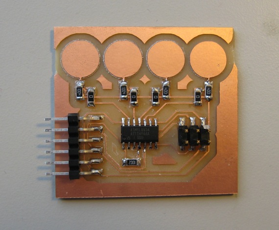
See some stray, unmarked capacitors in 016 inspired me to make a capacitance sensing board (Eagle files: capmeter.brd, capmeter.sch). The C1 footprint is left unpopulated, so you can place a capacitor on it to measure. This board is based on the hello.step.45.cad board, but modified to use a 6-pin header that mates with an FTDI cable. To ensure enough space for a 1/64" endmill between the diagonal traces, I set the wire-wire, wire-pad, and pad-pad clearances to 20 mil (in Edit > Design Rules).
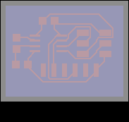


Exporting PNGs from Eagle to load into cad.py. The rectangle on the bottom layer can be used to contour the outside of the board. The larger gray one (on the document layer) ensures there is enough margin around the bottom rectangle for the toolpath to fit inside of.
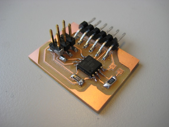
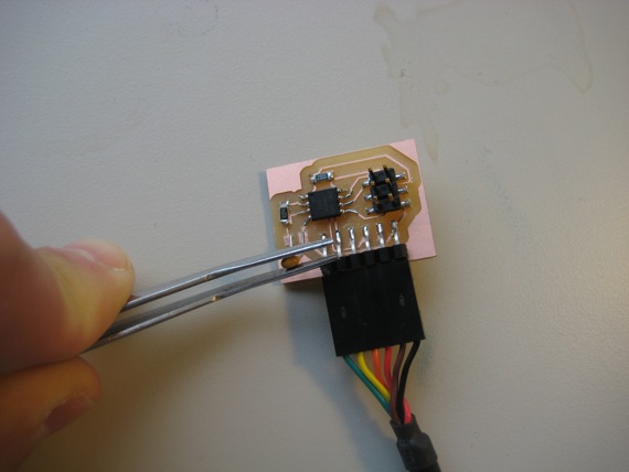
The assembled board. I marked pin one of the ISP header with a metallic silver marker.
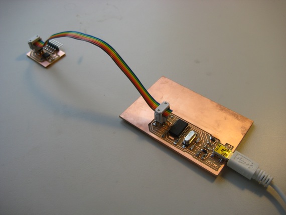
Programming the board with my homemade FabISP programmer (based on the USBtinyISP). The FabISP supplies power (regulated 5V from the USB connection) to the target board.
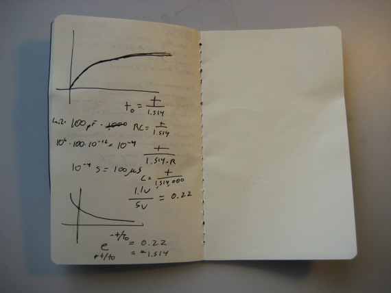
Here are my calculations for converting time to capacitance. David Carr reminded me of the importance of choosing an appropriate resistor for the capacitance range I wanted to measure - to ensure a reasonable time constant. I went with a 1M ohm resistor to be able to measure picofarad capacitors.
Measuring a capacitor. It can be difficult to keep in place, but if you're patient, you'll get a value.
My program (hello.step.45.asm) uses the comparator. First, it charges the capacitor. Then, as the capacitor discharges it measures the time it takes for the voltage to drop below the comparator reference. The two byte time value is sent over the serial port.
Here's the code for initializing the comparator:
   sbi ACSR, ACBG ; use 1.1V reference
   sbi ADCSRB, ACME ; enable mux input
   sbi ADMUX, MUX1 ; select ADC2 (PB4)
   cbi ADMUX, MUX0 ; "
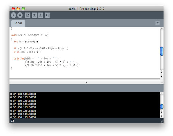
The Processing program that reads the time data from the serial port and converts it to a capacitance value (capmeter.pde). The formula is relatively simple. I combine the two bytes, subtract the value when no capacitor is present, and multiply by the number of clock cycles per measurement loop to get the number of microseconds for the voltage to drop below 1.1V. Then, I divide by 1.514 (computed from the capacitor discharge formula) to get the capacitance in picofarads. For the picofarad range, this is relatively accurate. When I tried a 68 pF capacitor, I got a reading of 69 pF; a 100 pF capacitor gave 105 pF.
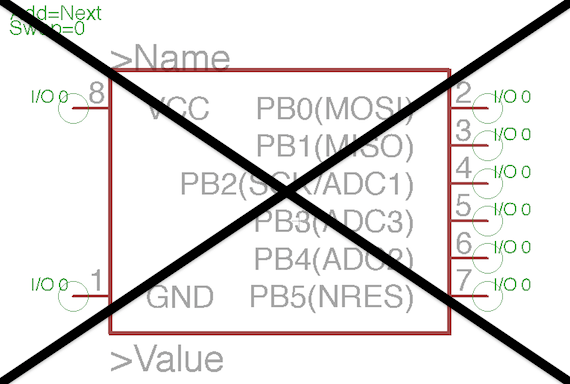
Finally, a warning: check your footprints. I initially used the ATtiny45 device from the SparkFun Eagle library, but it had the wrong mapping between pins and pads.