contact // irina chernyakova
1 [0912] FINAL PROJECT PROPOSAL 2 [0919] COMPUTER CONTROLLED CUTTING 3 [0926] ELECTRONICS PRODUCTION 4 [1003] COMPUTER CONTROLLED MACHINING 5 [1010] FINAL PROJECT UPDATE 6 [1017] MOLDING / CASTING / COMPOSITES 7 [1024] EMBEDDED PROGRAMMING 8 [1031] 3D SCANNING + PRINTING 9 [1107] INPUT DEVICES 10[1114] INTERFACE + APPLICATION PROGRAMMING 11[1121] OUTPUT DEVICES 12[1128] MECHANICAL + MACHINE DESIGN 13[1205] NETWORKING + COMMUNICATIONS 14[1212] FINAL PROJECT DEVELOPMENT 15[1219] FINAL PRESENTATIONS
1 fabISP programmer
This week we made the fabISP in-system programmer. We will be using it to program the microcontrollers on other boards that we will make throughout the semester. We were provided with the board design, trace files, and board components – thus no design just yet. The sections this week covered milling the board using the Roland Modela milling machine and “stuffing” the board – soldering all the necessary components onto the board.
2 milling [roland modela]
The fablab archive has some great archive resources for using the machine, canceling jobs. I read over this page on milling the board through fab modules before section – highly recommended.
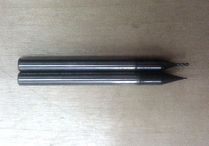
end mills:
top, 1/32” coated end mill / used to cut border; bottom, 1/64” coated end mill / used to cut traces
Be very careful when removing and changing the bits. Hold the bit with your fingers to prevent it from falling and breaking. When prepping the bit to mill, bring it down using the up/down buttons, hold & unscrew. When tightening, hold the bit and push it down against the material since tightening pulls the bit up.
Notes on milling:
Make sure there is a sacrificial board already on the bed.
Use double-stick to secure your board onto this board. Align, and press down to level the surface as much as possible.
Set (x,y) to (0,0) on your board. On the fabmodule – in the third module, you can set the (x,y) coordinates for your board. Use the grid on the bed to measure & approximate location.
Use the View button to move the bit to (0,0).
The machine remembers the coordinates of previous cuts – in order to reset the machine, turn it off & on again.
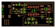
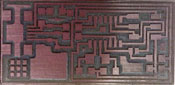
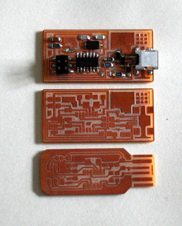
This is the trace file.
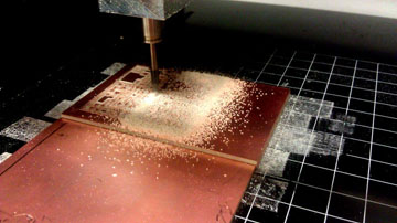
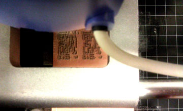
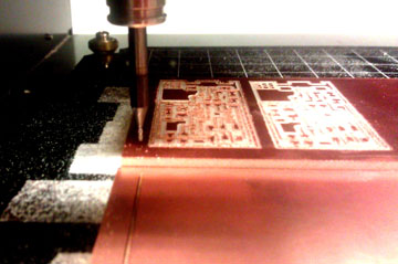 [milling]
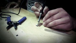
3 stuffing / Carolina's soldering + stuffing page, helpful to those with no knowledge of electronics.
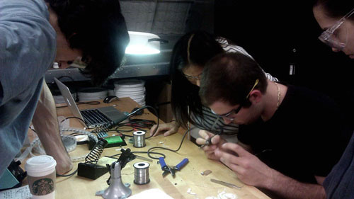
This is the schematic drawing provided. Compare the drawing to the milled board below!
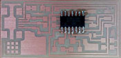
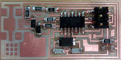
The clean milled board: use a soft sanding sponge to clean off any edge residue from milling. Sand in a single direction!
Start soldering the interior components, and work your way out. This is the A44 microcontroller. This is a directional component – if you look closely, a small circle indicates the position of pin 1. The board trace has a circular end. Match the small circle to the circular end.
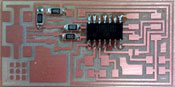
Resistors, can be soldered in any direction – make sure you pick the correct measurement! Resistors are measured in Ohms – the ones above are 1K ohms, 10K ohms, and 499K ohms. These limit the amount of electricity flowing through the circuit.
Diodes, have a directionality – from A>C, anode to cathode. If you look closely, there is a line etched into the component that marks the cathode side. Diodes allow the current to flow in the opposite direction if it goes beyond a certain voltage.
Capacitors, are non-directional, and are measured in Farads (uF/nF/pF).
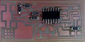
Resonator, 20 MHz; non-directional, used as a sensor to track frequency (?)
ISP, connection point to other board/programmer
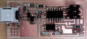
USB connection, probably the most difficult to solder. Solder the four legs first, then very carefully, with minimal solder, solder the traces.
Program, and de-solder. This is Carolina's video of how to use a copper braid to de-solder.
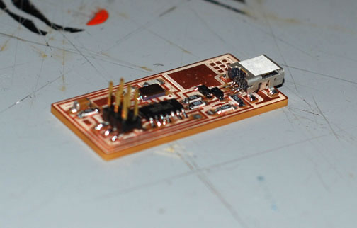
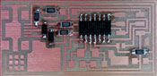
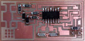
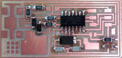
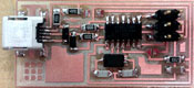
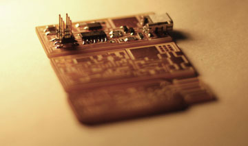
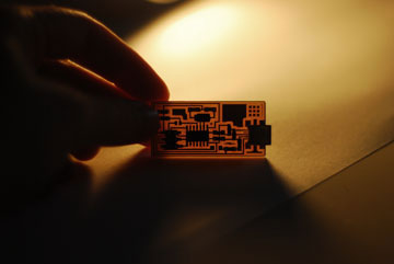
final boards; I also milled Andy Bardagjy's board which eliminates the USB component by integrating it into the board design.
4 programming
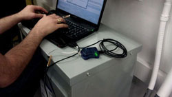
Costanza helped program the boards using an AVR programmer. After soldering, we connected the USB to the AVR programmer – make sure the 6 pin cable is oriented correctly (pin 1 to pin 1). Initially, the board kept getting a red light – so we checked the connections, added solder to some. I realized I had not closed SJ1 – the solder jumper near the microcontroller! After closing it (creating a solder bridge to connect the two ends), green light. The board is programmed using the (sudo) make fuse, (sudo) make program commands. Such a relief when no errors appear. Desolder SJ1, remove the 0 capacitor at SJ2, and the board is ready!