Making Almost Anything <-> MAS.863 <-> Fall 2011
Kristopher Dos Santos <-> Personal Robots Group
Week 6 <-> Mini Pumpkins

In this Halloween edition of How to Make, I scrapped the idea of trying to cast a hard rubber tire for something very simple and fun: a miniature jack-o-lantern! I had a creative idea for how exactly I wanted this to appear, but after struggling a bit with PartWorks 3D, and realizing the "joys" of undercuts and multi-part molds, I went with a very simple approach: model my positive mold to be a solid pumpkin in SolidWorks, use the fab modules to cut it on the Modela, and try to create a DryStone and a plastic cast of my little pumpkin. That's it! So, it was off to work!
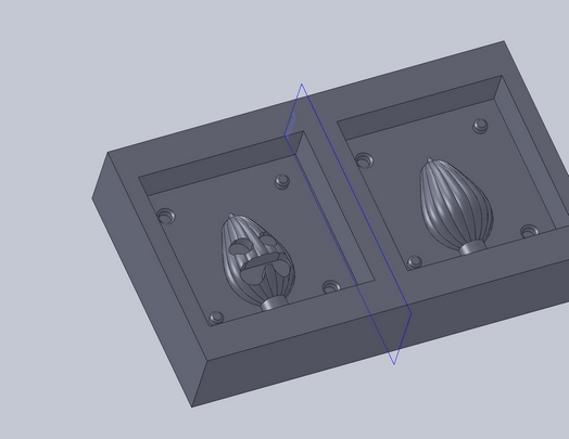
I designed this mold based on the single block of wax we received for creating our positive. I modeled it such that I could create this using a 1/8" flat end mill (hence the simple face on the pumpkin that reflects my future agony with the fab modules). Once this was designed, I exported this as a .stl file and moved into the zone of the dreaded fab modules.
Okay, since there aren't ANY good tutorials on how to do this, I will write one. This is how I've done it:
KDS's Guide to Creating a Positive Mold on the Modela Using Fab Modules and a STL from SolidWorks
- MAKE SURE YOU ACTUALLY DESIGN A POSITIVE MOLD! For example, are your registration keys in there? Can the bit that you're using cut around them? Do you have your pour spout and sprues designed?
- Export your model as an STL file and make sure that the extension is ".stl" and not ".STL", otherwise, the fab modules will not recognize them.
- Now, open up the fab modules (easiest to do this on the Modela workstation, since it's a shortcut on the Desktop), and use the "make_stl_rml" module. This workflow will do quite nicely.
- Now, here's' the breakdown: I'll separate this into each piece of the module; first is make_png
- To do this, you'll want to use the defaults that match with your design (if you designed in inches, select "inches" and so on).
- The axis that it will pick as the top face depends entirely on how you designed your part in SolidWorks (default is positive z). You want to select the axis that reflects what surface is being cut. For example, my mold was drawn on the x-y plane, and extruded in positive z, so positive z was my cutting surface.
- Hit make .png, and it if worked, you will see the .png appear on the module. Remember, light is near, and dark is far.
- Okay, next step is the .path part. This one is tricky.
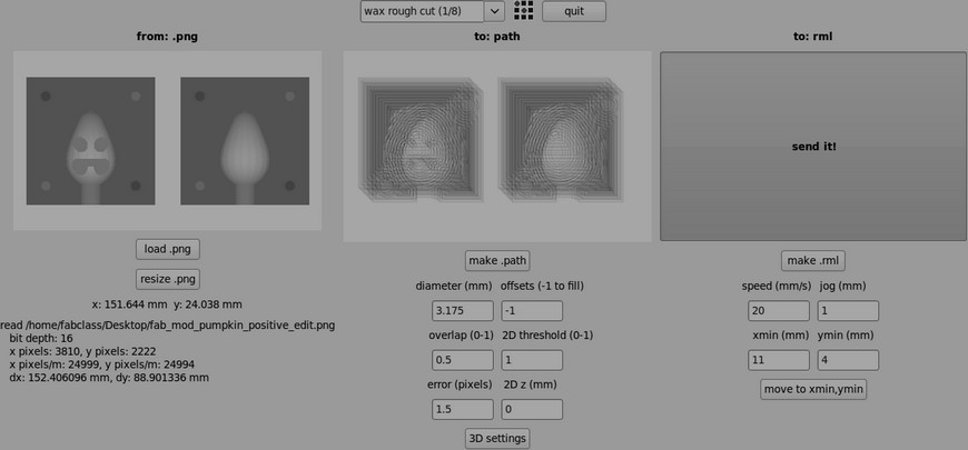
- Now, if you use make_png_rml, the default "wax 1/8 rough cut" will have everything you need, but I'll walk through the fields.
- Diameter (mm): This would be the diameter of your tool, in millimeters. 1/8" comes out to 3.175mm
- Offsets(-1 to fill): I can't stress this enough, but since right about now, you're doing a rough cut, ENTER -1!! Not doing this will cause a path file that does not cut out the layers, but rather, the outlines (translation: good way to break your bit).
- Overlap(0-1): This describes how much your tool will overlap its own cutting path. For a rough cut, using anywhere from 0.7 to 0.5 will do.
- 2D Threshold(0-1): Not really sure what this one does, but keep it at 1 (the defaults will usually do that for you).
- Error(pixels): 1.1 or 1.5, doesn't matter which.
- 2D Z (mm): Don't worry about this, because the 3D settings will override this. Now, hit 3D settings:
- You'll see another panel come up. Basically, don't touch any of the intensity fields; they're all set (top should be one, bottom should be zero).
- If you see on the right, there are Z settings; there are what you want to edit. Z top should be zero. Z bottom should be the deepest part OF YOUR CUT, NOT THE STOCK! Also, this should be a NEGATIVE value. The Z step size will determine how many slices will be taken of your model; 1-2mm should be okay for simple stuff, but do 0.3-0.7mm for complex molds. (For mine, I did 0.5mm.)
- WARNING: THE STEP SIZE WILL AFFECT HOW LONG YOUR ROUGH CUT WILL TAKE. THE LOWER IT IS IT, THE LONGER IT WILL TAKE!!! So bring something to do; it took 2.5 hours for my rough cut to finish.
- Hit close. Now you should be all set; hit make .path, and you should see a .png with your pretty path cutting layer by layer.
- Last part is the .rml part. This one isn't too bad.
- Before you do anything, set up your stock. If you are indeed working with wax, clean off the bed of the Modela, then align it with a region of the grid. Using the hot glue, fasten the block by hot gluing THE EDGES of your block, NOT THE BOTTOM! You will not be able to remove it if you do the latter. Gluing two edges will fasten it enough, but make sure it's a consistent stream of glue.
- Set up your bit using my previous instructions for the Modela. There's a convenient button on the module that will allow you to enter in x and y coordinates for the bit; use that to zero in on your block. Make sure you are indeed zeroing in on the right corner of you block.
- Once it is zeroed, make sure that the speed is 20mm/s and that the jog is 1mm. Once that is done, hit make .rml, then send it!
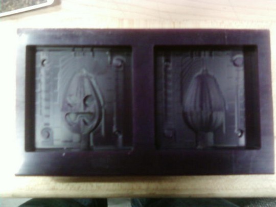
Once you have done that, you should get something like this:
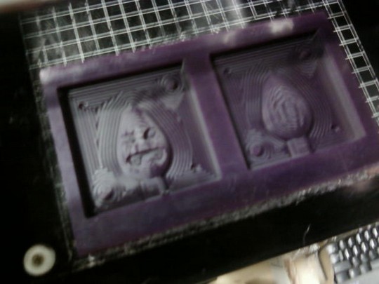
Now, time for the finish cut, WHICH IS EQUALLY IMPORTANT! DON'T SKIP IT!
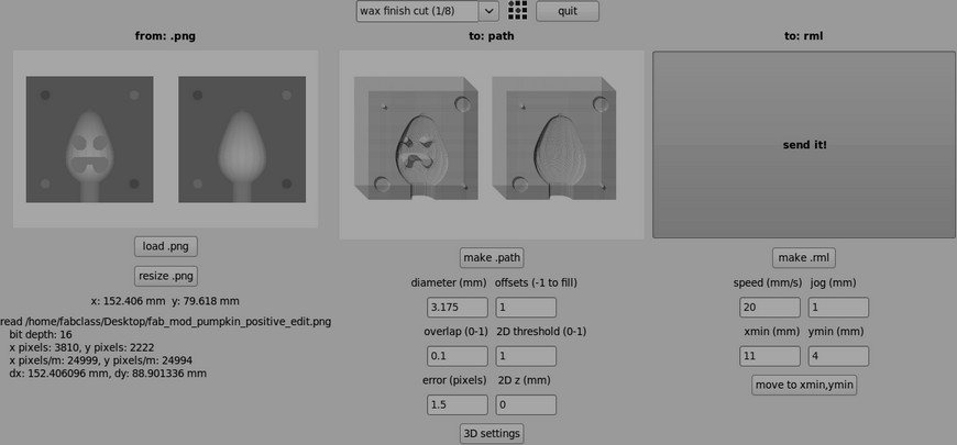
Setting this up is very similar to the rough cut, but with a few changes (primarily in the .path file):
- Offsets can now be changed to 1, since material has been cleared out of the way
- Your overlap should now be reduced to 0.1; this ensure a clean finish
- In the 3D settings, intensity should not change, and the Z settings should not change, but there are three little check boxes in the left corner that do need to be changed. Before, we used xy path. Now, we want to uncheck that, and check yz finish and (if you really want to be thorough) xz finish. You may only need to do just one (like me).
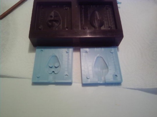
Once that is done, send the new .rml to the Modela. Your final thing should look similar.
Yay! Much cleaner. Notice how the curves of the pumpkin now show up in the mold, as well as the chamfers on the keys. Woohoo!
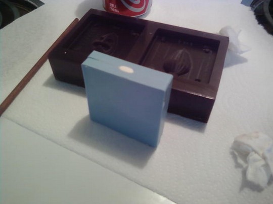
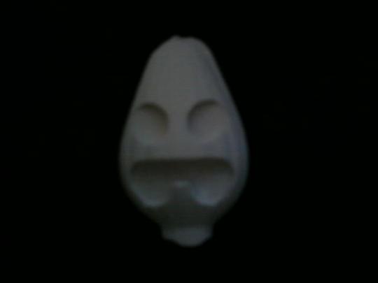
Here's the final pumpkin, cast in DryStone. Lessons learned:
- Silicone rubber molds aren't really designed to be two part molds; use it for one part fill molds
- The molding and casting process is messy; be carefull when handling these materials
- Some things turn out to be a lot thinner than expected
- Always do things for a bit longer than expected (mixing, casting, etc.)
Happy Halloween!
Back to home