This week I learned to use the waterjet and the ShopBot CNC.
Waterjet Autobot
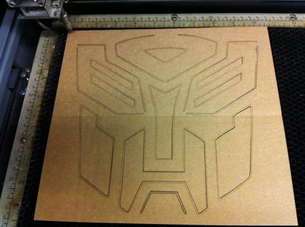
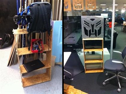
I used inkscape to trace a JPEG of the Transformers logo. This was done by selecting Path | Trace Bitmap and playing around with the Edge Detection settings (I later found out PartWorks’s produced better results). I then exported the vector graphics as DXF so I could open it in AutoCAD. I made a few test cuts on the laser cutter, removing some extra lines and adding connectors to hold the exterior better. When done, I converted all measurements to inches and saved the result as an R12 DXF, the only format OMAX Layout was willing to accept.
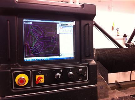
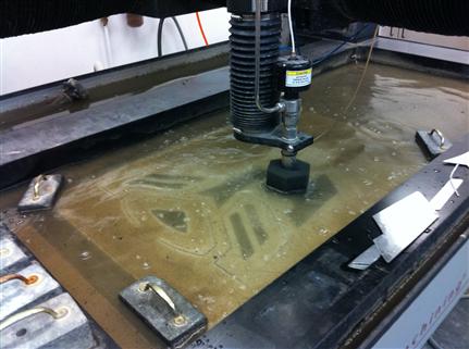
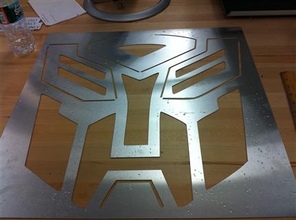
In OMAX Layout I scaled and rotated the logo, setting the cut quality to 3 for all lines. I then ran clean quite a few times (dozens? hundreds?) until overlaps/duplicates/gaps were 0. I added the leads but still couldn’t generate the whole path, so I cleaned the drawing several more times after adding the leads, until everything was 0 again. For cutting, I used a tool offset of 0.15 and a thickness of 1/32" (=0.03125"). Since some of my cuts required an inside kerf and some an outside one, I wanted to choose the kerf side manually. Unfortunately, the software used such a high zoom during side selection that it was impossible to make informed decisions. I decided to stick with the default (left). The actual cutting went pretty smooth, though some edges came out a little rough because the cut was on the “wrong” side. I also had to manually remove a couple of parts that were hanging on a thread after the job was done, probably the result of gaps in my drawing, which were too small to be connected by the gap connector process. A tiny hole between the logo’s “eyes” stands as a testament to a barely noticeable line I didn’t remove from drawing in time.
ShopBot Bookshelf
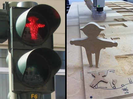
On my TA-monitored session I prepared an anatomically correct Red Ampelmann. Photo vs. the photo from berlin. I then experimented with pocketing, and learned that an OSB pocket is not deep enough to support the shelves in the bookshelf I had wanted to make.
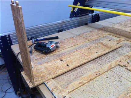
I drew the shelf parts in SolidWorks then saved as DXF, adding some last-minute fillets using AutoCAD. After opening the DXF in PartWorks, I saved it as CRV then re-opened, to change the measurements to inches. I then created two profile toolpaths: inside for holes and outside for the plates. Setting used (for OSB): short 0.125” spindle, 18000rpm, feed 80 in/min and plunge 60/min. I had to pause the cutting several times to drill additional screws into the board: OSB is very light and moves quite a lot. All in all, the job took about 15 minutes to complete.
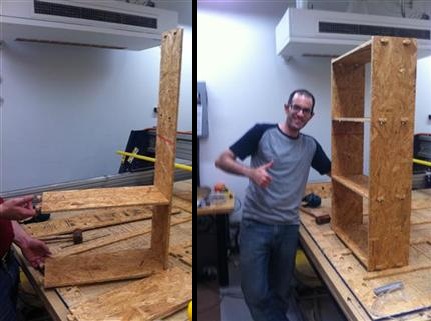
Unfortunately, it turned out the plates were too thick to fit in the slots prepared. Ozz and I tried sawing the slots a bit but that wasn’t enough. As I was struggling to make the necessary changes in SolidWorks, Ozz suggested I use the original drawing again, but calculate the toolpath as if I was using a 0.1” bit instead of 0.125”, thus making slightly wider cuts. This worked very nicely. A smaller value would have even been better and could spare me a few hammer blows.
