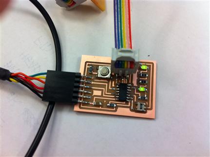
Change the sample board, make it, program it

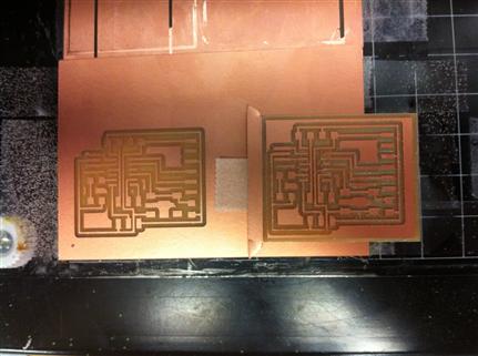
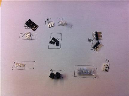
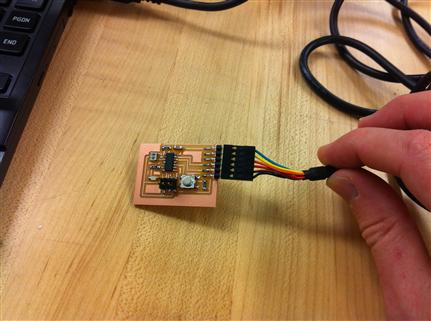
I added an LED and a button to the basic board, milled but and stuffed it, then connected it to my PC; the board was recognized by the driver bundled with AVR Studio. I used the Arduino sample David had showed us (replacing pin 13 with pin 7) to test the board; got an error message (intilization failed, rc =-1 Doublecheck connections and try again, or use -F to override this check.) and solved it by flipping the rainbow cable. Programming was successful but the LED still didn’t blink. Eyal showed me how to test communication using PuTTY, and we found out it didn’t communicate. I headed back to the shop and realized I soldered the LED the wrong way: the green stripe should be away from the power source and closer to the GND. As usual, upon removing the LED it came off with the traces.

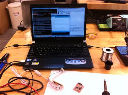
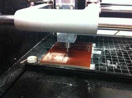
Back to square one. Mill, stuff, test, program with Arduino. This time, the LED blinked first! I then wrote a few simple programs, in C (blink LED on button press, blink LED a number of times as typed by the user) and Arduino (Blink LED, light LED on button press, serial communication).
  • 00
  • 01
  • 02
  • 03
  • 04
  • 05
  • 06

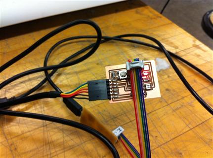
Time for some applied physics! I wanted to connect multiple LEDs so I designed a suitable board. Turns out that 5V (USB voltage) can power only two (green) LEDs connected in a series: voltage drop is ~2.1V per LED, and since its adds over a serial connection, 3 LEDs will require more voltage than the USB can provide. For my final project, I’ll need to increase the voltage, and also use parallel series of LEDs, each series with its own resistor. In the mean time I'm using 0 ohm resistors instead of the missing LEDs.

Even with just two LEDs the light wasn’t so bright, at least not with the 499 ohm resistor I originally used: two serial green LEDs incur a 4.2V voltage drop, leaving 0.8V to drop over the resistor; and according to Ohm’s law (R = I/V): 0.8 / 499 = ~1.6mA. This is sufficient for turning the LEDs on, but doesn’t produce a very bright light. Thanks Brian for helping me figure this out!


Connect to the board using PuTTY

Note that this would only work if the board was programmed for serial communication. If not (e.g., our basic LED blinking program) you will not be able to establish a connection

  1. Download PuTTY and install it.
  2. Launch PuTTY and use the following connection settings.
  3. Serial Line: use the COM value that matches the USB port to which you connected the board, e.g., COM4. In Windows you can check it through the Device Manager (Windows key + Break, then Device Manager.
  4. Speed: use the baud rate to which you programmed the board (maximum is 115200).
  5. Connection type: Serial.
  6. Save settings for future use, then click Open to communicate.
  7. If all works well, you should see characters typed to the terminal screen.