HOW TO MAKE (ALMOST) ANYTHING
TIFFANY TSENG - FALL 2011
| FABDUINO \\ HOW TO MAKE ONE (AND HOW NOT TO MAKE ONE) | ||||||||||||||||||||
INTRODUCTION The details on how to put together a Fabduino board are outlined on Ed Baafi's HTM page from 2010. This guide will walk through some of the troubleshooting steps you will most likely go through in the process of making a Fabduino board.
MILLING THE BOARD The workflow for cutting out your board is as follows:
Some things to watch out for when milling:
It takes about 25 minutes to cut out a board completely from the Modela, so budget your time accordingly! If you need to cancel a job, follow the instructions on this page under "How do I delete my job." You will need to enter the following commands into the terminal: ps -aux | grep catkill xxxx Also, be careful of sanding your board in the shop. I used the circular bandsaw and cut my board in half!
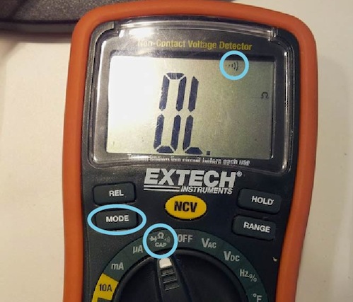
STUFFING THE BOARD Before stuffing you board, I recommend checking your traces with a multimeter.This involves using the continuity check mode on the multimeter, which is usually indicated by an audio symbol:
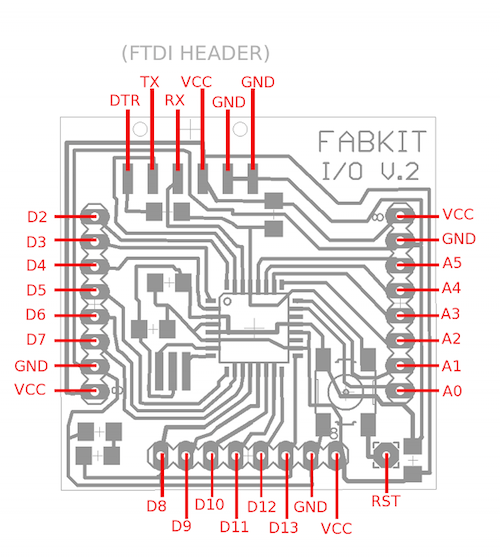
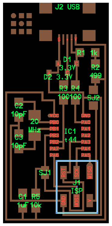
Go around your Fabduino board and check that none of the pins on the perimeter of the board are connected to one another (meaning the pins labeled in the diagram below). If they are, take an xacto blade and run along the edges of the traces to remove any extra copper.
After you're done checking, go ahead and solder your components onto the board. Here are a list of parts you will need for your board:
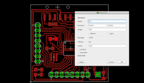
You can check where the components go by referring to the Eagle files (board + schematic). As a reminder, if you open up the brd file, you can type "info" and then click on any component in the layout, and it will open up a properties file with the component name and value.
Using the flux pen Do it! Use a flux pen to add flux around all the itty-bitty microcontroller pads on the board. Then apply solder, and it will flow nicely without clumping up. If it does, just use solder wick to remove the extra solder. DEBUGGING There are a few things you should do to test your board before even trying to program it.
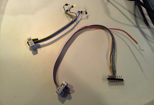
PROGRAMMING THE BOARD To program the board, you need to make a connector that connects the programmer header pins on the FABISP to those on your Fabduino. There are many ways to do this. I used two different ways (for different boards I made):
You can solder male headers to the end of the ribbon wire and connect those to the female headers on your board. Or you can solder them directly to a row of male headers, making sure that the order matches that of the Fabduino board. You need to check that the MISO, MOSI, etc line up on both boards:
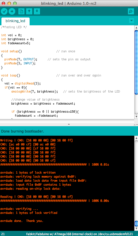
The steps for programming your board are nicely outlined on Ed's site, so I won't repeat them here. If you get an error in Arduino about checking your connections, go back to the debugging section of this page to run through the steps of checking your board. When you're done, you should get a message that looks like this:
Congratulations, you have a Fabduino!! |
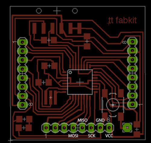
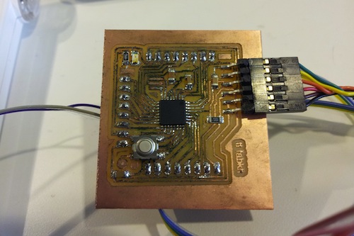 A finished Fabduino
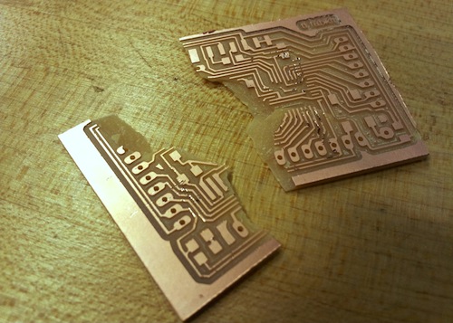