Week 9 -- Input
11/05/12
Introduction
This week we're focusing on input devices. I decided to make a frequency detector with the photodiode circuit that Neil put up as a demo. The photodiode would receive incident modulated light (modulated somewhere between 100Hz and a few kHz) and would be able to determine either the frequency (to some accuracy) or whether or not the incident frequency was within a certain range.
Board Design and Build
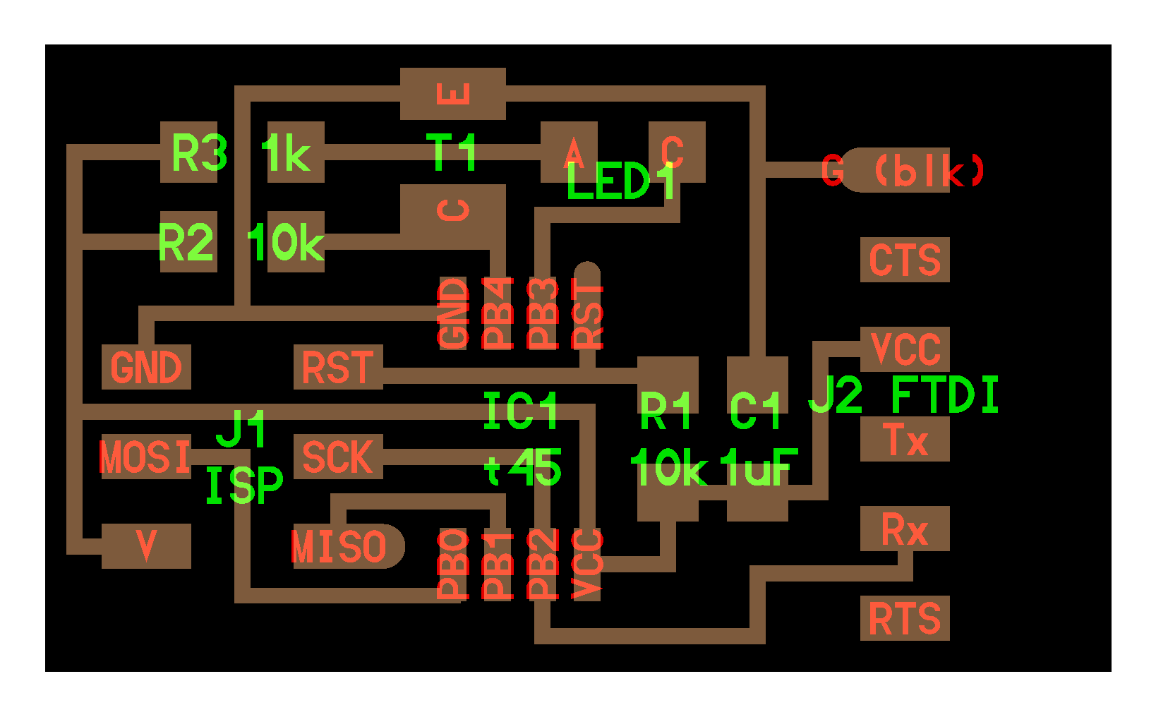
I used the board that Neil used in his synchronous detection demo example. Milling went as planned, but while stuffing the board, I noticed that the phototransistors available in the electronics room were different than the one in the picture of Neil's original board. I wound up using that transistor, but putting it on backwards (since I had to guess which side was the cathode of the original part - we had no schematic to work from). This became evident after programming the board and running the python interface. The phototransistor reacted very little to variations in light. I flipped the component and all was working smoothly from then on.
Frequency Detection
I began testing the circuit as is to observe if the 'diff' value varies in it's behavior as a function of the frequency of the incident light. I figured that given the filtering window we were using, there should be some resonant frequencies that produce much larger swings in the read-out value. I connected an LED to a function generator and shined the LED towards the phototransistor. I varied the frequency of the LED and did indeed observe variation in the behavior of the ouput as a function of frequency (see the video below).

