| [15++] ~ FINAL PROJECT |
|
For my final project I'm working on a handheld CNC machine... 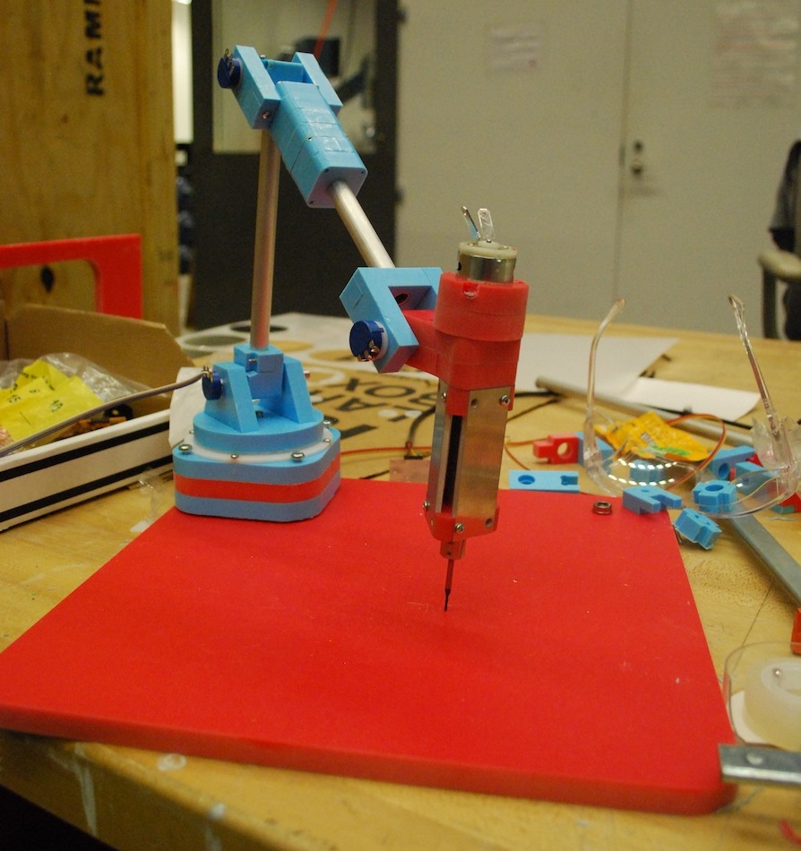
what will it do? It will be a hand-held CNC milling tool. The user will be carve precise objects from computer designs.who's done what beforehand? Amit Zoran has created something very similar called the FreeD and he is pursuing it as his PhD work. Unlike him, I’ll be using a coordinate measuring arm instead of the magnetic position tracking he used. This should ideally result in objects with finer details and smoother finishes.What materials and components will be required? Arm I will need some strong, stiff materials to make the arm out of. I’m currently planning on using aluminum rails with an internal HDPE core. Position Estimation I need angular sensors at each joint to be able to use forward kinematics to know the position of the tool in space. Spindle I need a spindle to be able to mill machinable wax. The spindle should also be able to retract such that it can be raised so as not to damage the 3D model.where will they come from? I will order the majority of the parts from places like Mcmaster and SDP-SI. I plan to make the angular position sensors myself using capacitive sensors. As a fallback plan I will order some high precision potentiometers.how much will it cost? The parts cost will be on the order of $50’s.what parts and systems will be made? Arm, Position Estimation & Control Algorithm, and Spindlewhat processes will be used? shopbot milling, waterjetting, lasercutting, PCB milling, Solderingwhat tasks need to be completed? I need to fabricate the arm, design the control system,what questions need to be answered? I’m still unsure as to whether the CVDT will give me high enough position measurement resolution. The joints and arm-members need to be very stiff. I’m not sure if aluminum and HDPE will suffice. I’m also unsure of what the best way to make the joints will be.what is the schedule? Wednesday: Design arm + order remaining parts Thursday: Arm fabrication Friday: Design + Mill circuit boards Saturday: control design + system integration Sunday: testing part 1 Monday: testing part 2how will it be evaluated? The evaluation will be primarily qualitative. I expect to be able to use the tool to make reasonably good looking objects. I may start with simple shapes like a cube to aid in evaluating its accuracy and precision.This week I modified my spindle and added a hall-effect sensor to do closed loop speed control. I also validated my RPM measurement with a optical tachometer. Here's a video of the speed measurement: 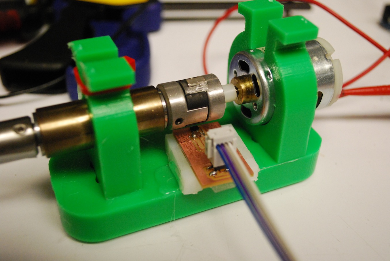
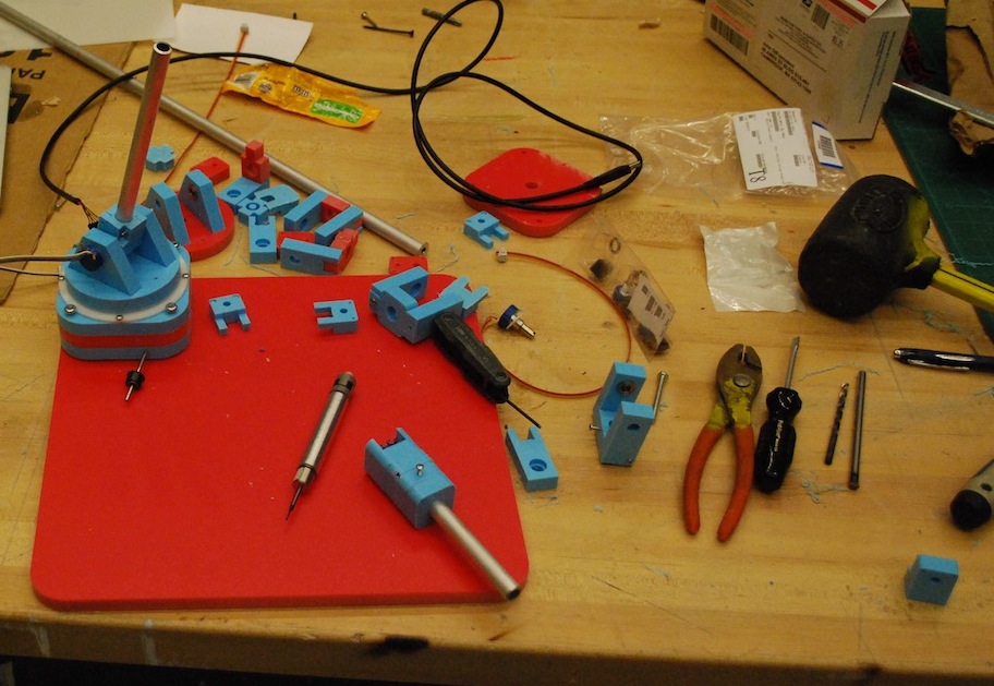
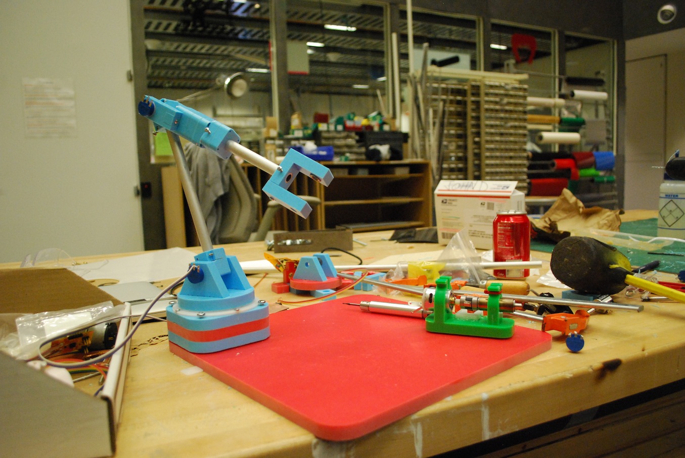
Update (i.e., how did it all come together?): It was an insane two weeks but I'm really happy with the final result. I designed the arm in Solidworks. I paid special attention to the design of the joints. I wanted to ensure everything was structurally stable so it would have reliable positioning accuracy and not break every week. Having taken Precision Machine Design this semester as well, I applied all the tips and tricks to ensure optimal stiffness in my arm and joints. Most joints are supported on each side by a ball bearing. Since the base joint and wrist-rotation joint couldn't be supported in double-shear, I made sure to space the support bearings by 3 to 5 times the characteristic length of the shaft (in this case the 1/4" diameter). I originally wanted to waterjet as much of the pieces that I could because it's so much faster and lets me get smaller feature sizes. Unfortunately some of my parts were a little small and didn't come out so well. So... I redesigned everything to be milled on the shopbot out of my favorite colorful HDPE cutting board material. I wanted to use a drilling toolpath to make 4-40 interference holes in many of the parts but couldn't figure out how to use the drill chuck in the shopbot. Instead, I used a 1/16" super-O 1 flute upcut endmill (thanks Sam!) to start the holes and then had to drill through each one because the endmill didn't have the necessary cutting length to get through the 0.5" material. Annoying but not terrible... 
On to assembling! This was a bit of a time consuming process. In retrospect I think I would've liked to spend a little more upfront time desiging pieces that pressfit and snapfit rather than using all the hardware I did. The reason I used hardware was to try to get the design in as small a package as possible and so that it required as little machining time as possible. Ultimately though I spent a ton of time drilling out holes to proper sizes and needed to do awkward clamping + drilling jobs to ensure everything lined up squarely. 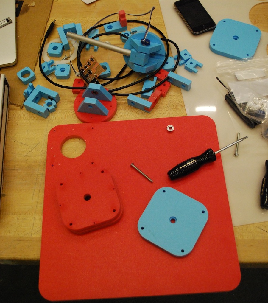 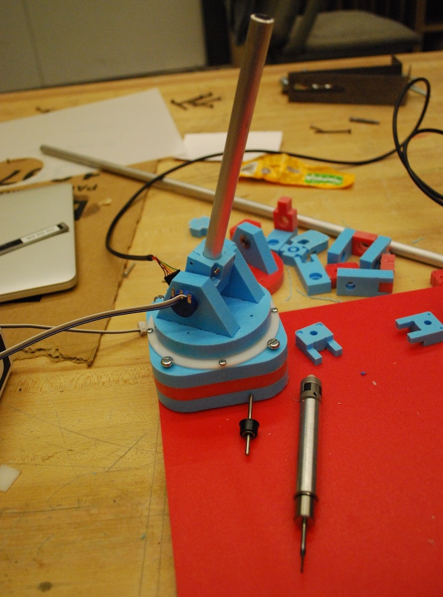

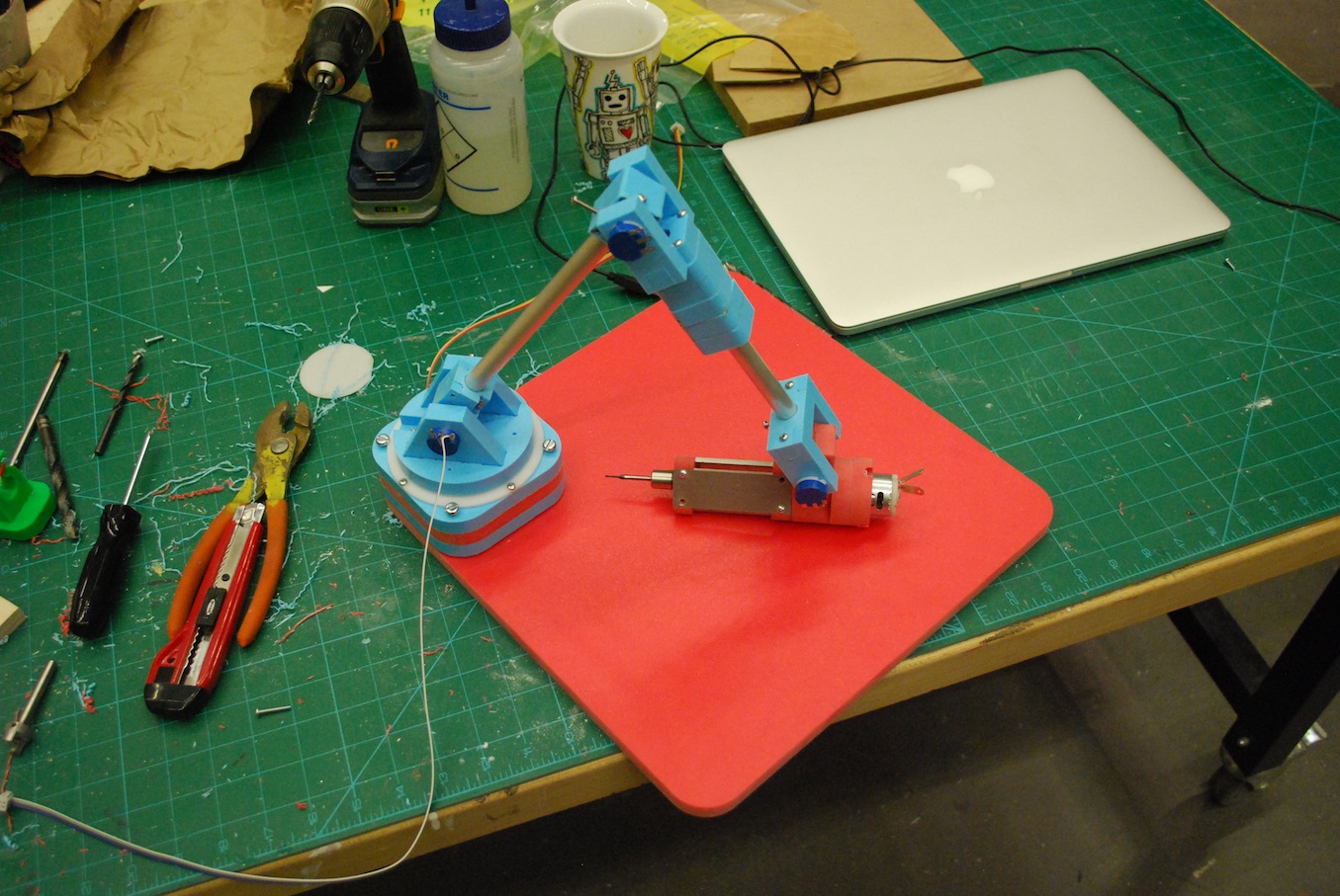
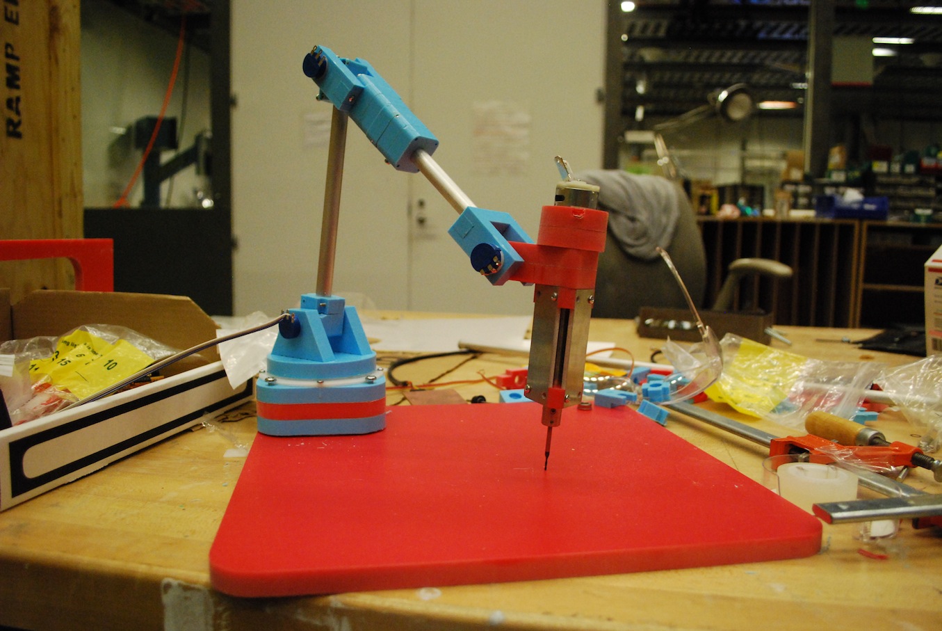
I'm using high-precision (very linear and temperature independent) potentiometers to measure joint angles. This isn't ideal given the 10-bit ADC of the Attiny44 but I think I'm still capable of getting on the order of 0.5mm accuracy across the entire workenvelope. Upgrading the ADC to one with 12 bits would bring that down to the 100 micron realm. I made an upgraded analog breakout board to get the sensor data into the computer. 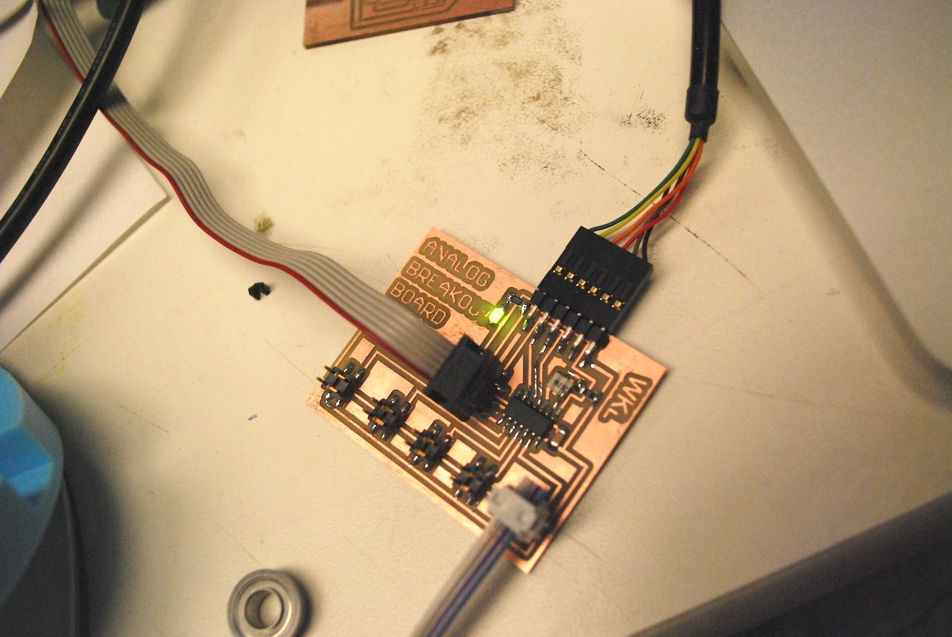
The data is still being sent in through firefly/grasshopper and then visualized in Rhino. The spindle speed is controlled using the separate mosfet motor controller board I made in output week. Next Steps So currently I can get the joint angles into Rhino and calculate the distance from the tool to the mesh surface. I can also control the speed of the spindle. The next step is integrating the two such that the spindle speed slows down as the tool approaches the surface of the mesh. Source:
|